Trix El 12 User manual

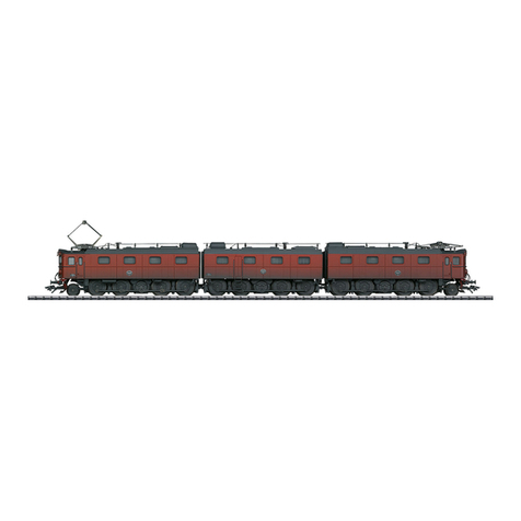
Modell der schweren Erzlok Reihe El 12
22277
D
GB
F
USA
NL

2
Inhaltsverzeichnis: Seite
Informationen zum Vorbild 4
Sicherheitshinweise 6
Wichtige Hinweise 6
Multiprotokollbetrieb 6
Hinweise zum Digitalbetrieb 7
Schaltbare Funktionen 9
Parameter/Register 10
Betriebshinweise 26
Wartung und Instandhaltung 27
Ersatzteile 32
Table of Contents: Page
Information about the prototype 4
Safety Notes 11
Important Notes 11
Multi-Protocol Operation 11
Notes on digital operation 12
Controllable Functions 14
Parameter/Register 15
Information about operation 26
Service and maintenance 27
Spare Parts 32

3
Sommaire : Page
Informations concernant la locomotive réelle 5
Remarques importantes sur la sécurité 16
Information importante 16
Mode multiprotocole 16
Remarques relatives au fonctionnement
en mode digital 17
Fonctions commutables 19
Paramètre/Registre 20
Remarques sur l’exploitation 26
Entretien et maintien 27
Pièces de rechange 32
Inhoudsopgave: Pagina
Informatie van het voorbeeld 5
Veiligheidsvoorschriften 21
Belangrijke aanwijzing 21
Multiprotocolbedrijf 21
Aanwijzingen voor digitale besturing 22
Schakelbare functies 24
Parameter/Register 25
Opmerkingen over de werking 26
Onderhoud en handhaving 27
Onderdelen 32

4
Information about the Prototype
In February of 1952, the Swedish State Railways decided to
order six double electric locomotives of the new class Dm,
based on the class Da being built at that time. These six
units were for hauling heavy ore trains from Gällivare and
Kiruna. Like the Da the Dm was also equipped with side rod
drive that had been technically obsolete for a long time by
then. Each locomotive part was powered by two single-
phase series-wound motors that were geared to a jackshaft
between the four sets of driving wheels. The driving wheels
were connected by means of side rods to the jackshaft. A
single-axle pilot truck at the end with the engineer’s cab for
better tracking completed the locomotive. Due to the small
quantity to be purchased, the Norwegian State Railways
(NSB) also had to drink from the bitter cup of side rod drive
and link up a few weeks later with the SJ’s Dm order with
three additional double electric locomotives. These units
were designated on the NSB as the class El 12 and were
delivered in the spring of 1954 with the road numbers 2113-
2118. A fourth double electric locomotive followed in June
of 1957 with road number El 12 2119/2120. Between 1965 and
1968, the NSB had their El 12 units rebuilt in such a way that
the eight single units were assembled out of road number
sequence into triple traction locomotives. They were
equipped with sturdy buffer beams on the close-coupled
ends for this purpose. From 1968 on the NSB had two triple
unit El 12 locomotives as well as two reserve parts available
for use. After 1984, the El 12 units became superfluous and
were maintained only as reserve locomotives. They were re-
tired between 1987 and 1992. Road numbers El 12 2113/2115
and 2119/2120 remain preserved as museum locomotives.
Information zum Vorbild
Zur Beförderung der schweren Erzzüge aus Gällivare und
Kiruna entschlossen sich die Schwedischen Staatsbahnen
(SJ) im Februar 1952 zur Bestellung von sechs Doppelloks
der neuen Baureihe Dm, welche auf der gerade in Bau
befindlichen Baureihe Da basierte. Wie die Da erhielten
auch die Dm einen zu jener Zeit technisch schon lange
überholten Stangenantrieb. Jedes Lokteil wurde von zwei
Einphasen-Reihenschlussmotoren angetrieben, welche über
ein Getriebe auf die Blindwelle zwischen den vier Treibrad-
sätzen wirkten. Diese waren über Kuppelstangen mit der
angetriebenen Blindwelle verbunden. Ein Laufradsatz zur
besseren Spurführung am Führerstandsende vervollstän-
digte das Ganze. Wegen der zu beschaffenden geringen
Stückzahl mussten die norwegischen Staatsbahnen (NSB)
in den sauren Apfel des Stangenantriebs beißen und sich
ein paar Wochen später mit drei weiteren Doppelloks an
die Dm-Bestellung der SJ anschließen. Die bei den NSB
als Baureihe El 12 bezeichneten Maschinen wurden im
Frühjahr 1954 mit den Nummern 2113-2118 ausgeliefert. Mit
der El 12 2119/2120 folgte im Juni 1957 eine vierte Doppellok.
Zwischen 1965 und 1968 ließen die NSB ihre El 12 dergestalt
umbauen, dass sich die acht Einzelteile in beliebiger
Reihenfolge zu Tresektionsloks zusammenstellen ließen.
Hierfür erhielten sie u.a. stabile Pufferbohlen an den Kurz-
kupplungsenden angebaut. Ab 1968 standen so den NSB
zwei dreiteilige El 12 sowie zwei Reserveteile zur Verfügung.
Nach 1984 wurden die El 12 überflüssig und nur noch als Re-
serveloks vorgehalten. Zwischen 1987 und 1992 erfolgte ihre
Ausmusterung. Die El 12 2113/2115 und 2119/2120 blieben als
Museumslok erhalten.

5
Informations concernant la locomotive réelle
Pour remorquer les lourds trains de minerais de Gällivare et
Kiruna, les chemins de fer suédois (SJ) décidèrent en février
1952 de commander six doubles locomotives de la nouvelle
série Dm, qui se basait sur la série Da à l’époque en construc-
tion. Tout comme la DA, la Dm fut équipée d’un système de
transmission par bielles alors déjà bien dépassé. Chaque
élément de la locomotive était entraîné par deux moteurs
monophasés à excitation série qui agissaient sur l’arbre
secondaire de renvoi entre les quatre essieux moteurs via un
engrenage. Ces quatre essieux moteurs étaient reliés à l’arbre
secondaire de renvoi via des bielles d’accouplement. Pour un
meilleur guidage latéral du boudin, un essieu porteur situé à
l’extrémité de la cabine de conduite venait compléter le tout. En
raison du petit nombre d’unités à acquérir, les chemins de fer
norvégiens (NSB) durent se résigner à l’utilisation du système
de transmission par bielles et se rallier quelques semaines
plus tard à la commande des SJ pour la série Dm avec trois
autres doubles locomotives. Les machines désignées par les
NSB comme série El 12 furent livrées au printemps 1954 sous
les numéros 2113 à 2118. En juin 1957, la El 12 2119/2120 repré-
sentait la quatrième double locomotive. Entre 1965 et 1968, les
NSB firent transformer leurs El 12 de manière à ce que les huit
éléments puissent être assemblés librement en locomotives
à trois éléments. A cet effet, les éléments furent munis entre
autres de solides traverses porte-tampons aux extrémités des
attelages courts. A partir de 1968, les NSB disposaient donc de
deux El 12 à trois éléments et de deux éléments de réserve. A
partir de 1984, les El 12 devinrent superflues et ne furent plus
gardées que comme locomotives de réserve. Leur réforme eut
lieu entre 1987 et 1992. La El 12 2113/2115 et la 2119/2120 furent
conservées comme locomotives musée.
Informatie van het voorbeeld
Voor het trekken van de zware ertstreinen uit Gällivare en
Kiruna besloten de Zweedse staatsspoorwegen (SJ) in fe-
bruari 1952 om zes dubbellocomotieven van de nieuwe serie
Dm te bestellen. Deze waren gebaseerd op de dat moment in
productie zijnde locs van de serie Da. Evenals de Da kregen
ook de Dm een, destijds technisch al lang achterhaalde, drijf-
stangenaandrijving. Elk locdeel werd door twee enkelfase
-seriemotoren aangedreven welke via een overbrenging
het blinde wiel tussen de vier drijfwielen aandreven. Deze
waren via koppelstangen verbonden met het aangedreven
blindwiel. Een loopwielas onder het eind van de cabine voor
een betere spoorvoering complementeerde het geheel. Van-
wege het te geringe aantal aan te schaffen locs moesten de
Noorse staatsspoorwegen (NSB) door de zure appel van de
drijfstangenaandrijving heen bijten om zich een paar weken
later met een bestelling van drie dubbellocs aan te sluiten
bij de bestelling van de SJ. De bij de NSB als serie El 12
gekenmerkte machines werden in het voorjaar van 1954 met
de nummers 2113-2118 uitgeleverd. Met de El 12 2119/2120
volgende in juni een vierde dubbelloc. Tussen 1965 en 1968
lieten de NSB hun El 12 dusdanig ombouwen dat er acht en-
kel locomotieven ontstonden die in willekeurige volgorde als
drievoudige tractie samengesteld konden worden. Hiervoor
kregen ze o.a. een stabiele bufferbalk aan de kortgekoppelde
zijde. Vanaf 1968 had de NSB op deze wijze de beschikking
over twee driedelige El 12 en twee reserve delen. Na 1984
werden de El 12 overbodig en alleen nog als reserve locs
aangehouden. Tussen 1987 en 1992 volgde dan ook de bui-
tendienststelling. De El 12 2113/2115 en de 2119/2120 beleven
als museumloc behouden.
6
Sicherheitshinweise
• Die Lok darf nur mit einem dafür bestimmten Betriebssys-
tem eingesetzt werden.
• Analog max. 15 Volt =, digital max. 22 Volt ~.
• Die Lok darf nur aus als einer Leistungsquelle versorgt
werden.
• Beachten Sie unbedingt die Sicherheitshinweise in der
Bedienungsanleitung zu Ihrem Betriebssystem.
• Für den konventionellen Betrieb der Lok muss das An-
schlussgleis entstört werden. Dazu ist das Entstörset
611 655 zu verwenden. Für Digitalbetrieb ist das Entstör-
set nicht geeignet.
• ACHTUNG! Funktionsbedingte scharfe Kanten und Spitzen.
• Setzen Sie das Modell keiner direkten Sonneneinstrah-
lung, starken Temperaturschwankungen oder hoher
Luftfeuchtigkeit aus.
Wichtige Hinweise
• Die Bedienungsanleitung und die Verpackung sind
Bestandteile des Produktes und müssen deshalb aufbe-
wahrt sowie bei Weitergabe des Produktes mitgegeben
werden.
• Für Reparaturen oder Ersatzteile wenden Sie sich bitte an
Ihren Trix-Fachhändler.
• Gewährleistung und Garantie gemäß der beiliegenden
Garantieurkunde.
• Entsorgung: www.maerklin.com/en/imprint.html
• Der volle Funktionsumfang ist nur unter Trix Systems,
DCC und unter mfx verfügbar.
• Eingebaute, fahrtrichtungsabhängige Stirnbeleuchtung.
Im Digitalbetrieb schaltbar.
• Befahrbarer Mindestradius 360 mm.
Multiprotokollbetrieb
Analogbetrieb
Der Decoder kann auch auf analogen Anlagen oder Gleis-
abschnitten betrieben werden. Der Decoder erkennt die
analoge Gleichspannung (DC) automatisch und passt sich
der analogen Gleisspannung an. Es sind alle Funktionen,
die unter mfx oder DCC für den Analogbetrieb eingestellt
wurden aktiv (siehe Digitalbetrieb).
Digitalbetrieb
Der Decoder ist ein Multiprotokolldecoder. Der Decoder
kann unter folgenden Digital-Protokollen eingesetzt werden:
mfx oder DCC.
Das Digital-Protokoll mit den meisten Möglichkeiten ist das
höchstwertige Digital-Protokoll. Die Reihenfolge der Digital-
Protokolle ist in der Wertung fallend:
Priorität 1: mfx
Priorität 2: DCC
Priorität 3: DC
Hinweis: Digital-Protokolle können sich gegenseitig beein-
flussen. Für einen störungsfreien Betrieb empfehlen wir,
nicht benötigte Digital-Protokolle mit CV 50 zu deaktivieren.
Deaktivieren Sie, sofern dies Ihre Zentrale unterstützt, auch
dort die nicht benötigten Digital-Protokolle.

7
Werden zwei oder mehrere Digital-Protokolle am Gleis
erkannt, übernimmt der Decoder automatisch das höchst-
wertige Digital-Protokoll, z.B. mfx/DCC, somit wird das
mfx-Digital-Protokoll vom Decoder übernommen.
Hinweis: Beachten Sie, dass nicht alle Funktionen in allen
Digital-Protokollen möglich sind. Unter mfx und DCC können
einige Einstellungen von Funktionen, welche im Analog-
Betrieb wirksam sein sollen, vorgenommen werden.
Hinweise zum Digitalbetrieb
• Die genaue Vorgehensweise zum Einstellen der diversen
Parameter entnehmen Sie bitte der Bedienungsanleitung
Ihrer Mehrzug-Zentrale.
• Die ab Werk eingestellten Werte sind für mfx gewählt, so
dass ein bestmöglichstes Fahrverhalten gewährleistet ist.
Für andere Betriebssysteme müssen gegebenenfalls
Anpassungen getätigt werden.
• Der Betrieb mit gegenpoliger Gleichspannung im
Bremsabschnitt ist mit der werkseitigen Einstellung
nicht möglich. Ist diese Eigenschaft gewünscht, so muss
auf den konventionellen Gleichstrombetrieb verzichtet
werden (CV 29/Bit 2 = 0).
mfx-Protokoll
Adressierung
• Keine Adresse erforderlich, jeder Decoder erhält eine
einmalige und eindeutige Kennung (UID).
• Der Decoder meldet sich an einer Central Station oder
Mobile Station mit seiner UID automatisch an.
Programmierung
• Die Eigenschaften können über die grafische Oberfläche
der Central Station bzw. teilweise auch mit der Mobile
Station programmiert werden.
• Es können alle Configurations Variablen (CV) mehrfach
gelesen und programmiert werden.
• Die Programmierung kann entweder auf dem Haupt- oder
dem Programmiergleis erfolgen.
• Die Defaulteinstellungen (Werkseinstellungen) können
wieder hergestellt werden.
• Funktionsmapping: Funktionen können mit Hilfe der
Central Station 60212 (eingeschränkt) und mit der Central
Station 60213/60214/60215 beliebigen Funktionstasten
zugeordnet werden (Siehe Hilfe in der Central Station).
DCC-Protokoll
Adressierung
• Kurze Adresse – Lange Adresse – Traktionsadresse
• Adressbereich:
1 - 127 kurze Adresse, Traktionsadresse
1 - 10239 lange Adresse
• Jede Adresse ist manuell programmierbar.
• Kurze oder lange Adresse wird über die CVs ausgewählt.
• Eine angewandte Traktionsadresse deaktiviert die
Standard-Adresse.
Programmierung
• Die Eigenschaften können über die Configurations Varia-
blen (CV) mehrfach geändert werden.
• Die CV-Nummer und die CV-Werte werden direkt einge-

8
geben.
• Die CVs können mehrfach gelesen und programmiert
werden (Programmierung auf dem Programmiergleis).
• Die CVs können beliebig programmiert werden (Program-
mierung auf dem Hauptgleis PoM). PoM ist nur bei den in
der CV-Tabelle gekennzeichneten CV möglich. Die Pro-
grammierung auf dem Hauptgleis (PoM) muss von Ihrer
Zentrale unterstützt werden (siehe Bedienungsanleitung
ihres Gerätes).
• Die Defaulteinstellungen (Werkseinstellungen) können
wieder hergestellt werden.
• 14 bzw. 28/126 Fahrstufen einstellbar.
• Alle Funktionen können entsprechend dem Funktions-
mapping geschaltet werden.
• Weitere Information, siehe CV-Tabelle DCC-Protokoll.
Es wird empfohlen, die Programmierungen grundsätzlich auf
dem Programmiergleis vorzunehmen.
Logische Funktionen
Anfahr-/Bremsverzögerung
• Die Beschleunigungs- und Bremszeit kann getrennt
voneinander eingestellt werden.
• Die logische Funktionsabschaltung ABV kann über das
Funktionsmapping auf jede beliebige Funktionstaste
gelegt werden.

9
Schaltbare Funktionen
Stirnbeleuchtung an Funktion f0 Funktion f0
drittes Spitzenlicht — Funktion 1 Funktion f1 Funktion f1
Betriebsgeräusch — Funktion 2 Funktion f2 Funktion f2
Geräusch: Horn — Funktion 3 Funktion f3 Funktion f3
ABV, aus — Funktion 4 Funktion f4 Funktion f4
Maschinenraumbeleuchtung — Funktion 5 Funktion f5 Funktion f5
Führerstandsbeleuchtung 1 — Funktion 6 Funktion f6 Funktion f6
Geräusch: Rangierhorn — Funktion 7 Funktion f7 Funktion f7
Führerstandsbeleuchtung 2 — Funktion 8 Funktion f8 Funktion f8
Geräusch: Bremsenquietschen aus — — Funktion f9 Funktion f9
Geräusch: Ankuppeln (Puffer an Puffer) — — Funktion f10 Funktion f10
Geräusch: Lüfterantrieb — — Funktion f11 Funktion f11
Geräusch: Pressluft — — Funktion f12 Funktion f12
Geräusch: Pantograph — — Funktion f13 Funktion f13
STOP mobile station
15
f0 f8 f0f8
f0 - f3 f4 - f7

10
CV Bedeutung Wert DCC ab Werk
1 Adresse 1 - 127 3
2 PoM Minimalgeschwindigkeit 0 - 255 18
3 PoM Anfahrverzögerung 0 - 255 15
4 PoM Bremsverzögerung 0 - 255 15
5 PoM Maximalgeschwindigkeit 0 - 255 230
8 Werkreset/Herstellerkennung 8 131
13 PoM Funktionen F1 - F8 im Analogbetrieb 0 - 255 0
14 PoM Funktionen F9 - F15 und Licht im Analogbetrieb 0 - 255 1
17 Erweiterte Adresse (oberer Teil) CV 29, Bit 5 =1 192
18 Erweiterte Adresse (unterer Teil) CV 29, Bit 5 =1 128
19 Traktionsadresse 0 - 255 0
21 PoM Funktionen F1 - F8 bei Traktion 0 - 255 0
22 PoM Funktionen F9 - F15 und Licht bei Traktion 0 - 255 0
29 PoM
Bit 0: Umpolung Fahrtrichtung
Bit 1: Anzahl Fahrstufen 14 oder 28/128*
Bit 2: DCC Betrieb mit Bremsstrecke (kein Analogbetrieb möglich)
Bit 5: Adressumfang 7 Bit / 14 Bit
0 / 1
0 / 2
0 / 4
0 / 32
***
0, 1, 2, 3, 4, 5, 6,
7, 32, 34, 35, 36,
37, 38, 39
6
63 PoM Lautstärke 0 - 255 255
PoM Program on the Main; muss vom Steuergerät unterstützt werden
* Fahrstufen am Lokdecoder und am Steuergerät müssen übereinstimmen, es sind sonst Fehlfunktionen möglich
*** die Werte der gewünschten Einstellungen sind zu addieren

11
• Built-in headlights that change over with the direction of
travel. They can be turned on and off in digital operation.
• Minimum radius for operation is 360 mm/14-3/16“.
Multi-Protocol Operation
Analog Operation
This decoder can also be operated on analog layouts or ar-
eas of track that are analog. The decoder recognizes alter-
nating current (DC) and automatically adapts to the analog
track voltage. All functions that were set under mfx or DCC
for analog operation are active (see Digital Operation).
Digital Operation
The decoders are multi-protocol decoders. These decoders
can be used under the following digital protocols: mfx or DCC.
The digital protocol with the most possibilities is the highest
order digital protocol. The sequence of digital protocols in
descending order is:
Priority 1: mfx
Priority 2: DCC
Priority 3: DC
Note: Digital protocols can influence each other. For trouble-
free operation, we recommend deactivating those digital
protocols not needed by using CV 50. Deactivate unneeded
digital protocols at this CV if your controller supports this
function.
If two or more digital protocols are recognized in the track,
the decoder automatically takes on the highest order digital
protocol, example: mfx/DCC; the decoder takes on the mfx
digital protocol.
Safety Notes
• This locomotive is only to be used with the operating
system it is designed for.
• Analog max. 15 volts DC, digital max. 22 volts AC.
• This locomotive must never be supplied with power from
more than one power pack.
• Please make note of the safety notes in the instructions
for your operating system.
• The feeder track must be equipped to prevent inter-
ference with radio and television reception, when the
locomotive is to be run in conventional operation. The
611 655 interference suppression set is to be used for this
purpose. The interference suppression set is not suitable
for digital operation.
• WARNING! Sharp edges and points required for operation.
• Do not expose the model to direct sunlight, extreme
changes in temperature, or high humidity.
Important Notes
• The operating instructions and the packaging are a com-
ponent part of the product and must therefore be kept as
well as transferred along with the product to others.
• Please see your authorized Trix dealer for repairs or
spare parts.
• The warranty card included with this product specifies
the warranty conditions.
• Disposing: www.maerklin.com/en/imprint.html
• The full range of functions is only available under Trix
Systems and under DCC.

12
Note: Please note that not all functions are possible in all
digital protocols. Several settings for functions, which are
supposed to be active in analog operation, can be done
under mfx and DCC.
Notes on digital operation
• The operating instructions for your central unit will give
you exact procedures for setting the different parame-
ters.
• The values set at the factory have been selected for mfx
in order to guarantee the best possible running characte-
ristics.
Adjustments may have to be made for other operating
systems.
• The setting done at the factory does not permit operation
with opposite polarity DC power in the braking block.
If you want this characteristic, you must do without
conventional DC power operation (CV 29/Bit 2 = 0).
mfx Protocol
Addresses
• No address is required; each decoder is given a one-
time, unique identifier (UID).
• The decoder automatically registers itself on a Central
Station or a Mobile Station with its UID.
Programming
• The characteristics can be programmed using the
graphic screen on the Central Station or also partially
with the Mobile Station.
• All of the Configuration Variables (CV) can be read and
programmed repeatedly.
• The programming can be done either on the main track or
the programming track.
• The default settings (factory settings) can be produced
repeatedly.
• Function mapping: Functions can be assigned to any of
the function buttons with the help of the 60212 Central
Station (with limitations) and with the 60213/60214/60215
Central Station (See help section in the Central Station).
DCC Protocol
Addresses
• Short address – long address – multiple unit address
• Address range:
1 - 127 for short address and multiple unit address,
1 - 10239 for long address
• Every address can be programmed manually.
• A short or a long address is selected using the CVs.
• A multiple unit address that is being used deactivates the
standard address.
Programming
• The characteristics can be changed repeatedly using the
Configuration Variables (CV).
• The CV numbers and the CV values are entered directly.
• The CVs can be read and programmed repeatedly. (Pro-
gramming is done on the programming track.)
• The CVs can be programmed in any order desired. (Pro-
gramming can be done on the main track PoM). The PoM
can only be done with those designated in the CV table.

13
Programming on the main track PoM must be supported
by your central controller (Please see the description for
this unit.).
• The default settings (factory settings) can be produced
repeatedly.
• 14/28 or 126 speed levels can be set.
• All of the functions can be controlled according to the
function mapping (see CV description).
• See the CV description for the DCC protocol for additional
information.
We recommend that in general programming should be
done on the programming track.
Logic Functions
Acceleration/Braking Delay
• The acceleration and braking time can be set separately
from each other.
• The logic function ABV can be assigned to any function
button by using the function mapping.

14
Controllable Functions
Headlights on Function f0 Function f0
Third headlight — Function 1 Function f1 Function f1
Operating sounds — Function 2 Function f2 Function f2
Sound effect: Horn — Function 3 Function f3 Function f3
ABV, off — Function 4 Function f4 Function f4
Engine room lighting — Function 5 Function f5 Function f5
Engineer‘s cab lighting 1 — Function 6 Function f6 Function f6
Sound: switching horn — Function 7 Function f7 Function f7
Engineer‘s cab lighting 2 — Function 8 Function f8 Function f8
Sound effect: Squealing brakes off — — Function f9 Function f9
Sound effect: coupling together (buffer to buffer) — — Function f10 Function f10
Sound effect: Blower motor — — Function f11 Function f11
Sound effect: compressed air — — Function f12 Function f12
Sound effect: pantograph — — Function f13 Function f13
STOP mobile station
15
f0 f8 f0f8
f0 - f3 f4 - f7

15
PoM Program on the Main; must be supported by the controller
* the speed levels on the locomotive decoder and on the controller must agree with each other; otherwise,
you may have malfunctions
*** the values for the desired settings must be added
CV Discription DCC Value Factory-Set
1 Address 1 - 127 3
2 PoM Minimum Speed 0 - 255 18
3 PoM Acceleration delay 0 - 255 15
4 PoM Braking delay 0 - 255 15
5 PoM Maximum speed 0 - 255 230
8 Factory Reset / Manufacturer Recognition 8 131
13 PoM Functions F1 - F8 in analog operation 0 - 255 0
14 PoM Functions F9 - F15 and lights in analog operation 0 - 255 1
17 Extended address (upper part) CV 29, Bit 5 =1 192
18 Extended address (lower part) CV 29, Bit 5 =1 128
19 Multiple Unit Address 0 - 255 0
21 PoM Functions F1 - F8 on Multiple Unit 0 - 255 0
22 PoM Functions F9 - F15 and lights on Multiple Unit 0 - 255 0
29 PoM
Bit 0: Reversing direction
Bit 1: Number of speed levels 14 or 28/128*
Bit 2: DCC operation with braking area
(no analog operation possible)
Bit 5: Address length 7 Bit / 14 Bit
0 / 1
0 / 2
0 / 4
0 / 32
***
0, 1, 2, 3, 4, 5, 6,
7, 32, 34, 35, 36,
37, 38, 39
6
63 PoM Volume 0 - 255 255

16
Remarques importantes sur la sécurité
• La locomotive ne peut être utilisée qu‘avec le système
d‘exploitation indiqué.
• Analogique max. 15 Volt =, digital max. 22 Volt ~.
• La locomotive ne peut pas être alimentée électriquement
par plus d‘une source de courant à la fois.
• Il est impératif de tenir compte des remarques sur la
sécurité décrites dans le mode d‘emploi de votre système
d‘exploitation.
•
Pour l’exploitation de la locomotive en mode conventi-
onnel, la voie de raccordement doit être déparasitée. A
cet effet, utiliser le set de déparasitage réf. 611 655. Le set
de déparasitage ne convient pas pour l’exploitation en
mode numérique.
•
ATTENTION! Pointes et bords coupants lors du fonctionne-
ment du produit.
• Ne pas exposer le modèle à un ensoleillement direct,
à de fortes variations de température ou à un taux
d‘humidité important.
Information importante
• La notice d‘utilisation et l’emballage font partie intégrante
du produit ; ils doivent donc être conservés et, le cas
échéant, transmis avec le produit.
• Pour toute réparation ou remplacement de pièces,
adressez vous à votre détaillant-spécialiste Trix.
• Garantie légale et garantie contractuelle conformément
au certificat de garantie ci-joint.
• Elimination : www.maerklin.com/en/imprint.html
• L’intégralité des fonctions est disponible uniquement en
exploitation Trix Systems, DCC et mfx.
• Feux de signalisation s‘inversant selon le sens de mar-
che; feux commutables en exploitation digital.
• Rayon minimal d’inscription en courbe 360 mm.
Mode multiprotocole
Mode analogique
On peut aussi faire fonctionner le décodeur sur des instal-
lations ou des sections de voie analogiques. Le décodeur
identifie automatiquement la tension de voie analogique (CC).
Toutes les fonctions qui ont été paramétrée pour le mode
analogique sous mfx ou sous DCC sont actives (voir mode
numérique).
Mode numérique
Les décodeur sont des décodeur multiprotocole. Le
décodeur peut être utilisé avec les protocoles numériques
suivants : mfx, DCC
Le protocole numérique offrant les possibilités les plus
nombreuses est le protocole numérique à bit de poids
fort. La hiérarchisation des protocoles numériques est
descendante :
Priorité 1 : mfx
Priorité 2 : DCC
Priorité 3 :
DC
Indication : des protocoles numériques peuvent s’influencer
réciproquement. Pour une exploitation sans perturbations,
nous recommandons de désactiver avec CV 50 des proto-
coles numériques non nécessaires.

17
Dans la mesure où votre centrale les supporte, désactivez y
aussi les protocoles numériques non nécessaires.
Lorsque deux ou plusieurs protocoles numériques sont
identifiés au niveau de la voie, le décodeur reprend automa-
tiquement le protocole numérique à bit de poids fort, p. ex.
mfx/DCC. Le protocole numérique mfx est donc repris par le
décodeur.
Indication : remarquez que toutes les fonctions ne peuvent
pas être actionnées dans tous les protocoles numériques.
Sous mfx et sous DCC, il est possible de procéder à
quelques paramétrages de fonctions devant être actives
dans le cadre de l’exploitation analogique.
Remarques relatives au fonctionnement en mode digital
• En ce qui concerne la procédure de réglage des divers
paramètres, veuillez vous référer au mode d‘emploi de
votre centrale de commande multitrain.
• Les valeurs paramétrées d’usine sont choisies pour
mfx de manière à garantir le meilleur comportement de
roulement possible.
Pour d’autres systèmes d’exploitation, ces valeurs
devront éventuellement être adaptées.
• Les valeurs paramétrées d’usine sont choisies de ma-
nière à garantir le meilleur comportement de roulement
possible.
• L’exploitation avec courant continu de polarité inverse
dans les sections de freinage n’est pas possible avec
le réglage d’usine. Si cette propriété est désirée, il faut
alors renoncer à l’exploitation conventionnelle en cou-
rant continu (CV 29/Bit 2 = 0).
Protocole mfx
Adressage
• Aucune adresse n’est nécessaire, le décodeur reçoit tou-
tefois une identification unique et non équivoque (UID).
• Avec son UID, le décodeur indique automatiquement
à une station centrale ou à une station mobile qu’il est
connecté.
Programmation
• Les caractéristiques peuvent être programmées par
l’intermédiaire de la couche graphique de la station cen-
trale, voire en partie aussi au moyen de la station mobile.
• Toutes les configurations variables (CV) peuvent être lues
et programmées de façon réitérée.
• La programmation peut être réalisée soit sur la voie
principale, soit sur la voie de programmation.
• Les paramétrages par défaut (paramétrages usine)
peuvent être rétablis.
• Mappage des fonctions : les fonctions peuvent être
affectées à de quelconques touches de fonction au
moyen de la station centrale (60212) (restreinte) et avec
la station centrale 60213/60214/60215 (voir Aide au niveau
de la station centrale).
Protocole DCC
Adressage
• Adresse brève – adresse longue – adresse de traction.
• Champ d’adresse :
1 – 127 adresse brève, adresse de traction
1 – 10239 adresse longue

18
• Chaque adresse est programmable manuellement.
• L’adresse brève ou longue est choisie par l’intermédiaire
des CVs.
• Une adresse de traction utilisée désactive l’adresse
standard.
Programmation
• Les caractéristiques peuvent être modifiées de façon
réitérée par l’intermédiaire des variables de configuration
(CVs).
• Toutes les configurations variables (CV) peuvent être lues
et programmées de façon réitérée.
• La programmation peut être réalisée soit sur la voie
principale, soit sur la voie de programmation.
• Les CVs peuvent être programmées librement (pro-
grammation de la voie principale (PoM). La PoM n’est
possible que pour les CVs identifiées dans le tableau des
CVs. La programmation sur la voie principale (PoM) doit
être supportée par votre centrale (voir mode d’emploi de
votre appareil).
• Les paramétrages par défaut (paramétrages usine)
peuvent être rétablis.
• 14/28, voire 126 crans de marche sont paramétrables.
• Toutes les fonctions peuvent être commutées en fonction
du mappage des fonctions (voir le descriptif des CVs).
• Pour toute information complémentaire, voir le tableau
des CVs, protocole DCC.
Il est recommandé, de réaliser la programmation, fonda-
mentalement, sur la voie de programmation.
Fonctions logiques
Retard au démarrage / au freinage
• Les temps d’accélération et de freinage peuvent être
paramétrés séparément les uns des autres.
• Par l’intermédiaire du mappage des fonctions, la mise
hors fonction de la fonction logique ABV peut être affec-
tée à n’importe quelle touche de fonction.

19
Fonctions commutables
Fanal activé Fonction f0 Fonction f0
Troisième feu frontal — Fonction 1 Fonction f1 Fonction f1
Bruit d’exploitation — Fonction 2 Fonction f2 Fonction f2
Bruitage : Trompe — Fonction 3 Fonction f3 Fonction f3
ABV, désactivé — Fonction 4 Fonction f4 Fonction f4
Éclairage de la salle des machines — Fonction 5 Fonction f5 Fonction f5
Eclairage de la cabine de conduite 1 — Fonction 6 Fonction f6 Fonction f6
Bruitage : Trompe de manœuvre — Fonction 7 Fonction f7 Fonction f7
Eclairage de la cabine de conduite 2 — Fonction 8 Fonction f8 Fonction f8
Bruitage : Grincement de freins désactivé — — Fonction f9 Fonction f9
Bruitage : Attelage (tampons joints) — — Fonction f10 Fonction f10
Bruitage : Moteur de ventilation — — Fonction f11 Fonction f11
Bruitage : Air comprimé — — Fonction f12 Fonction f12
Bruitage : pantographe — — Fonction f13 Fonction f13
STOP mobile station
15
f0 f8 f0f8
f0 - f3 f4 - f7

20
CV Affectation DCC Valeur Parm. Usine
1 Adresse 1 - 127 3
2 PoM Vitesse minimale 0 - 255 18
3 PoM Temporisation d‘accélération 0 - 255 15
4 PoM Temporisation de freinage 0 - 255 15
5 PoM Vitesse maximale 0 - 255 230
8 Réinitialisation d’usine/identification du fabricant 8 131
13 PoM Fonctions F1 - F8 en mode analogique 0 - 255 0
14 PoM Fonctions F9 - F15 et éclairage en mode analogique 0 - 255 1
17 Adresse étendue (partie supérieure) CV 29, Bit 5 =1 192
18 Adresse étendue (partie inférieure) CV 29, Bit 5 =1 128
19 Adresse traction 0 - 255 0
21 PoM Fonctions F1 - F8 pour traction 0 - 255 0
22 PoM Fonctions F9 - F15 et éclairage traction 0 - 255 0
29 PoM
Bit 0: Inv. polarité Sens de marche
Bit 1: Nombre de crans de marche 14 ou 28/128*
Bit 2:
Mode DCC avec dist. de freinage
(pas possible en mode analogique)
Bit 5: Capacité d’adresses 7 Bit / 14 Bit
0 / 1
0 / 2
0 / 4
0 / 32
***
0, 1, 2, 3, 4, 5, 6,
7, 32, 34, 35, 36,
37, 38, 39
6
63 PoM Volume 0 - 255 255
PoM Program on the Main; doit être pris en charge par l’appareil de commande
* pour éviter tout dysfonctionnement, les crans de marche sur le décodeur de loco doivent impérativement
coïncider avec ceux de l’appareil de commande
*** les valeurs des réglages désirés sont à additioner
Other manuals for El 12
1
This manual suits for next models
1
Table of contents
Languages:
Other Trix Toy manuals

Trix
Trix 62671 User manual

Trix
Trix Rhein User manual

Trix
Trix DB Heavy Transportation User manual

Trix
Trix 220 Series User manual

Trix
Trix BR 112 User manual

Trix
Trix BR 218 User manual

Trix
Trix 701 Series User manual

Trix
Trix h0 PtL 2/2 User manual

Trix
Trix BR 285 ITL User manual

Trix
Trix BR 218 User manual
Popular Toy manuals by other brands

advanced scale models
advanced scale models P-61 Black Widow Assembly instructions

TILLIG BAHN
TILLIG BAHN 83158 manual

HASEGAWA
HASEGAWA 00169 Assebly instructions

Eduard
Eduard Lancaster B Mk.I bomb bay Assembly instructions

Fisher-Price
Fisher-Price Y3635 user manual

SG Models
SG Models SEA365 instruction manual