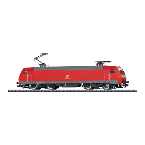
Trix BR 112 User manual

Modell der Elektrolokomotive BR 112
22064
F
D GB USA NL

2

3
Inhaltsverzeichnis Seite
Sicherheitshinweise 4
Wichtige Hinweise 4
Multiprotokollbetrieb 4
Schaltbare Funktionen 7
Parameter/Register 8
Wartung und Instandhaltung 24
Ersatzteile 30
Table of Contents Page
Safety Notes 9
Important Notes 9
Multi-Protocol Operation 9
Controllable Functions 12
Parameter/Register 13
Service and maintenance 24
Spare Parts 30
Sommaire Page
Remarques importantes sur la sécurité 14
Information importante 14
Mode multiprotocole 14
Fonctions commutables 17
Paramètre/Registre 18
Entretien et maintien 24
Pièces de rechange 30
Inhoudsopgave Pagina
Veiligheidsvoorschriften 19
Belangrijke aanwijzing 19
Multiprotocolbedrijf 19
Schakelbare functies 22
Parameter/Register 23
Onderhoud en handhaving 24
Onderdelen 30

4
Sicherheitshinweise
• DieLokdarfnurmiteinemdafürbestimmtenBetriebssys-
tem eingesetzt werden.
• Analogmax.15Volt=,digitalmax.22Volt~.
• DieLokdarfnurauseinerLeistungsquelleversorgt
werden.
• BeachtenSieunbedingtdieSicherheitshinweiseinder
Bedienungsanleitung zu Ihrem Betriebssystem.
• FürdenkonventionellenBetriebderLokmussdasAn-
schlussgleisentstörtwerden.DazuistdasEntstörset
611655zuverwenden.FürDigitalbetriebistdasEntstör-
set nicht geeignet.
• ACHTUNG! Funktionsbedingte scharfe Kanten und Spitzen.
• SetzenSiedasModellkeinerdirektenSonneneinstrah-
lung,starkenTemperaturschwankungenoderhoher
Luftfeuchtigkeitaus.
• VerbauteLED`sentsprechenderLaserklasse1nach
NormEN60825-1.
Wichtige Hinweise
• DieBedienungsanleitungunddieVerpackungsind
BestandteiledesProduktesundmüssendeshalbaufbe-
wahrt sowie bei Weitergabe des Produktes mitgegeben
werden.
• FürReparaturenoderErsatzteilewendenSiesichbittean
IhrenTrix-Fachhändler.
• GewährleistungundGarantiegemäßderbeiliegenden
Garantieurkunde.
• Entsorgung:www.maerklin.com/en/imprint.html
• DervolleFunktionsumfangistnurunterDCCundunter
mfxverfügbar.
• Eingebaute,fahrtrichtungsabhängigeStirnbeleuchtung.
ImDigitalbetriebschaltbar.
• BefahrbarerMindestradius360mm.
• DieLokistnichtaufOberleitungsbetriebumschaltbar.
Multiprotokollbetrieb
Analogbetrieb
DerDecoderkannauchaufanalogenAnlagenoderGleis-
abschnittenbetriebenwerden.DerDecodererkenntdie
analogeGleichspannung(DC)automatischundpasstsich
deranalogenGleisspannungan.EssindalleFunktionen,
dieuntermfxoderDCCfürdenAnalogbetriebeingestellt
wurdenaktiv(sieheDigitalbetrieb).
Digitalbetrieb
DerDecoderisteinMultiprotokolldecoder.DerDecoder
kannunterfolgendenDigital-Protokolleneingesetztwerden:
mfx,DCCoderMM.
AdresseabWerk:DCC 03 / MM 10
DasDigital-ProtokollmitdenmeistenMöglichkeitenistdas
höchstwertigeDigital-Protokoll.DieReihenfolgederDigital-
ProtokolleistinderWertungfallend:
Priorität1:mfx
Priorität2:DCC
Priorität3:MM

5
Hinweis: WerdenzweiodermehrereDigital-Protokolleam
Gleiserkannt,übernimmtderDecoderautomatischdas
höchstwertigeDigital-Protokoll;z.B.wirdmfx&DCCerkannt
wirddasmfx-Digital-ProtokollvomDecoderübernommen.
EinzelneProtokollekönnenüberdenParameterCV50
deaktiviert werden.
Hinweis:BeachtenSie,dassnichtalleFunktioneninallen
Digital-Protokollenmöglichsind.UntermfxundDCCkönnen
einigeEinstellungenvonFunktionen,welcheimAnalog-
Betriebwirksamseinsollen,vorgenommenwerden.
Hinweise zum Digitalbetrieb
• DiegenaueVorgehensweisezumEinstellenderdiversen
Parameter entnehmen Sie bitte der Bedienungsanleitung
Ihrer Mehrzug-Zentrale.
• DerBetriebmitgegenpoligerGleichspannungim
Bremsabschnitt ist mit der werkseitigen Einstellung
nichtmöglich.IstdieseEigenschaftgewünscht,somuss
aufdenkonventionellenGleichstrombetriebverzichtet
werden(CV29/Bit2=0).
mfx-Protokoll
Adressierung
• KeineAdresseerforderlich,jederDecodererhälteine
einmaligeundeindeutigeKennung(UID).
• DerDecodermeldetsichaneinerCentralStationoder
MobileStationmitseinerUIDautomatischan.
• NameabWerk:112 488-2 DB
Programmierung
• DieEigenschaftenkönnenüberdiegrascheOberäche
der Central Station bzw. teilweise auch mit der Mobile
Station programmiert werden.
• EskönnenalleCongurationVariablen(CV)mehrfach
gelesen und programmiert werden.
• DieProgrammierungkannentwederaufdemHaupt-oder
dem Programmiergleis erfolgen.
• DieDefaulteinstellungen(Werkseinstellungen)können
wieder hergestellt werden.
• Funktionsmapping:FunktionenkönnenmitHilfeder
CentralStation60212(eingeschränkt)undmitderCentral
Station60213/60214/60215/60216/60226beliebigenFunkti-
onstastenzugeordnetwerden(sieheHilfeinderCentral
Station).

6
DCC-Protokoll
Adressierung
• MöglicheAdressen:Kurze,langeundTraktionsadresse
• Adressbereich:
1–127(kurzeAdresse,Traktionsadresse)
1–10239(langeAdresse)
• JedeAdresseistmanuellprogrammierbar.
• KurzeoderlangeAdressewirdüberdieCVsausgewählt.
• EineangewandteTraktionsadressedeaktiviertdie
Standard-Adresse.
Programmierung
• DieEigenschaftenkönnenüberdieCongurationsVari-
ablen(CV)mehrfachgeändertwerden.
• DieCV-NummerunddieCV-Wertewerdendirekteinge-
geben.
• DieCVskönnenmehrfachgelesenundprogrammiert
werden(ProgrammierungaufdemProgrammiergleis).
• DieCVskönnenbeliebigprogrammiertwerden.PoM
(ProgrammierungaufdemHauptgleisPoM)istnurbei
deninderCV-TabellegekennzeichnetenCVmöglich.
PoMmussvonIhrerZentraleunterstütztwerden(siehe
BedienungsanleitungihresGerätes).
• DieDefaulteinstellungen(Werkseinstellungen)können
wieder hergestellt werden.
• 14bzw.28/126Fahrstufeneinstellbar.
• AlleFunktionenkönnenentsprechenddemFunktions-
mapping geschaltet werden.
• WeitereInformation,sieheCV-TabelleDCC-Protokoll.
Eswirdempfohlen,dieProgrammierungengrundsätzlichauf
dem Programmiergleis vorzunehmen.
Logische Funktionen
Anfahr-/Bremsverzögerung
• DieBeschleunigungs-undBremszeitkönnengetrennt
von einander eingestellt werden.
• DielogischeFunktionsabschaltungABVkannüberdas
Funktionsmapping auf jede beliebige Funktionstaste
gelegt werden.

7
1 TrixSystems
2Nur in Verbindung mit Spitzensignal /
Zusammengeschaltet:RangierlichtDoppelA.
3 mitZufallsgeräuschen
Schaltbare Funktionen
DC/AC
MS I 1
MS II
CS I
CS II/III
Spitzensignal / Schlusslicht rot F0
Geräusch:Bahnhofsansage1 F1
Betriebsgeräusch3F2
Geräusch:Pfeifelang F3
ABV,aus F4
Geräusch:Bremsenquietschenaus F5
SpitzensignalFührerstand2aus2F6
Geräusch:Rangierpff F7
SpitzensignalFührerstand1aus2F8
Geräusch:Sanden F9
Geräusch:Lüfter F10
Geräusch:Schaffnerpff F11
Geräusch:Kompressor F12
Geräusch:Pressluftablassen F13
Geräusch:Sifa(Alarm) F14
Geräusch:Ankuppeln/Abkuppeln F15
Schaltbare Funktionen
DC/AC
MS I 1
MS II
CS I
CS II/III
Umgebungsgeräusch:Bahnhof1 F16
Geräusch:Bahnhofsansage2 F17
Geräusch:Multihaltestellenansage F18
Umgebungsgeräusch:Bahnhof2 F19

8
CV Bedeutung Wert DCC ab Werk
1Adresse 1 - 127 3
2 PoM Minimalgeschwindigkeit 0-255 4
3 PoM Anfahrverzögerung 0-255 34
4 PoM Bremsverzögerung 0-255 34
5PoM Maximalgeschwindigkeit 0-255 196
8 Werkreset/Herstellerkennung 8 131
13 PoM FunktionenF1-F8imAnalogbetrieb 0-255 0
14 PoM FunktionenF9-F15undLichtimAnalogbetrieb 0-255 1
17 ErweiterteAdresse(obererTeil) CV29,Bit5=1 192
18 ErweiterteAdresse(untererTeil) CV29,Bit5=1 128
19 Traktionsadresse 0-255 0
21 PoM FunktionenF1-F8beiTraktion 0-255 0
22 PoM FunktionenF9-F15undLichtbeiTraktion 0-255 0
29 PoM
Bit0:UmpolungFahrtrichtung
Bit1:AnzahlFahrstufen14oder28/128*
Bit2:DCCBetriebmitBremsstrecke(keinAnalogbetriebmöglich)
Bit5:kurze/langeAdresse
0 / 1
0 / 2
0 / 4
0 / 32
0,1,2,3,4,5,6,7,
32,34,35,36,37,
38,39
6
50 PoM
AlternativeProtokolle(DCCkannsichselbernichtdeaktivieren)
Bit0:AnalogACaus=0/AnalogACein=1
Bit1:AnalogDCaus=0/AnalogDCein=1
Bit2:fx(MM)aus=0/fx(MM)ein=1
Bit3:mfxaus=0/mfxein=1
0 / 1
0 / 2
0 / 4
0 / 8
0-15 15
63 PoM Lautstärke 0-255 255
* FahrstufenamLokdecoderundamSteuergerätmüssenübereinstimmen,essindsonstFehlfunktionenmöglich.

9
• ThefullrangeoffunctionsisonlyavailableunderDCC
andmfx.
• Built-inheadlightsthatchangeoverwiththedirectionof
travel.Theycanbeturnedonandoffindigitaloperation.
• Minimumradiusforoperationis360mm/14-3/16“.
• Thelocomotivecannotbeswitchedtooperationfrom
catenary.
Multi-Protocol Operation
Analog Operation
Thisdecodercanalsobeoperatedonanaloglayoutsorar-
easoftrackthatareanalog.Thedecoderrecognizesalter-
natingcurrent(DC)andautomaticallyadaptstotheanalog
trackvoltage.AllfunctionsthatweresetundermfxorDCC
foranalogoperationareactive(seeDigitalOperation).
Digital Operation
Thedecodersaremulti-protocoldecoders.Thesedecoders
canbeusedunderthefollowingdigitalprotocols:mfx,DCC
or MM.
Addresssetatthefactory:DCC 03 / MM 10
Thedigitalprotocolwiththemostpossibilitiesisthehighest
orderdigitalprotocol.Thesequenceofdigitalprotocolsin
descendingorderis:
Priority1:mfx
Priority2:DCC
Priority3:MM
Note: If two or more digital protocols are recognized in the
track,thedecoderautomaticallytakesonthehighestvalue
digitalprotocol.Forexample,ifmfx&DCCarerecognized,
Safety Notes
• Thislocomotiveisonlytobeusedwiththeoperating
system it is designed for.
• Analogmax.15voltsDC,digitalmax.22voltsAC.
• Thislocomotivemustneverbesuppliedwithpowerfrom
more than one power pack.
• Pleasemakenoteofthesafetynotesintheinstructions
for your operating system.
• Thefeedertrackmustbeequippedtopreventinter-
ferencewithradioandtelevisionreception,whenthe
locomotiveistoberuninconventionaloperation.The
611655interferencesuppressionsetistobeusedforthis
purpose.Theinterferencesuppressionsetisnotsuitable
for digital operation.
• WARNING! Sharp edges and points required for operation.
• Donotexposethemodeltodirectsunlight,extreme
changesintemperature,orhighhumidity.
• TheLEDsinthisitemcorrespondtoLaserClass1accor-
dingtoStandardEN60825-1.
Important Notes
• Theoperatinginstructionsandthepackagingareacom-
ponent part of the product and must therefore be kept as
well as transferred along with the product to others.
• PleaseseeyourauthorizedTrixdealerforrepairsor
spare parts.
• Thewarrantycardincludedwiththisproductspecies
the warranty conditions.
• Disposing:www.maerklin.com/en/imprint.html
10
themfxdigitalprotocolistakenonbythedecoder.Individual
protocolscanbedeactivatedwithParameterCV50.
Note: Please note that not all functions are possible in all
digitalprotocols.Severalsettingsforfunctions,whichare
supposedtobeactiveinanalogoperation,canbedone
undermfxandDCC.
Notes on digital operation
• Theoperatinginstructionsforyourcentralunitwillgive
youexactproceduresforsettingthedifferentparame-
ters.
• Thesettingdoneatthefactorydoesnotpermitoperation
withoppositepolarityDCpowerinthebrakingblock.
Ifyouwantthischaracteristic,youmustdowithout
conventionalDCpoweroperation(CV29/Bit2=0).
mfx Protocol
Addresses
• Noaddressisrequired;eachdecoderisgivenaone-
time,uniqueidentier(UID).
• ThedecoderautomaticallyregistersitselfonaCentral
StationoraMobileStationwithitsUID.
• Namesetatthefactory:112 488-2 DB
Programming
• Thecharacteristicscanbeprogrammedusingthe
graphic screen on the Central Station or also partially
with the Mobile Station.
• AlloftheCongurationVariables(CV)canbereadand
programmed repeatedly.
• Theprogrammingcanbedoneeitheronthemaintrackor
the programming track.
• Thedefaultsettings(factorysettings)canbeproduced
repeatedly.
• Functionmapping:Functionscanbeassignedto
any of the function buttons with the help of the
60212CentralStation(withlimitations)andwiththe
60213/60214/60215/60216/60226CentralStation(Seehelp
sectionintheCentralStation).

11
DCC Protocol
Addresses
• Possibleaddresses:short,long,andm.u.address
• Addressrange:
1–127(shortaddress,m.u.address)
1–10239(longaddress)
• Everyaddresscanbeprogrammedmanually.
• AshortoralongaddressisselectedusingtheCVs.
• Amultipleunitaddressthatisbeinguseddeactivatesthe
standard address.
Programming
• Thecharacteristicscanbechangedrepeatedlyusingthe
CongurationVariables(CV).
• TheCVnumbersandtheCVvaluesareentereddirectly.
• TheCVscanbereadandprogrammedrepeatedly.(Pro-
grammingisdoneontheprogrammingtrack.)
• TheCVscanbeprogrammed,asyoudesire.PoM(Pro-
grammingonthelayouttrack)isonlypossiblewiththose
CVs marked in the CV table. PoM must be supported
byyourcentralcontroller(seetheinstructionsforyour
controller).
• Thedefaultsettings(factorysettings)canbeproduced
repeatedly.
• 14or28/126speedlevelscanbeset.
• Allofthefunctionscanbecontrolledaccordingtothe
functionmapping(seeCVdescription).
• SeetheCVdescriptionfortheDCCprotocolforadditional
information.
We recommend that in general programming should be
done on the programming track.
Logic Functions
Acceleration / Braking Delay
• Theaccelerationandbrakingtimescanbesetseparately
from each other.
• ThelogicalfunctionshutoffforABV(Acceleration/
BrakingDelay)canbeassignedtoanyfunctionbuttonby
means of function mapping.

12
1 TrixSystems
2Only in conjunction with the headlights /
Switchedtogether:„DoubleA“switchinglights.
3with random sounds
Controllable Functions
DC/AC
MS I 1
MS II
CS I
CS II/III
Headlights / Red marker light F0
Soundeffect:Stationannouncements1 F1
Operating sounds 3F2
Soundeffect:Longwhistleblast F3
ABV,off F4
Soundeffect:Squealingbrakesoff F5
Headlights Engineer‘s Cab 2 off 2F6
Soundeffect:Switchingwhistle F7
Headlights Engineer‘s Cab 1 off 2F8
Soundeffect:Sanding F9
Soundeffect:Blower F10
Soundeffect:Conductorwhistle F11
Soundeffect:Compressor F12
Soundeffect:Compressedair F13
Soundeffect:Sifa(alarm) F14
Soundeffect:Coupling/uncoupling F15
Controllable Functions
DC/AC
MS I 1
MS II
CS I
CS II/III
Backgroundsound:Station1 F16
Soundeffect:Stationannouncements2 F17
Soundeffect:Multi-stopannouncement F18
Backgroundsound:Station2 F19

13
* Thespeedlevelsonthelocomotivedecoderandonthecontrollermustagreewitheachother;otherwise,
you may have malfunctions.
CV Discription DCC Value Factory-Set
1Address 1 - 127 3
2 PoM Minimum Speed 0-255 4
3 PoM Accelerationdelay 0-255 34
4 PoM Braking delay 0-255 34
5PoM Maximumspeed 0-255 196
8 Factory Reset / Manufacturer Recognition 8 131
13 PoM Functions F1 - F8 in analog operation 0-255 0
14 PoM FunctionsF9-F15andlightsinanalogoperation 0-255 1
17 Extendedaddress(upperpart) CV29,Bit5=1 192
18 Extendedaddress(lowerpart) CV29,Bit5=1 128
19 MultipleUnitAddress 0-255 0
21 PoM FunctionsF1-F8onMultipleUnit 0-255 0
22 PoM FunctionsF9-F15andlightsonMultipleUnit 0-255 0
29 PoM
Bit0:Reversingdirectionoftravel
Bit1:Numberofspeedlevels14or28/128*
Bit2:DCCoperationwithabrakingarea(noanalogoperation
possible)
Bit5:short/longaddress
0 / 1
0 / 2
0 / 4
0 / 32
0,1,2,3,4,5,6,
7,32,34,35,36,
37,38,39
6
50 PoM
AlternativeProtocols(DCCcannotdeactivateitself)
Bit0:AnalogACoff=0/AnalogACon=1
Bit1:AnalogDCoff=0/AnalogDCon=1
Bit2:fx(MM)off=0/fx(MM)on=1
Bit3:mfxoff=0/mfxon=1
0 / 1
0 / 2
0 / 4
0 / 8
0-15 15
63 PoM Volume 0-255 255

14
Remarques importantes sur la sécurité
• Lalocomotivenepeutêtreutiliséequ‘aveclesystème
d‘exploitationindiqué.
• Analogiquemax.15Volt=,digitalmax.22Volt~.
• Lalocomotivenepeutpasêtrealimentéeélectriquement
par plus d‘une source de courant à la fois.
• Ilestimpératifdetenircomptedesremarquessurla
sécurité décrites dans le mode d‘emploi de votre système
d‘exploitation.
•
Pourl’exploitationdelalocomotiveenmodeconvention-
nel,lavoiederaccordementdoitêtredéparasitée.Acet
effet,utiliserlesetdedéparasitageréf.611655.Lesetde
déparasitageneconvientpaspourl’exploitationenmode
numérique.
•
ATTENTION! Pointes et bords coupants lors du fonctionne-
ment du produit.
• Nepasexposerlemodèleàunensoleillementdirect,
àdefortesvariationsdetempératureouàuntaux
d‘humidité important.
• LesDELinstalléescorrespondentàlaclasselaser1
selonlanormeEN60825-1.
Information importante
• Lanoticed‘utilisationetl’emballagefontpartieintégrante
duproduit;ilsdoiventdoncêtreconservéset,lecas
échéant,transmisavecleproduit.
• Pourtouteréparationouremplacementdepièces,adres-
sezvousàvotredétaillant-spécialisteTrix.
• Garantielégaleetgarantiecontractuelleconformément
aucerticatdegarantieci-joint.
• Elimination:www.maerklin.com/en/imprint.html
• L’intégralitédesfonctionsestdisponibleuniquementen
exploitationDCCetmfx.
• Feuxdesignalisations‘inversantselonlesensdemar-
che;feuxcommutablesenexploitationdigital.
• Rayonminimald’inscriptionencourbe360mm.
• Lalocomotivenepeutpasêtreexploitéesouscaténaire.
Mode multiprotocole
Mode analogique
On peut aussi faire fonctionner le décodeur sur des instal-
lationsoudessectionsdevoieanalogiques.Ledécodeur
identieautomatiquementlatensiondevoieanalogique
(DC).Touteslesfonctionsquiontétéparamétréepourle
modeanalogiquesousmfxousousDCCsontactives(voir
modenumérique).
Mode numérique
Lesdécodeursontdesdécodeurmultiprotocole.Le
décodeurpeutêtreutiliséaveclesprotocolesnumériques
suivants:mfx,DCC,MM
Adresseencodéeenusine:DCC 03 / MM 10
Leprotocolenumériqueoffrantlespossibilitéslesplus
nombreuses est le protocole numérique à bit de poids
fort.Lahiérarchisationdesprotocolesnumériquesest
descendante:
Priorité1:mfx
Priorité2:DCC
Priorité3:MM

15
Indication :Sideuxouplusdedeuxprotocolesnumériques
sontreconnussurlavoie,ledécodeurchoisitautomatique-
mentleprotocolenumériqueleplussignicatif.Entreles
protocolesmfx&DCCparexemple,ledécodeurchoisira
leprotocolenumériquemfx.Vouspouvezdésactiverles
différentsprotocolesvialeparamètreCV50.
Indication : remarquez que toutes les fonctions ne peuvent
pasêtreactionnéesdanstouslesprotocolesnumériques.
SousmfxetsousDCC,ilestpossibledeprocéderà
quelquesparamétragesdefonctionsdevantêtreactives
danslecadredel’exploitationanalogique.
Remarques relatives au fonctionnement en mode digital
• Encequiconcernelaprocédurederéglagedesdivers
paramètres,veuillezvousréféreraumoded‘emploide
votre centrale de commande multitrain.
• L’exploitationaveccourantcontinudepolaritéinverse
dans les sections de freinage n’est pas possible avec
leréglaged’usine.Sicettepropriétéestdésirée,ilfaut
alorsrenonceràl’exploitationconventionnelleencou-
rantcontinu(CV29/Bit2=0).
Protocole mfx
Adressage
• Aucuneadressen’estnécessaire,ledécodeurreçoittou-
tefoisuneidenticationuniqueetnonéquivoque(UID).
• AvecsonUID,ledécodeurindiqueautomatiquement
à une station centrale ou à une station mobile qu’il est
connecté.
• Nomencodeeenusine:112 488-2 DB
Programmation
• Lescaractéristiquespeuventêtreprogramméespar
l’intermédiaire de la couche graphique de la station cen-
trale,voireenpartieaussiaumoyendelastationmobile.
• Touteslescongurationsvariables(CV)peuventêtrelues
etprogramméesdefaçonréitérée.
• Laprogrammationpeutêtreréaliséesoitsurlavoie
principale,soitsurlavoiedeprogrammation.
• Lesparamétragespardéfaut(paramétragesusine)
peuventêtrerétablis.
• Mappagedesfonctions:lesfonctionspeuventêtre
affectées à de quelconques touches de fonction au
moyendelastationcentrale(60212)(restreinte)etavec
lastationcentrale60213/60214/60215/60216/60226(voir
Aideauniveaudelastationcentrale).

16
Protocole DCC
Adressage
• Adressepossibles:Courtes,longuesetadressesdetraction
• Catégoried’adresse:
1à127(adressescourtes,adressesdetraction)
1à10239(adresseslongues)
• Chaqueadresseestprogrammablemanuellement.
• L’adressebrèveoulongueestchoisieparl’intermédiaire
des CVs.
• Uneadressedetractionutiliséedésactivel’adresse
standard.
Programmation
• Lescaractéristiquespeuventêtremodiéesdefaçon
réitéréeparl’intermédiairedesvariablesdeconguration
(CVs).
• Touteslescongurationsvariables(CV)peuventêtrelues
etprogramméesdefaçonréitérée.
• Laprogrammationpeutêtreréaliséesoitsurlavoie
principale,soitsurlavoiedeprogrammation.
• LesCVpeuventêtreprogramméeslibrement.LaPoM
(programmationsurlavoieprincipale)estpossible
uniquement pour les CV signalées dans le tableau des CV.
LaPoMdoitêtrepriseenchargeparvotrecentrale(voir
lanoticed’utilisationdevotreappareil).
• Lesparamétragespardéfaut(paramétragesusine)
peuventêtrerétablis.
• 14voire28/126cransdemarchesontparamétrables.
• Touteslesfonctionspeuventêtrecommutéesenfonction
dumappagedesfonctions(voirledescriptifdesCVs).
• Pourtouteinformationcomplémentaire,voirletableau
desCVs,protocoleDCC.
Ilestrecommandé,deréaliserlaprogrammation,fonda-
mentalement,surlavoiedeprogrammation.
Fonctions logiques
Temporisation d’accélération et de freinage (TAF)
• Lestempsd’accélérationetdefreinagepeuventêtre
dénisindépendammentl’undel’autre.
• LadésactivationdelafonctionlogiqueTAFpeutêtre
affectée à n’importe quelle touche de fonction via le
mappage de fonctions.

17
1 TrixSystems
2 Uniquementencombinaisonaveclefanal/
Commutéssimultanément:feuxdemanœuvredoubleA.
3avec bruits aléatoires
Fonctions commutables
DC/AC
MS I 1
MS II
CS I
CS II/III
Fanal/Feudendeconvoirouge F0
Bruitage:Annonceengare1 F1
Bruitd’exploitation3F2
Bruitage:sifetlongueur F3
ABV,désactivé F4
Bruitage:Grincementdefreins
désactivé F5
Fanal cabine de conduite 2 éteint 2F6
Bruitage:Sifetpourmanœuvre F7
Fanal cabine de conduite 1 éteint 2F8
Bruitage:Sablage F9
Bruitage:Ventilateur F10
Bruitage:SifetContrôleur F11
Bruitage:Compresseur F12
Bruitage:Aircomprimé F13
Bruitage:Sifa(alarme) F14
Bruitage:Attelage/Déconnecter F15
Fonctions commutables
DC/AC
MS I 1
MS II
CS I
CS II/III
Bruitageambiant:Gare1 F16
Bruitage:Annonceengare2 F17
Bruitage:Annoncemultipleengare F18
Bruitageambiant:Gare2 F19

18
CV Affectation DCC Valeur Parm. Usine
1Adresse 1 - 127 3
2 PoM Vitesse minimale 0-255 4
3 PoM Temporisationd‘accélération 0-255 34
4 PoM Temporisationdefreinage 0-255 34
5PoM Vitessemaximale 0-255 196
8Réinitialisationd’usine/identicationdufabricant 8 131
13 PoM Fonctions F1 - F8 en mode analogique 0-255 0
14 PoM FonctionsF9-F15etéclairageenmodeanalogique 0-255 1
17 Adresseétendue(partiesupérieure) CV29,Bit5=1 192
18 Adresseétendue(partieinférieure) CV29,Bit5=1 128
19 Adressetraction 0-255 0
21 PoM Fonctions F1 - F8 pour traction 0-255 0
22 PoM FonctionsF9-F15etéclairagetraction 0-255 0
29 PoM
Bit0:Inversiondusensdemarche
Bit1:Nombredecransdemarche14ou28/128*
Bit2:ExploitationDCCavecsectiondefreinage(exploitation
analogiqueimpossible)
Bit5:Adressecourte/longue
0 / 1
0 / 2
0 / 4
0 / 32
0,1,2,3,4,5,6,
7,32,34,35,36,
37,38,39
6
50 PoM
Autresprotocoles(DCCnepeutpassedésactiverlui-même)
Bit0:AnalogiqueCAhorsfonction=0/analogiqueCAenfonction=1
Bit1:AnalogiqueCChorsfonction=0/analogiqueCCenfonction=1
Bit2:fx(MM)horsfonction=0/fx(MM)enfonction=1
Bit3:mfxhorsfonction=0/mfxenfonction=1
0 / 1
0 / 2
0 / 4
0 / 8
0-15 15
63 PoM Volume 0-255 255
* Pourévitertoutdysfonctionnement,lescransdemarchesurledécodeurdelocodoiventimpérativement
coïncideravecceuxdel’appareildecommande.

19
Veiligheidsvoorschriften
• Delocmagalleenmeteendaarvoorbestemdbedrijfssys-
teem gebruikt worden.
• Analoogmax.15Volt=,digitaalmax.22Volt~.
• Delocmagnietvanuitmeerdanéénstroomvoorziening
gelijktijdig gevoed worden.
• Leesookaandachtigdeveiligheidsvoorschrifteninde
gebruiksaanwijzing van uw bedrijfssysteem.
• Voorhetconventionelebedrijfmetdelocdientde
aansluitrail te worden ontstoort. Hiervoor dient men de
ontstoor-set611655tegebruiken.Voorhetdigitalebedrijf
is deze ontstoor-set niet geschikt.
• OPGEPAST! Functionele scherpe kanten en punten.
• Stelhetmodelnietblootaanindirectezonnestraling,
sterke temperatuurwisselingen of hoge luchtvochtigheid.
• IngebouwdeLED’skomenovereenmetdelaserklasse1
volgensdenormEN60825-1.
Belangrijke aanwijzing
• Degebruiksaanwijzingendeverpakkingzijneenbe-
standdeel van het product en dienen derhalve bewaard
en meegeleverd te worden bij het doorgeven van het
product.
• VoorreparatiesenonderdelenkuntzichtotUwTrix
handelaar wenden.
• Vrijwaringengarantieovereenkomstighetbijgevoegde
garantiebewijs.
• Afdanken:www.maerklin.com/en/imprint.html
• Devolledigetoegangtotallefunctiesisalleenmogelijk
metDCCofmetmfxbedrijf.
• Ingebouwde,rijrichtingsafhankelijkefrontverlichtingisin
het digitaalsysteem schakelbaar.
• Minimaleteberijdenradius:360mm.
• Delockannietomgeschakeldwordenopbovenleiding.
Multiprotocolbedrijf
Analoogbedrijf
Dedecoderkanookopanalogemodelbanenofspoortra-
jectengebruiktworden.Dedecoderherkentdeanaloge
gelijkspanning(DC)automatischenpastzichaande
analogerailspanningaan.AllefunctiesdieondermfxofDCC
voorhetanalogebedrijfzijningesteld,wordengeactiveerd
(ziedigitaalbedrijf).
Digitaalbedrijf
DeDecoderiseenmultiprotocoldecoder.Dedecoderkan
onderdevolgendedigitaleprotocolleningezetworden:mfx,
DCC,MM.
Vanafdefabriekingesteld:DCC 03 / MM 10
Het digitaalprotocol met de meeste mogelijkheden is het
primairedigitaalprotocol.Devolgordevandedigitaalproto-
collenisafnemendinmogelijkheden:
Prioriteit1:mfx
Prioriteit2:DCC
Prioriteit3:MM
Opmerking:Alsertweeofmeerdigitaleprotocollenop
derailswordenherkend,danneemtdedecoderautoma-
tischhethoogwaardigsteprotocolover;bijv.wordmfx&
DCCherkend,danwordthetmfxsignaaldoordedecoder
overgenomen.Deverschillendeprotocollenkunnenviade

20
parameterCV50gedeactiveerdworden.
Opmerking: let er op dat niet alle functies in alle digitaal-
protocollenmogelijkzijn.OndermfxofDCCkunnenenkele
instellingen,welkeinanaloogbedrijfwerkzaammoetenzijn,
ingesteld worden.
Aanwijzingen voor digitale besturing
• Hetopdejuistewijzeinstellenvandediverseparame-
ters staat beschreven in de handleiding van uw digitale
Centrale.
• Hetbedrijfmettegengepooldegelijkspanningindeafrem-
sectie is met de fabrieksinstelling niet mogelijk. Indien deze
eigenschapwenselijkis,danmoetwordenafgezienvan
hetconventioneelgelijkstroombedrijf(CV29/Bit2=0).
mfx-protocol
Adressering
• Eenadresisnietnodig,elkedecoderheefteenéénmalig
enéénduidigkenmerk(UID).
• DedecodermeldtzichvanzelfaanbijhetCentralStation
ofMobileStationmetzijnUID.
• Naamafdefabriek:112 488-2 DB
Programmering
• Deeigenschappenkunnenm.b.v.hetgraschescherm
op het Central Station resp. deels ook met het Mobile
Station geprogrammeerd worden.
• Alleconguratievariabelen(CV)kunnenvakergelezen
en geprogrammeerd worden.
• Deprogrammeringkanzowelophethoofdspooralsop
het programmeerspoor gebeuren.
• Dedefault-instellingen(fabrieksinstelling)kunnenweer
hersteld worden.
• Functiemapping:functieskunnenmetbehulpvanhet
CentralStation60212(metbeperking)enmethet
CentralStation60213/60214/60215/60216/60226aanelke
gewenstefunctietoetswordentoegewezen(ziehet
helpbestandinhetCentralStation).
Other manuals for BR 112
1
Table of contents
Languages:
Other Trix Toy manuals

Trix
Trix minitrix Re 460 User manual

Trix
Trix Minitrix BD D 220 User manual

Trix
Trix 22293 User manual

Trix
Trix ICE 3 User manual

Trix
Trix H0 BR E 10.3 User manual

Trix
Trix Minitrix 66300 User manual

Trix
Trix H0 Kof II User manual

Trix
Trix E-Lok Ae 8/14 User manual

Trix
Trix BR 89.70-75 22146 User manual

Trix
Trix BR 03 Altbau User manual