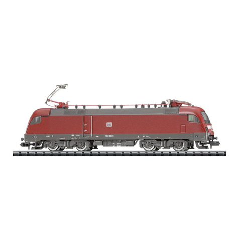
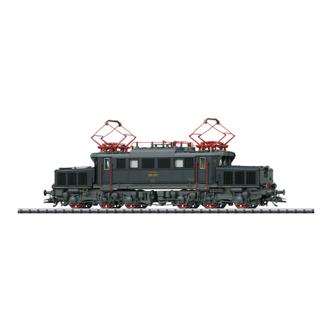
Trix MINITRIX 16661 User manual

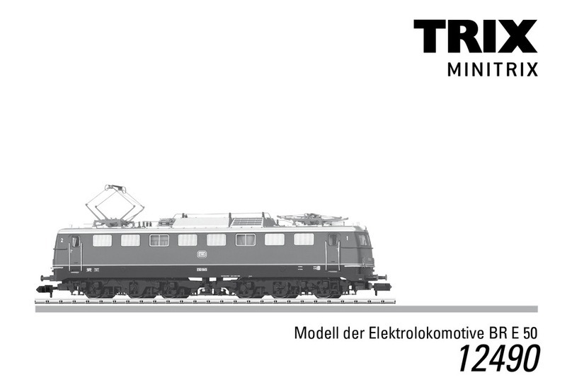
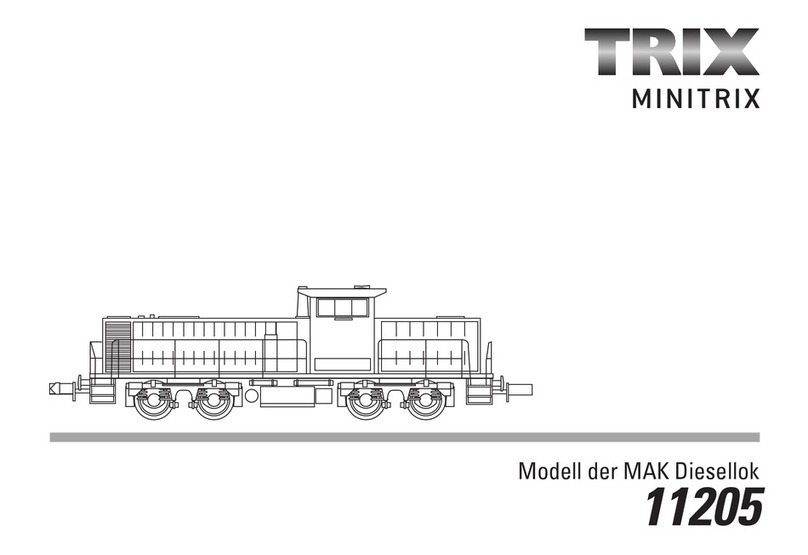
Modell der Elektrolokomotive BR E44
16661
D GB USA F

2

3
Inhaltsverzeichnis: Seite
Informationen zum Vorbild 4
Sicherheitshinweise 6
Wichtige Hinweise 6
Funktionen 6
Hinweise zum Digitalbetrieb 6
Schaltbare Funktionen 7
Configurations Variablen (CVs) 8
Wartung und Instandhaltung 18
Ersatzteile 22
Table of Contents: Page
Information about the prototype 4
Safety Notes 10
Important Notes 10
Functions 10
Notes on digital operation 10
Controllable Functions 11
Configuration Variables (CVs) 12
Service and maintenance 18
Spare Parts 22
Sommaire : Page
Informations concernant le modèle réelle 5
Remarques importantes sur la sécurité 14
Information importante 14
Fonctionnement 14
Remarques relatives au fonctionement en mode digital 14
Fonctions commutables 15
Variables de configuration (CVs) 16
Entretien et maintien 18
Pièces de rechange 22

4
Informationen zum Vorbild
Nach einer Unterbrechung durch die große Wirtschaftskrise
wurde ab 1930 die Elektrifizierung des Reichsbahn-Netzes
wieder vorangetrieben. Für die neuen Strecken wurden neue
leistungsfähige Lokomotiven benötigt. In der Zwischenzeit hatte
die deutsche Eisenbahnindustrie Konzepte und Prototypen für
moderne Universallokomotiven entwickelt.
Die Konstruktion von Siemens zeigte deutliche Fortschritte
gegenüber den zuvor nur weiter entwickelten Länderbahn-
Konstruktionen. Die als leichte Universallokomotive konzipierte
Maschine war auf einem geschweißten Rahmen aufgebaut,
auf Drehgestellen mit integrierter Pufferbohle gelagert und mit
Tatzlager-Motoren auf den Achsen angetrieben. Die modernen
Motoren leisteten 2.200 kW, die ohne aufwändige Mechanik
direkt an den Achsen verfügbar waren. Auf ebener Strecke
wurden 90 km/h erreicht.
Die erste Maschine wurde mit Erfolg getestet und noch 1930 von
der Reichsbahn als E 44 001 übernommen. Weitere Lokomotiven
in Serienausführung mit 80 km/h Höchstgeschwindigkeit wurden
umgehend bestellt, zunächst für die Strecke Stuttgart – Augs-
burg (mit der Geislinger Steige). Die Reichsbahn hatte insgesamt
174 Serienloks beschafft, von denen 45 in Ostdeutschland geblie-
ben sind, die meisten übrigen im Westen.
Information about the prototype
After an interruption due to the great economic crisis, the elec-
trification of the German State Railroad’s network was continued
starting in 1930. New, powerful locomotives were needed for the
new routes. In the meantime the German railroad industry had
developed new concepts and prototypes for modern general
purpose locomotives.
This design from Siemens shows clear progress compared to
the provincial railroad designs of before that had been merely
developed further. This unit was designed as a general purpose
locomotive and was built on a welded frame, mounted on trucks
with integrated buffer beams and powered with axlesuspended
motors. The modern motors put out 2200 kilowatts (2950 horsepo-
wer) that was available directly to the axles without the need for
an expensive mechanism. The maximum speed reached on level
track was 90 km/h (56 mph).
The first unit was successfuly tested and placed into service
by the German State Railroad as early as 1930 as the E 44 001.
Additional, regular production locomotives with a maximum
speed of 80 km/h (50 mph) were ordered immediately, initially for
the route from Stuttgart to Augsburg (with the Geislingen Grade).
The German State Railroad purchased a total of 174 regular
production locomotives, of which 45 remained in East Germany
with most of the rest in the West.

5
Informations concernant le modèle réel
Après une interruption due à la grande crise économique,
l’électrification des lignes de la Reichsbahn a repris à partir de
1930. Afin de desservir les nouvelles lignes électrifiées, la DRG
avait besoin de nouvelles et puissantes machines électriques.
Or, l’industrie ferroviare allemande avait entre-temps dévelopé
des concepts et des prototypes pour de nouvelles locomotives
universelles modernes.
La réalisation de Siemens montre le progrès indéniable fait dans
ce domaine quand on la compare aux locomotives fabriquées
auparavant par les chemins de fer régionaux. Cette locomotive
légère universelle comportait un châssis soudé, des bogies avec
traverses porte-tampons intégrées et des moteurs suspendus
par le nez attaquant directment les essieux. Les modernes
moteurs transmettaient directement aux essieux leur 2200 kW de
puissance sans mécanisme de transmission complexe. Sur lignes
plates, la locomotive atteignait la vitesse de pointe de 90 km/h.
La première machine a été testée avec succès et reprise en
écritures à la Reichsbahn en 1930 sous le matricule E 44 001. Une
série d‘autres locomotives capables de rouler à 80 km/h ont été
immédiatement commandées pour desservir dans un premier
temps la ligne Stuttgart – Augsburg (sur laquelle se trouvait la
fameuse Geislinger Steige). La Reichsbahn a en tout passé com-
mande de 174 locomotives dont 45 exemplaires sont restès aprés
1945 en Allemagne de l’Est et le reste en République Fédérale.

6
Sicherheitshinweise
• DieLokdarfnurmiteinemdafürbestimmtenBetriebssystem
eingesetzt werden.
• DieLokdarfnichtmitmehralseinerLeistungsquelleversorgt
werden.
• BeachtenSieunbedingtdieSicherheitshinweiseinder
Bedienungsanleitung zu Ihrem Betriebssystem.
• Analog14Volt=,digital22Volt~.
• FürdenkonventionellenBetriebderLokmussdasAnschluss-
gleis entstört werden. Dazu ist das Entstörset 14972 zu ver-
wenden. Für Digitalbetrieb ist das Entstörset nicht geeignet.
• SetzenSiedasModellkeinerdirektenSonneneinstrahlung,star-
ken Temperaturschwankungen oder hoher Luftfeuchtigkeit aus.
• DasverwendeteGleisanschlusskabeldarfmaximal
2 Meter lang sein.
• ACHTUNG! Funktionsbedingte scharfe Kanten und Spitzen.
• VerbauteLED`sentsprechenderLaserklasse1nachNorm
EN 60825-1.
Wichtige Hinweise
• DieBedienungsanleitungunddieVerpackungsindBestand-
teile des Produktes und müssen deshalb aufbewahrt sowie
bei Weitergabe des Produktes mitgegeben werden.
• FürReparaturenoderErsatzteilewendenSiesichbittean
Ihren Trix-Fachhändler.
• GewährleistungundGarantiegemäßderbeiliegendenGaran-
tieurkunde.
• Entsorgung:www.maerklin.com/en/imprint.html
Funktionen
• EingebauteElektronikzumwahlweisenBetriebmit
konventionellem Gleichstrom-Fahrgerät (max. ±12 Volt),
Trix Systems, Trix Selectrix (SX1) und Selectrix 2 (SX2) oder
Digitalsystemen nach NMRA-Norm.
• AutomatischeSystemerkennungzwischenDigital-und
Analog-Betrieb.
• KeineautomatischeSystemerkennungzwischendenDigital-
Systemen.
• Dreilicht-Spitzensignalvorne,zweiroteSchlusslichterhinten,
mit der Fahrtrichtung wechselnd.
• MitKinematikfürKurzkupplungundKupplungsaufnahme
nach NEM.
• DieLokistnichtaufOberleitungsbetriebumschaltbar.
Hinweise zum Digitalbetrieb
• BeimerstenBetriebineinemDigital-System(SX1,SX2oder
DCC) muss der Decoder auf dieses Digital-System eingestellt
werden. Dazu ist der Decoder einmal in diesem Digitalsystem
zu programmieren (z.B. Adresse ändern).
• DerBetriebmitgegenpoligerGleichspannungimBremsab-
schnitt ist mit der werkseitigen Einstellung nicht möglich. Ist
diese Eigenschaft gewünscht, so muss auf den konventio-
nellen Gleichstrombetrieb verzichtet werden
(DCC:CV29/Bit2=0).

7
Schaltbare Funktionen
Spitzensignal fahrtrichtungsabhängig an F0
Führerstandsbeleuchtung — —F1
Direktsteuerung (ABV) — — — F4
Spitzensignal Führerstand 2 — — — F6
Spitzensignal Führerstand 1 — — — F8
Rangierlicht doppel A — — — F0 + F6 + F8
2
7
1
6
STOP
PR
3
8
Sx
5
ON
Lz
4
9
1/2
Central-Control
66800 f0 - f3 f4 - f7
STOP mobile station
15

8
CV Bedeutung Wert DCC ab Werk
1 Adresse 1 – 127 3
2 Minimalgeschwindigkeit 0 – 15 10
3 Anfahrverzögerung 0 – 255 3
4 Bremsverzögerung 0 – 255 5
5 Maximalgeschwindigkeit 0 – 127 53
17 ErweiterteAdresse(obererTeil)(CV29,Bit5=1) 0 – 255 192
18 ErweiterteAdresse(untererTeil)(CV29,Bit5=1) 0 – 255 0
19 Traktionsadresse(0=inaktiv,Wert+128=inverseFahrtrichtung) 0 – 127 0
21 Traktions-Modus; Bit 0 – 7
=
^
F1 – F8 0 – 255 0
22 Traktions-Modus; Bit 0 – 1
=
^
FLf – FLr, Bit 2 – 5
=
^
F9 – F12 0 – 63 0
29
Bit0:UmpolungFahrtrichtung
Bit1:AnzahlFahrstufen14-28/126
Bit2:DCCBetriebmitBremsstrecke
DCC-, Selectrix- und Gleichstrombetrieb
Bit5:Adressumfang7Bit/14Bit
0 – 255 6

9
par Bedeutung Wert SX2 ab Werk
001 Adresse Einer- u. Zehner-Stelle 0 – 99 1
002 Adresse Hunderter- u. Tausender-Stelle 0 – 99 10
011 Anfahrverzögerung 0 – 255 3
012 Bremsverzögerung 0 – 255 5
013 Maximalgeschwindigkeit 0 – 127 53
014 Mindestgeschwindigkeit 0 – 15 10
018 Geschwindigkeit Rangiergang 0 – 127 53
021 Bremsabschnitte; 1 oder 2 0, 1 0
081 Dimmung Licht normal 0 – 31 31
082 Dimmung Licht alternativ 0 – 31 15
WerkseinstellungfürSX1:01-542,erweitert:00-274

10
Functions
• Built-inelectroniccircuitforoptionaloperationwith
a conventional DC train controller (max. ±12 volts),
Trix Systems, Trix Selectrix (SX1), and Selectrix 2 (SX2),
or digital systems adhering to the NMRA standards.
• Automaticsystemrecognitionbetweendigitalandanalog
operation.
• Noautomaticsystemrecognitionbetweenthedigitalsys-
tems.
• Tripleheadlightsinthefront,dualredmarkerlightsinthe
rear, that change over with the direction of travel.
• NEMclosecouplermechanismandcouplerpocket.
• Thelocomotivecannotbeswitchedtooperationfromcatenary.
Notes on digital operation
• Whenoperatinginadigitalsystemforthersttime(SX1,SX2,
or DCC), the decoder must be set to this digital system. To do
this, the decoder must be programmed once in this digital
system(example:changetheaddress).
• Thesettingdoneatthefactorydoesnotpermitoperationwith
opposite polarity DC power in the braking block. If you want
this characteristic, you must do without conventional DC
poweroperation(DCC:CV29/Bit2=0).
Safety Notes
• Thislocomotiveisonlytobeusedwiththeoperatingsystem
it is designed for.
• Thislocomotivemustnotbesuppliedwithpowerfrommore
than one power pack.
• Paycloseattentiontothesafetynotesintheinstructionsfor
your operating system.
• Analog14voltsDC,digital22voltsAC.
• Thefeedertrackmustbeequippedtopreventinterference
with radio and television reception, when the locomotive is to
be run in conventional operation. The 14972 interference sup-
pression set is to be used for this purpose. The interference
suppression set is not suitable for digital operation.
• Donotexposethemodeltodirectsunlight,extremechanges
in temperature, or high humidity.
• Thewireusedforfeederconnectionstothetrackmaybea
maximum of 2 meters / 78 inches long.
• WARNING! Sharp edges and points required for operation.
• TheLEDsinthisitemcorrespondtoLaserClass1according
to Standard EN 60825-1.
Important Notes
• Theoperatinginstructionsandthepackagingareacompo-
nent part of the product and must therefore be kept as well as
transferred along with the product to others.
• PleaseseeyourauthorizedTrixdealerforrepairsorspareparts.
• Thewarrantycardincludedwiththisproductspeciesthe
warranty conditions.
• Disposing:www.maerklin.com/en/imprint.html

11
Controllable Functions
Headlights on F0
Engineer‘s cab lighting — —F1
Direct control (ABV) — — — F4
Headlights Engineer‘s Cab 2 — — — F6
Headlights Engineer‘s Cab 1 — — — F8
Double A switching light — — — F0 + F6 + F8
2
7
1
6
STOP
PR
3
8
Sx
5
ON
Lz
4
9
1/2
Central-Control
66800 f0 - f3 f4 - f7
STOP mobile station
15

12
CV Discription DCC Value Factory
Setting
1 Address 1 – 127 3
2 Minimum Speed 0 – 15 10
3 Acceleration delay 0 – 255 3
4 Braking delay 0 – 255 5
5 Maximum speed 0 – 127 53
17 Extendetaddress(upperpart)(CV29,Bit5=1) 0 – 255 192
18 Extendetaddress(lowerpart)(CV29,Bit5=1) 0 – 255 0
19 Consistaddress(0=inactive,Value+128=inversedirection) 0 – 127 0
21 Motive Power Mode; Bit 0 – 7
=
^
F1 – F8 0 – 255 0
22 Motive Power Mode; Bit 0 – 1
=
^
FLf – FLr, Bit 2 – 5
=
^
F9 – F12 0 – 63 0
29
Bit0:Traveldirectionpolarityreversal
Bit1:numberofspeedlevels14–28/126
Bit2:DCCOperationwithbrakingBlock
DCC-, Selectrix and DC power operation
Bit5:addresssize7Bit/14Bit
0 – 255 6

13
par Discription SX2 Value Factory
Setting
001 Address for one and ten placeholder 0 – 99 1
002 Address for hundred and thousand placeholder 0 – 99 10
011 Acceleration delay 0 – 255 3
012 Braking delay 0 – 255 5
013 Maximum speed 0 – 127 53
014 Minimum speed 0 – 15 10
018 Speed for switching range 0 – 127 53
021 Braking section; 1 or 2 0, 1 0
081 Dimming of lights, normal 0 – 31 31
082 Dimming of lights, alternative 0 – 31 15
FactorysettingforSX1:01-542,advanced:00-774

14
Remarques importantes sur la sécurité
• Lalocomotivenepeutêtreutiliséequ‘aveclesystème
d‘exploitation indiqué.
• Lalocomotivenepeutêtrealimentéeencourantqueparune
seule source de courant.
• Veuillezimpérativementrespecterlesremarquessurla
sécurité décrites dans le mode d’emploi en ce qui concerne
le système d’exploitation.
• Analogique15volts=,digital22volts~.
• Pourl’exploitationdelalocomotiveenmodeconventionnel,
lavoiederaccordementdoitêtredéparasitée.Aceteffet,uti-
liser le set de déparasitage réf. 14972. Le set de déparasitage
ne convient pas pour l’exploitation en mode numérique.
• Nepasexposerlemodèleàunensoleillementdirect,àdefortes
variations de température ou à un taux d‘humidité important.
• Lecâblederaccordementàlavoieutilisénedoitenaucun
cas dépasser deux mètres.
• ATTENTION! Pointes et bords coupants lors du fonctionne-
ment du produit.
• LesDELinstalléescorrespondentàlaclasselaser1selonla
norme EN 60825-1.
Information importante
• Lanoticed‘utilisationetl’emballagefontpartieintégrantedu
produit;ilsdoiventdoncêtreconservéset,lecaséchéant,
transmis avec le produit.
• Pourtouteréparationouremplacementdepièces,adressez
vous à votre détaillant-spécialiste Trix.
• Garantielégaleetgarantiecontractuelleconformémentau
certificat de garantie ci-joint.
• Elimination:www.maerklin.com/en/imprint.html
Fonctionnement
•
Module électronique intégré pour exploitation au choix avec
régulateur de marche conventionnel c.c. (max. ±12 volts), Trix
Systems, Trix Selectrix (SX1) et Selectrix 2 (SX2) ou systèmes
numériques conformes à la norme NMRA.
• Reconnaissanceautomatiquedusystèmeentreexploitations
numérique et analogique.
• Pasdereconnaissanceautomatiquedusystèmeentreles
systèmes numériques.
• Feuxdesignalisationtriplesàl‘avant,deuxfeuxrouges
de fin de convoi à l‘arrière avec inversion selon sens de
marche.
• AvecboîtiernormaliséNEMàélongationpourattelage
court.
• Lalocomotivenepeutpasêtreexploitéesouscaténaire.
Remarques relatives au fonctionnement en mode digital
• Unepremièreexploitationensystèmenumérique(SX1,SX2
ou DCC) exige un réglage correspondant du décodeur. A
ceteffet,ledécodeurdoitêtreprogramméunefoisdansce
système numérique (modification de l’adresse par ex.).
•
L’exploitation avec courant continu de polarité inverse dans
les sections de freinage n’est pas possible avec le réglage
d’usine. Si cette propriété est désirée, il faut alors renoncer à
l’exploitation conventionnelle en courant continu
(DCC:CV29/Bit2=0).

15
Fonctions commutables
Fanal éclairage activé F0
Eclairage de la cabine de conduite — —F1
Temporisation d’accélération et de freinage — — — F4
Fanal cabine de conduite 2 — — — F6
Fanal cabine de conduite 1 — — — F8
Feu de manœuvre double A — — — F0 + F6 + F8
2
7
1
6
STOP
PR
3
8
Sx
5
ON
Lz
4
9
1/2
Central-Control
66800 f0 - f3 f4 - f7
STOP mobile station
15

16
CV Signification Valeur DCC Valeur Parm. Usine
1 Adresse 1 – 127 3
2 Vitesse min 0 – 15 10
3 Temporisation d‘accélération 0 – 255 3
4 Temporisation de freinage 0 – 255 5
5 Vitesse maximale 0 – 127 53
17 Adresseétendue(partiesupérieure)(CV29,Bit5=1) 0 – 255 192
18 Adresseétendue(partieinférieure)(CV29,Bit5=1) 0 – 255 0
19 Adressepourlatraction(0=inactif,Valeur+128=directioninverse) 0 – 127 0
21 Mode traction, bit 0 à 7
=
^
F1 à F8 0 – 255 0
22 Mode traction; bit 0 à 1
=
^
FLf à FLr, Bit 2 à 5
=
^
F9 à F12 0 – 63 0
29
Bit0:inversiondepolarité,sensdemarche
Bit1:Nombredecransdemarche14–28/126
Bit2:ExploitationDCCaveczonedefreinage.
DCC-, Selectrix et courant continu
Bit5:tailled‘adresse7Bits/14Bits
0 – 255 6

17
par Signification Valeur SX2 Valeur Parm. Usine
001 Adresse unités et décimales 0 – 99 1
002 Adresse centaines et milliers 0 – 99 10
011 Temporisation d’accélération 0 – 255 3
012 Temporisation de freinage 0 – 255 5
013 Vitesse maximale 0 – 127 53
014 Vitesse minimale 0 – 15 10
018 Vitesse de manoeuvre 0 – 127 53
021 Sections de freinage, 1 ou 2 0, 1 0
081 Variation lumière normale 0 – 31 31
082 Variation lumière alternative 0 – 31 15
Paramètresd’usinepourSX1:01à542,étendus:00à774

18
66626Märklin
7149
7149
40h
MINITRIX
66623

19
a
a
a
a
b

20
a
b
b
Table of contents
Languages:
Other Trix Toy manuals

Trix
Trix H0 694 Series User manual

Trix
Trix MINITRIX User manual

Trix
Trix Minitrix 66322 User manual

Trix
Trix BR 420 User manual

Trix
Trix RAB User manual

Trix
Trix BR 403 User manual

Trix
Trix H0 44 Series User manual

Trix
Trix MINITRIX R 3/3 User manual

Trix
Trix Minitrix BR 152 User manual

Trix
Trix BR 80 User manual
Popular Toy manuals by other brands

Seagull Models
Seagull Models P-47D Thunderbolt 60 Assembly manual

Black Horse Model
Black Horse Model Matrix Instruction manual book

Direct Connection RC
Direct Connection RC Kaos Build instructions

pline
pline NDM6 owner's manual

K'Nex Education
K'Nex Education 79014 manual

GRAUPNER
GRAUPNER ACRO MAXIE Building instructions