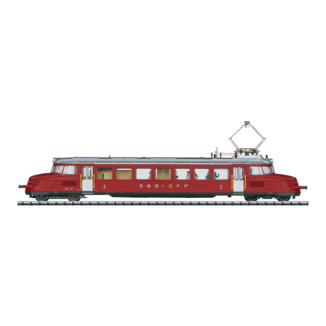
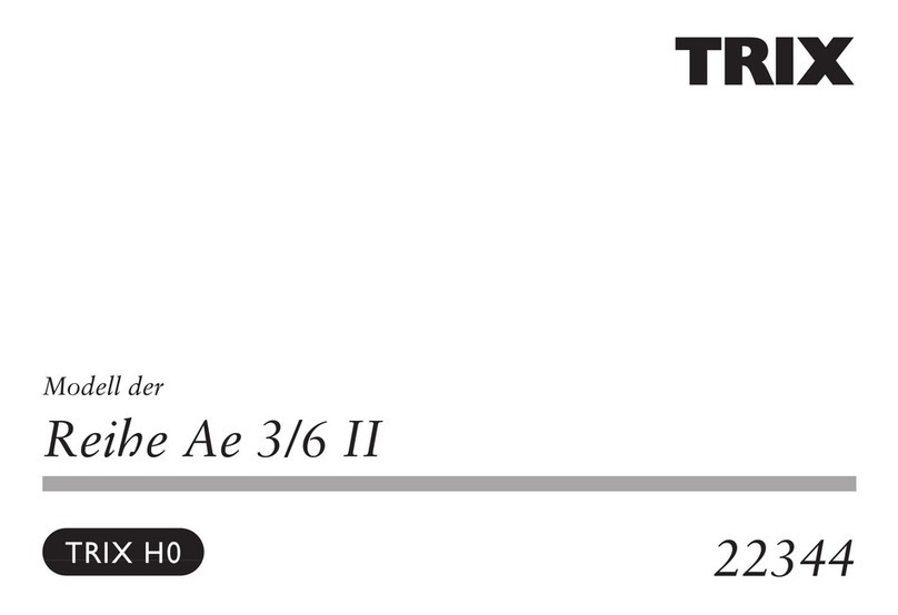
Trix Ce 6/8III Series User manual

Modell der Serie Ce 6/8III
22777

2
Inhaltsverzeichnis:
Seite
Informationen zum Vorbild 4
Sicherheitshinweise 6
Allgemeine Hinweise 6
Funktionen 6
Hinweise zum Digitalbetrieb 6
Schaltbare Funktionen 7
Parameter/Register 8
Betriebshinweise 30
Wartung und Instandhaltung 31
Ersatzteile 38
Table of Contents:
Page
Information about the prototype 4
Safety Notes 9
General Notes 9
Functions 9
Notes on digital operation 9
Controllable Functions 10
Parameter/Register 11
Information about operation 30
Service and maintenance 31
Spare Parts 38
Sommaire :
Page
Informations concernant la locomotive réelle 5
Remarques importantes sur la sécurité 12
Informations générales 12
Fonctionnement 12
Remarques relatives au fonctionnement en mode digital 12
Fonctions commutables 13
Paramètre/Registre 14
Remarques sur l’exploitation 30
Entretien et maintien 31
Pièces de rechange 38
Inhoudsopgave:
Pagina
Informatie van het voorbeeld 5
Veiligheidsvoorschriften 15
Algemene informatie 15
Functies 15
Aanwijzingen voor digitale besturing 15
Schakelbare functies 16
Parameter/Register 17
Opmerkingen over de werking 30
Onderhoud en handhaving 31
Onderdelen 38

3
Indice de contenido:
Página
Aviso de seguridad 18
Informaciones generales 18
Funciones 18
Informaciones para el funcionamiento digital 18
Funciones posibles 19
Parámetro/Registro 20
Instrucciones de uso 30
El mantenimiento 31
Recambios 38
Indice del contenuto:
Pagina
Avvertenze per la sicurezza 21
Avvertenze generali 21
Funzioni 21
Istruzioni per la funzione digitale 21
Funzioni commutabili 22
Parametro/Registro 23
Avvertenze per il funzionamento 30
Manutenzione ed assistere 31
Pezzi di ricambio 38
Innehållsförteckning:
Sida
Säkerhetsanvisningar 24
Allmänna informationer 24
Funktioner 24
Anvisningar för digital drift 24
Kopplingsbara funktioner 25
Parameter/Register 26
Driftanvisningar 30
Underhåll och reparation 31
Reservdelar 38
Indholdsfortegnelse:
Side
Vink om sikkerhed 27
Generelle oplysninger 27
Funktioner 27
Henvisninger til digitaldrift 27
Styrbare funktioner 28
Parameter/Register 29
Brugsanvisninger 30
Service og reparation 31
Reservedele 38

4
Informationen zum Vorbild:
Mit der Elektrifizierung der Gotthardbahn um 1920 ließen
die SBB neue schwere Gelenk-Lokomotiven für diese steile,
kurvenreiche Strecke entwickeln. Die charakteristische Form
dieser Maschinen mit den langen, flachen Vorbauten gab
ihnen den legendären Namen „Krokodil“.
Als Höhepunkt der Entwicklung wurde 1926 der Typ Ce 6/8III
in Dienst gestellt. Mit vier Motoren und 1.810 kW Leistung
sowie dem Schrägstangenantrieb wurden die braun la-
ckierten Lokomotiven für eine Geschwindigkeit von 65 km/h
zugelassen.
1953 wurde nach Umbau des Motors die zulässige Höchstge-
schwindigkeit auf 75 km/h erhöht und damit die Bezeichnung
der „Krokodile“ in Be 6/8III geändert. In den Vorjahren waren
die Maschinen bereits in der neueren grünen SBB-Farbge-
bung umlackiert worden.
Information about the Prototype:
With the electrification of the Gotthard route around 1920, the
SBB developed new, heavy, articulated locomotives for this
steep, winding rail line. The legendary name for these locomo-
tives, “Crocodile”, came from their long, flat ends.
The final development of these machines was the Ce 6/8III,
placed into service in 1926. These locomotives were painted
brown, had 4 motors producing 1,810 kw of power through a
jackshaft and drive rod system and had a maximum speed of
65 km/h (41 m.p.h.).
In 1953 the maximum speed was raised to 75 km/h (47 m.p.h.)
after the motors were rebuilt, and the “Crocodile’s” designa-
tion was changed to Be 6/8III. These locomotives had already
been painted in the newer SBB green paint scheme prior to
this time.

5
Informations concernant la locomotive réelle:
Avec l’électrification de la ligne sinueuse et à fortes pentes
du St. Gotthard vers 1920, les SBB ont dû mettre au point de
nouvelles motrices lourdes et articulées. Ces motrices ty-
piques, caractérisées par leurs longs capots plats, reçurent
le nom légendaire de «Crocodile».
C’est en 1926 que fut mis en service le type Ce 6/8III; aboutis-
sement des études. Il comporte 4 moteurs qui développent
une puissance de 1810 kW et dont la transmission est as-
surée par des bielles obliques. Ces motrices brunes étaient
limitées à 65 km/h.
En 1953, après modernisation des moteurs, la vitesse maxima
fut portée à 75 km/h et leur nouvelle numérotation devint
Be 6/8III. Signalons qu’avant cette renumérotation, les «Cro-
codiles» avaient une livrée verte, la nouvelle couleur SBB.
Informatie van het voorbeeld:
Met de electrificatie van de Gotthard-lijn rond 1920 lieten de
SBB nieuwe zware gelede locomotieven voor dit steile en
bochtige traject ontwikkelen. De karakteristieke vorm van
deze machines met hun lange en lage neuzen bezorgde hen
de legendarische naam “Krokodil”.
Als hoogtepunt bij de ontwikkeling werd in 1926 het
type Ce 6/8III in dienst gesteld. Met vier motoren en een
vermogen van 1810 kW alsmede de schuingeplaatste
stangenaandrijving werden de bruingelakte locomotie-
ven toegelaten voor een snelheid tot 65 km/h.
Na ombouw van de motor werd in 1953 de toelaatbare max.
snelheid tot 75 km/h verhoogd en werd de type-aanduiding
van de “Krokodillen” in Be 6/8III veranderd. Voordien ware
de machines reeds in de nieuwe groene SBB-kleurstelling
omgeschilderd.

6
Sicherheitshinweise
• DieLokdarfnurmiteinemdafürbestimmtenBetriebssys-
tem eingesetzt werden.
• NurSchaltnetzteileundTransformatorenverwenden,die
Ihrer örtlichen Netzspannung entsprechen.
• DieLokdarfnurausalseinerLeistungsquelleversorgt
werden.
• BeachtenSieunbedingtdieSicherheitshinweiseinder
Bedienungsanleitung zu Ihrem Betriebssystem.
• FürdenkonventionellenBetriebderLokmussdasAn-
schlussgleis entstört werden. Dazu ist das Entstörset
611 655 zu verwenden. Für Digitalbetrieb ist das Entstör-
set nicht geeignet.
• ACHTUNG! Funktionsbedingte scharfe Kanten und Spitzen.
• SetzenSiedasModellkeinerdirektenSonneneinstrah-
lung, starken Temperaturschwankungen oder hoher
Luftfeuchtigkeit aus.
Allgemeine Hinweise
• DieBedienungsanleitungunddieVerpackungsind
Bestandteil des Produktes und müssen deshalb aufbe-
wahrt sowie bei Weitergabe des Produktes mitgegeben
werden.
• FürReparaturenoderErsatzteilewendenSiesichbittean
Ihren Trix-Fachhändler.
• http://www.maerklin.com/en/imprint.html
Funktionen
• EingebauteElektronikzumwahlweisenBetriebmit
konventionellem Gleichstrom-Fahrgerät (max. ±12 Volt),
Trix Systems oder Digitalsystemen nach NMRA-Norm.
• AutomatischeSystemerkennungzwischenDigital-und
Analog-Betrieb.
• DervolleFunktionsumfangistnurunterTrixSystemsund
unter DCC verfügbar.
• Eingebaute,fahrtrichtungsabhängigeStirnbeleuchtung.
Im Digitalbetrieb schaltbar.
• BefahrbarerMindestradius360mm.
Hinweise zum Digitalbetrieb
• DiegenaueVorgehensweisezumEinstellenderdiversen
Parameter entnehmen Sie bitte der Bedienungsanleitung
Ihrer Mehrzug-Zentrale.
• DieabWerkeingestelltenWertesindsogewählt,dass
bestmöglichstes Fahrverhalten gewährleistet ist.
• DerBetriebmitgegenpoligerGleichspannungim
Bremsabschnitt ist mit der werkseitigen Einstellung
nicht möglich. Ist diese Eigenschaft gewünscht, so muss
auf den konventionellen Gleichstrombetrieb verzichtet
werden (CV 29/Bit 2 = 0).
Jegliche Garantie-, Gewährleistungs- und Schadensersatzansprüche sind ausge-
schlossen, wenn in Trix-Produkten nicht von Trix freigegebene Fremdteile eingebaut
werden und/oder Trix-Produkte umgebaut werden und die eingebauten Fremdteile
bzw. der Umbau für sodann aufgetretene Mängel und/oder Schäden ursächlich war.
Die Darlegungs- und Beweislast dafür, dass der Einbau von Fremdteilen oder der
Umbau in bzw. von Trix-Produkten für aufgetretene Mängel und/oder Schäden nicht
ursächlich war, trägt die für den Ein- und/oder Umbau verantwortliche Person und/
oder Firma bzw. der Kunde.

7
Schaltbare Funktionen
Spitzensignal an Funktion f0 Funktion f0
Schlusslicht rot — Funktion 1 Funktion f1 Funktion f1
Geräusch:Betriebsgeräusch — Funktion 2 Funktion f2 Funktion f2
Geräusch:Lokpfeifelang — Funktion 3 Funktion f3 Funktion f3
ABV — Funktion 4 Funktion f4 Funktion f4
Geräusch:Bremsenquietschenaus — Funktion 5 Funktion f5 Funktion f5
Geräusch:Bahnhofsansage — Funktion 6 Funktion f6 Funktion f6
Geräusch:Lokpfeifekurz — Funktion 7 Funktion f7 Funktion f7
Geräusch:Lüfter — Funktion 8 Funktion f8 Funktion f8
Geräusch:Ankuppeln(PufferanPuffer) — — Funktion f9 Funktion f9
Geräusch:Pressluft — — Funktion f10 Funktion f10
Geräusch:Luftpresser — — Funktion f11 Funktion f11
Geräusch:Pantograph — — Funktion f12 Funktion f12
STOP mobile station
15
f0 f8 f0f8
f0 - f3 f4 - f7

8
CV Bedeutung Wert DCC ab Werk
1 Adresse 1 - 127 3
2 PoM Minimalgeschwindigkeit 0 - 255 7
3 PoM Anfahrverzögerung 0 - 255 6
4 PoM Bremsverzögerung 0 - 255 4
5 PoM Maximalgeschwindigkeit 0 - 255 210
8 Werkreset/Herstellerkennung 8 131
13 PoM Funktionen F1 - F8 im Analogbetrieb 0 - 255 0
14 PoM Funktionen F9 - F15 und Licht im Analogbetrieb 0 - 255 1
17 Erweiterte Adresse (oberer Teil) CV 29, Bit 5 =1 192
18 Erweiterte Adresse (unterer Teil) CV 29, Bit 5 =1 128
19 Traktionsadresse 0 - 255 0
21 PoM Funktionen F1 - F8 bei Traktion 0 - 255 0
22 PoM Funktionen F9 - F15 und Licht bei Traktion 0 - 255 0
29 PoM
Bit0:UmpolungFahrtrichtung
Bit1:AnzahlFahrstufen14oder28/128
Bit2:DCCBetriebmitBremsstrecke(keinAnalogbetriebmöglich)
Bit5:Adressumfang7Bit/14Bit
0/1
0/2
0/4
0/32
6*
63 PoM Lautstärke 0 - 255 255
PoM = Program on the Main; muss vom Steuergerät unterstützt werden.
* Die Werte der gewünschten Einstellungen sind zu addieren!

9
Functions
• Built-inelectroniccircuitforoperationwithaconven-
tional DC power pack (max. ±12 volts), Trix Systems or
NMRA DCC digital systems.
• Automaticsystemrecognitionbetweendigitalandanalog
operation.
• ThefullrangeoffunctionsisonlyavailableunderTrix
Systems and under DCC.
• Built-inheadlightsthatchangeoverwiththedirectionof
travel. They can be turned on and off in digital operation.
• Minimumradiusforoperationis360mm/14-3/16“.
Notes on digital operation
• Theoperatinginstructionsforyourcentralunitwillgive
you exact procedures for setting the different parame-
ters.
• Thevaluessetatthefactorywereselectedtoguarantee
the best possible running characteristics.
• Thesettingdoneatthefactorydoesnotpermitoperation
with opposite polarity DC power in the braking block.
If you want this characteristic, you must do without
conventional DC power operation (CV 29/Bit 2 = 0).
No warranty or damage claims shall be accepted in those cases where parts
neither manufactured nor approved by Trix have been installed in Trix products or
where Trix products have been converted in such a way that the non-Trix parts or
the conversion were causal to the defects and/or damage arising. The burden of
presenting evidence and the burden of proof thereof, that the installation of non-Trix
parts or the conversion in or of Trix products was not causal to the defects and/
or damage arising, is borne by the person and/or company responsible for the
installation and/or conversion, or by the customer.
Safety Notes
• Thislocomotiveisonlytobeusedwiththeoperating
system it is designed for.
• Useonlyswitchedmodepowersupplyunitsandtransfor-
mers that are designed for your local power system.
• Thislocomotivemustnotbesuppliedwithpowernever
from more than one power source.
• Pleasemakenoteofthesafetynotesintheinstructions
for your operating system.
• Thefeedertrackmustbeequippedtopreventinter-
ference with radio and television reception, when the
locomotive is to be run in conventional operation. The
611 655 interference suppression set is to be used for this
purpose. The interference suppression set is not suitable
for digital operation.
• WARNING! Sharp edges and points required for operation.
• Donotexposethemodeltodirectsunlight,extreme
changes in temperature, or high humidity.
General Notes
• Theoperatinginstructionsandthepackagingareacom-
ponent part of the product and must therefore be kept as
well as transferred along with the product to others.
• PleaseseeyourauthorizedTrixdealerforrepairsor
spare parts.
• http://www.maerklin.com/en/imprint.html
10
Controllable Functions
Headlights/marker lights on Function f0 Function f0
Red marker light — Function 1 Function f1 Function f1
Soundeffect:Operatingsounds — Function 2 Function f2 Function f2
Soundeffect:longwhistleblast — Function 3 Function f3 Function f3
ABV — Function 4 Function f4 Function f4
Soundeffect:Squealingbrakesoff — Function 5 Function f5 Function f5
Soundeffect:Stationannouncements — Function 6 Function f6 Function f6
Soundeffect:Shortwhistleblast — Function 7 Function f7 Function f7
Soundeffect:Blower — Function 8 Function f8 Function f8
Soundeffect:couplingtogether(buffertobuffer) — — Function f9 Function f9
Soundeffect:compressedair — — Function f10 Function f10
Soundeffect:compressor — — Function f11 Function f11
Soundeffect:pantograph — — Function f12 Function f12
STOP mobile station
15
f0 f8 f0f8
f0 - f3 f4 - f7

11
PoM = Program on the Main; must be supported by the controller.
* The values for the desired settings must be added.
CV Discription DCC Value Factory-Set
1 Adresse 1 - 127 3
2 PoM Minimum Speed 0 - 255 7
3 PoM Acceleration delay 0 - 255 6
4 PoM Braking delay 0 - 255 4
5 PoM Maximum speed 0 - 255 210
8 Factory Reset/Manufacturer Recognition 8 131
13 PoM Functions F1 - F8 in analog operation 0 - 255 0
14 PoM Functions F9 - F15 and lights in analog operation 0 - 255 1
17 Extended address (upper part) CV 29, Bit 5 =1 192
18 Extended address (lower part) CV 29, Bit 5 =1 128
19 Multiple Unit Address 0 - 255 0
21 PoM Functions F1 - F8 on Multiple Unit 0 - 255 0
22 PoM Functions F9 - F15 and lights on Multiple Unit 0 - 255 0
29 PoM
Bit0:Reversingdirection
Bit1:Numberofspeedlevels14or28/128
Bit2:DCCoperationwithbrakingarea(noanalogoperationpossible)
Bit5:Addresslength7Bit/14Bit
0/1
0/2
0/4
0/32
6*
63 PoM Volume 0 - 255 255

12
Remarques importantes sur la sécurité
• Lalocomotivenepeutêtreutiliséequ‘aveclesystème
d‘exploitationindiqué.
• Utiliseruniquementdesconvertisseursettransforma-
teurs correspondant à la tension du secteur local.
• Lalocomotivenepeutpasêtrealimentéeélectriquement
parplusd‘unesourcedecourantàlafois.
• Ilestimpératifdetenircomptedesremarquessurla
sécuritédécritesdanslemoded‘emploidevotresystème
d‘exploitation.
•
Pour l’exploitation de la locomotive en mode conventi-
onnel,lavoiederaccordementdoitêtredéparasitée.A
cet effet, utiliser le set de déparasitage réf. 611 655. Le set
de déparasitage ne convient pas pour l’exploitation en
mode numérique.
•
ATTENTION! Pointes et bords coupants lors du fonctionne-
ment du produit.
• Nepasexposerlemodèleàunensoleillementdirect,
à de fortes variations de température ou à un taux
d‘humiditéimportant.
Informations générales
• Lanoticed‘utilisationetl’emballagefontpartieintégrante
duproduit;ilsdoiventdoncêtreconservéset,lecas
échéant, transmis avec le produit.
• Pourtouteréparationouremplacementdepièces,
adressez vous à votre détaillant-spécialiste Trix.
• http://www.maerklin.com/en/imprint.html
Fonctionnement
• Electroniqueintégréepourexploitationauchoixavec
transformateur-régulateur conventionnel délivrant du
courant continu (max. ±12 volts), avec Trix Systems ou avec
des systèmes de conduite digitale conformes aux normes
NMRA.
• Reconnaissanceautomatiquedusystèmeentreexploita-
tions numérique et analogique.
• L’intégralitédesfonctionsestdisponibleuniquementen
exploitation Trix Systems et DCC.
• Feuxdesignalisations‘inversantselonlesensdemar-
che; feux commutables en exploitation digital.
• Rayonminimald’inscriptionencourbe360mm.
Remarques relatives au fonctionnement en mode digital
• Encequiconcernelaprocédurederéglagedesdivers
paramètres,veuillezvousréféreraumoded‘emploide
votre centrale de commande multitrain.
• Lesvaleursparamétréesd’usinesontchoisiesdemanière
à garantir le meilleur comportement de roulement possible.
• L’exploitationaveccourantcontinudepolaritéinverse
dans les sections de freinage n’est pas possible avec
le réglage d’usine. Si cette propriété est désirée, il faut
alors renoncer à l’exploitation conventionnelle en cou-
rant continu (CV 29/Bit 2 = 0).
Tout recours à une garantie commerciale ou contractuelle ou à une demande de
dommages-intérêtestexclusidespiècesnonautoriséesparTrixsontintégréesdans
les produits Trix et/ou si les produits Trix sont transformés et si les pièces d’autres
fabricants montées ou la transformation constituent la cause des défauts et/ou
dommages apparus. C’est à la personne et/ou la société responsable du montage/de
la transformation ou au client qu’incombe la charge de prouver que le montage des
pièces d’autres fabricants sur des produits Trix ou la transformation des produits Trix
n’est pas à l’origine des défauts et ou dommages apparus.

13
Fonctions commutables
Fanal éclairage Activé Fonction f0 Fonction f0
Feu de fin de convoi rouge — Fonction 1 Fonction f1 Fonction f1
Bruitage:bruitd’exploitation — Fonction 2 Fonction f2 Fonction f2
Bruitage:sifetlongueur — Fonction 3 Fonction f3 Fonction f3
ABV — Fonction 4 Fonction f4 Fonction f4
Bruitage:grincementdefreinsdésactivé — Fonction 5 Fonction f5 Fonction f5
Bruitage:annonceengare — Fonction 6 Fonction f6 Fonction f6
Bruitage:sifetcourt — Fonction 7 Fonction f7 Fonction f7
Bruitage:ventilateur — Fonction 8 Fonction f8 Fonction f8
Bruitage:attelage(tamponsjoints) — — Fonction f9 Fonction f9
Bruitage:aircomprimé — — Fonction f10 Fonction f10
Bruitage:compresseur — — Fonction f11 Fonction f11
Bruitage:pantographe — — Fonction f12 Fonction f12
STOP mobile station
15
f0 f8 f0f8
f0 - f3 f4 - f7

14
PoM=ProgramontheMain;doitêtreprisenchargeparl’appareildecommande.
* Les valeurs des réglages désirés sont à additioner.
CV Affectation DCC Valeur Parm. Usine
1 Adresse 1 - 127 3
2 PoM Vitesse minimale 0 - 255 7
3 PoM Temporisationd‘accélération 0 - 255 6
4 PoM Temporisation de freinage 0 - 255 4
5 PoM Vitesse maximale 0 - 255 210
8 Réinitialisation d’usine/identification du fabricant 8 131
13 PoM Fonctions F1 - F8 en mode analog 0 - 255 0
14 PoM Fonctions F9 - F15 et éclairage en mode analog 0 - 255 1
17 Adresse étendue (partie supérieure) CV 29, Bit 5 =1 192
18 Adresse étendue (partie inférieure) CV 29, Bit 5 =1 128
19 Adresse traction 0 - 255 0
21 PoM Fonctions F1 - F8 pour traction 0 - 255 0
22 PoM Fonctions F9 - F15 et éclairage traction 0 - 255 0
29 PoM
Bit0:Inv.polaritéSensdemarche
Bit1:Nombredecransdemarche14ou28/128
Bit2:
Mode DCC avec dist. de freinage (mode analog impossible)
Bit5:Capacitéd’adresses7Bit/14Bit
0/1
0/2
0/4
0/32
6*
63 PoM Volume haut-parleur 0 - 255 255

15
Veiligheidsvoorschriften
• Delocmagalleenmeteendaarvoorbestemdbedrijfssys-
teem gebruikt worden.
• Alleennet-adaptersentransformatorengebruiken
waarvan de aangegeven netspanning overeenkomt met de
netspanning ter plaatse.
• Delocmagnietvanuitmeerdanéénstroomvoorziening
gelijktijdig gevoed worden.
• Leesookaandachtigdeveiligheidsvoorschrifteninde
gebruiksaanwijzing van uw bedrijfssysteem.
• Voorhetconventionelebedrijfmetdelocdientde
aansluitrail te worden ontstoort. Hiervoor dient men de
ontstoor-set 611 655 te gebruiken. Voor het digitale bedrijf
is deze ontstoor-set niet geschikt.
• OPGEPAST! Functionele scherpe kanten en punten.
• Stelhetmodelnietblootaanindirectezonnestraling,
sterke temperatuurwisselingen of hoge luchtvochtigheid.
Algemene informatie
• Degebruiksaanwijzingendeverpakkingzijneenbe-
standdeel van het product en dienen derhalve bewaard
en meegeleverd te worden bij het doorgeven van het
product.
• VoorreparatiesenonderdelenkuntzichtotUwTrix
handelaar wenden.
• http://www.maerklin.com/en/imprint.html
Functies
• Ingebouwdeelektronicadiehetmogelijkmaaktomnaar
keuze met, een conventionele gelijkstroomrijregelaar
(max. ±12 Volt), Trix Systems of digitaalsysteem volgens
NMRA-norm te rijden.
• Automatischesysteemherkenningtussendigitaal-en
analoogbedrijf.
• Devolledigetoegangtotallefunctiesisalleenmogelijk
met Trix Systems of met DCC bedrijf.
• Ingebouwde,rijrichtingsafhankelijkefrontverlichting.
• Minimaleteberijdenradius:360mm.
Aanwijzingen voor digitale besturing
• Hetopdejuistewijzeinstellenvandediverseparame-
ters staat beschreven in de handleiding van uw digitale
Centrale.
• Devanafdefabriekingesteldewaardenzijnzoingesteld
dat de rij-eigenschappen optimaal zijn.
• Hetbedrijfmettegengepooldegelijkspanningindeafrem-
sectie is met de fabrieksinstelling niet mogelijk. Indien deze
eigenschap wenselijk is, dan moet worden afgezien van
het conventioneel gelijkstroombedrijf (CV 29/Bit 2 = 0).
Elke aanspraak op garantie en schadevergoeding is uitgesloten, wanneer in
Trix-producten niet door Trix vrijgegeven vreemde onderdelen ingebouwd en/
of Trix-producten omgebouwd worden en de ingebouwde vreemde onderdelen
resp. de ombouw oorzaak van nadien opgetreden defecten en/of schade was. De
aantoonplicht en de bewijslijst daaromtrent, dat de inbouw van vreemde onderdelen
in Trix-producten of de ombouw van Trix-producten niet de oorzaak van opgetreden
defecten en/of schade is geweest, berust bij de voor de inbouw en/of ombouw
verantwoordelijke persoon en/of firma danwel bij de klant.

16
Schakelbare functies
Frontsein aan Functie f0 Functie f0
Sluitlicht rood — Functie 1 Functie f1 Functie f1
Geluid:bedrijfsgeluiden — Functie 2 Functie f2 Functie f2
Geluid:uitlang — Functie 3 Functie f3 Functie f3
ABV — Functie 4 Functie f4 Functie f4
Geluid:piependeremmenuit — Functie 5 Functie f5 Functie f5
Geluid:stationsomroep — Functie 6 Functie f6 Functie f6
Geluid:uitkort — Functie 7 Functie f7 Functie f7
Geluid:ventilator — Functie 8 Functie f8 Functie f8
Geluid:aankoppelen(bufferaanbuffer) — — Functie f9 Functie f9
Geluid:perslucht — — Functie f10 Functie f10
Geluid:compressor — — Functie f11 Functie f11
Geluid:pantograaf — — Functie f12 Functie f12
STOP mobile station
15
f0 f8 f0f8
f0 - f3 f4 - f7

17
PoM = Program on the Main; dient door het besturingsapparaat ondersteunt te worden.
* De waarde van de gewenste instellingen moeten bij elkaar opgeteld worden.
CV Betekenis Waarde DCC Af fabriek
1 Adres 1 - 127 3
2 PoM minimale snelheid 0 - 255 7
3 PoM Optrekvertraging 0 - 255 6
4 PoM Afremvertraging 0 - 255 4
5 PoM Maximumsnelheid 0 - 255 210
8 Fabrieksinstelling/fabriekherkenning 8 131
13 PoM functies F1 - F8 in analoogbedrijf 0 - 255 0
14 PoM functies F9 - F15 en licht in analoogbedrijf 0 - 255 1
17 Uitgebreld adres (bovenste gedeelte) CV 29, Bit 5 =1 192
18 Uitgebreld adres (onderste gedeelte) CV 29, Bit 5 =1 128
19 tractieadres 0 - 255 0
21 PoM functies F1 - F8 in tractie 0 - 255 0
22 PoM functies F9 - F15 en licht in tractie 0 - 255 0
29 PoM
Bit0:ompolenrijrichting
Bit1:aantalrijstappen14of28/128
Bit2:DCCbedrijfmetafremtraject(geenanaloogbedrijfmogelijk)
Bit5:adresomvang7Bit/14Bit
0/1
0/2
0/4
0/32
6*
63 PoM Volume 0 - 255 255

18
Aviso de seguridad
• Lalocomotorasolamentedebefuncionarenelsistema
que le corresponda.
• Emplearúnicamentefuentesdealimentaciónconmu-
tadasytransformadoresqueseandelatensióndered
local.
• Lalocomotoranodeberárecibircorrientemásquedeun
solo punto de abasto a la vez.
• Observenecesariamentelosavisosdeseguridadindica-
dos en las instrucciones correspondientes a su sistema
de funcionamiento.
• Paraelfuncionamientoconvencionaldelalocomotora
debensuprimirselasinterferenciasenlavíadeconexión
delaalimentación.Paraellodebeemplearseelset
supresor de interferencias 611 655.
• ¡ATENCIÓN! Esquinas y puntas afiladas condicionadas a
lafunción.
• Noexponerelmodeloenminiaturaalaradiaciónsolar
directa, a oscilaciones fuertes de temperatura o a una
humedad del aire elevada.
Informaciones generales
• Lasinstruccionesdeempleoyelembalajeformanparte
íntegra del producto y, por este motivo, deben guardarse
y entregarse junto con el producto en el caso de venderlo
o transmitirlo a otro.
•
Encasodeprecisarunareparaciónopiezasderecambio,
rogamos ponerse en contacto con su distribuidor Trix.
• http://www.maerklin.com/en/imprint.html
Funciones
• Electrónicaincorporadaparaunfuncionamientoadiscre-
ciónencorrientecontinuaconvencional(máx.±12V.),Trix
SystemsosistemasDigitalsegúnlasnormasNMRA.
• Detecciónautomáticadelsistemaentrelosmodosdigital
yanalógico.
• Laplenafuncionalidaddefuncionesestádisponiblesólo
en Trix Systems y en DCC.
• Losfarosfrontalesdependendelsentidodelamarcha.
En Digital se pueden encender y apagar.
• Radiomínimodescribible360mm.
Informaciones para el funcionamiento digital
• Deberáconsultarelprocedimientoexactodecon-
guracióndelosdiversosparámetrosenelmanualde
instrucciones de la central multitren que desee utilizar.
• Losvaloresconguradosenfábricasehanelegidode
modo que queden garantizadas las mejores característi-
casdeconducciónposibles.
• Noesposibleelfuncionamientocontensióndecorriente
continua de polaridad opuesta en el tramo de frenado en
funcionamiento en modo DCC. Si se desea esta caracterí-
stica, debe renunciarse al funcionamiento convencional
con corriente continua (CV 29/Bit 2 = 0).
Seexcluyetododerechodegarantía,prestacióndegarantíaeindemnizaciónsobre
aquellos productos Trix en los que se hubieran montado piezas ajenas no autorizadas
por Trix y/o sobre aquellos productos Trix que hayan sido modificados cuando la piezas
ajenasmontadasolamodicaciónseanlascausasdelosdesperfectosy/odaños
posteriormente surgidos. La persona y/o empresa o el cliente responsable del montaje
omodicaciónseráelresponsabledeprobaryalegarqueelmontajedepiezasajenas
olamodicaciónen/deproductosTrixnosonlascausasdelosdesperfectosy/odaños
surgidos.

19
Funciones posibles
Faros frontales encendido Funciónf0 Funciónf0
Luces de cola rojas — Función1 Funciónf1 Funciónf1
Ruido:Ruidodeexplotación —Función2 Funciónf2 Funciónf2
Ruido del silbido larga — Función3 Funciónf3 Funciónf3
ABV — Función4 Funciónf4 Funciónf4
Ruido:Desconectarchirridodelosfrenos —Función5 Funciónf5 Funciónf5
Ruido:Locuciónhabladaenestaciones —Función6 Funciónf6 Funciónf6
Ruido del silbido corta —Función7 Funciónf7 Funciónf7
Ruido:Ventilador —Función8 Funciónf8 Funciónf8
Ruido:Enganchedecoches/vagones(topecontratope) — — Funciónf9 Funciónf9
Ruido:Airecomprimido — — Funciónf10 Funciónf10
Ruido:Compresor — — Funciónf11 Funciónf11
Ruido:Pantógrafo — — Funciónf12 Funciónf12
STOP mobile station
15
f0 f8 f0f8
f0 - f3 f4 - f7

20
PoM = Program on the Main; debe ser soportado por la unidad de control.
* ¡Los valores de los ajustes deseados deben sumarse!
CV Significado Valor DCC Preselec-
ción
1Códigos 1 - 127 3
2 PoM Velocidad mínima 0 - 255 7
3 PoM Arranque progresivo 0 - 255 6
4 PoM Frenado progresivo 0 - 255 4
5 PoM Velocidad máxima 0 - 255 210
8Resetdefábrica/códigodefabricante 8 131
13 PoM FuncionesF1-F8enelmodoanalógico 0 - 255 0
14 PoM FuncionesF9-F15ylucesenelmodoanalógico 0 - 255 1
17 Direcciónampliada(partesuperior) CV 29, Bit 5 =1 192
18 Direcciónampliada(parteinferior) CV 29, Bit 5 =1 128
19 Direccióndetracción 0 - 255 0
21 PoM FuncionesF1-F8entracción 0 - 255 0
22 PoM FuncionesF9-F15ylucesentracción 0 - 255 0
29 PoM
Bit0:Cambiodepolaridaddelsentidodemarcha
Bit1:Númerodenivelesdemarcha14ó28/128
Bit2:ModoDCCcontrayectodefrenado(noesposibleelmodoanalógico)
Bit5:Tamañodedirecciones7Bits/14Bits
0/1
0/2
0/4
0/32
6*
63 PoM Volumen del sonido 0 - 255 255
Other manuals for Ce 6/8III Series
2
Table of contents
Languages:
Other Trix Toy manuals

Trix
Trix Minitrix BR 218 217 User manual

Trix
Trix Minitrix BR 44 User manual

Trix
Trix PA-1 User manual

Trix
Trix BR 103 / E 03 User manual

Trix
Trix 62997 User manual

Trix
Trix 1012 Series User manual

Trix
Trix Ce 6/8 II Series User manual

Trix
Trix H0 BR 05 User manual

Trix
Trix BR 103 User manual

Trix
Trix Elektrolok Baureihe TRAXX 2 E 186 22165 User manual

Trix
Trix E 50/BR 150 22155 User manual

Trix
Trix 22373 User manual

Trix
Trix 21518 User manual

Trix
Trix BR 44 Marklineum User manual

Trix
Trix Minitrix BR 232 User manual

Trix
Trix 150Z Series User manual

Trix
Trix BR 260 User manual

Trix
Trix 16083 User manual

Trix
Trix 22599 User manual

Trix
Trix 11205 User manual