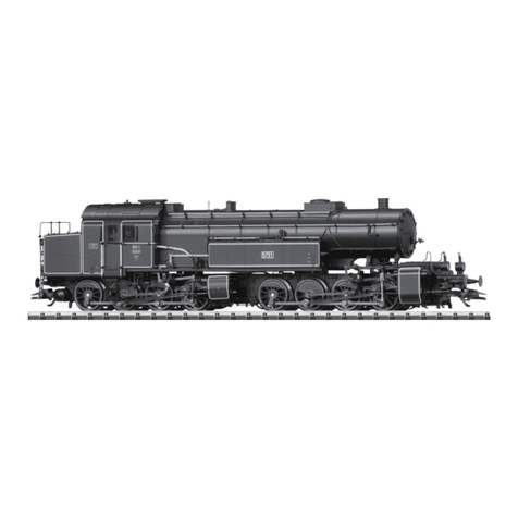
Trix Gt 2 x 4/4 Series User manual

Modell der
Baureihe Gt 2 x 4/4 (BR 96)

Information about the PrototypeInformation zum Vorbild
2
Auf drei Steilrampen im Bereich der Bayerischen Staats-
bahn waren Anfang dieses Jahrhunderts die eingesetzten
Lokomotiven den Anforderungen bezüglich der erforder-
lichen Zugleistung nicht mehr gewachsen. Daher bekam
die Firma Maffei den Auftrag, eine leistungsfähige Tender-
lok für diese Strecken zu konstruieren und zu bauen.
Das Ergebnis war die Tenderlokomotive mit der Gattungs-
bezeichnung Gt 2 x 4/4. Mit einer Länge über Puffer von
17 700 mm und einer Leistung von 1080 kW (1470 PS)
war diese Lok damals die größte und leistungsfähigste
Tenderlok Europas.
Damit die Vorgaben bezüglich maximaler Achslast von 15
t bei gleichzeitigem großen Kessel eingehalten werden
konnten entschied man sich bei Maffei für ein Triebwerk
der Bauart Mallet, wodurch trotz der großen Länge der
Lok eine gute Kurventauglichkeit gesichert war.
Die erste Lokbauserie wurde ab 1913 ausgeliefert.
Ab 1922 wurde eine zweite Bauserie mit einer noch hö-
heren Leistung ausgeliefert. Alle Lokomotiven wurden als
BR 96 im Güter- und Personenverkehr eingesetzt. Einige
Lokomotiven waren auch nach 1945 noch in Bayern im
Einsatz.
At the start of this century the locomotives in use on
three steeply graded routes in the area administered by
the Bavarian State Railroad could no longer meet the re-
quirements for powering trains over the routes. The Maffei
Company was therefore given an orderto design and build
a powerful tank locomotive for these routes.
The result was the tank locomotive with the designation
Gt 2 x 4/4. With a langth of 17,700 mm (approx. 58 feet)
and an output of 1,080 kilowatts (1,470 horsepower)
this locomotive was the largest and most powerful tank
locomotive in Europe at the time.
In order to keep the maximum axle load to 15 tons while
maintaining a large boiler as part of the design, it was
decided at Maffei to build a Mallet type of frame which
insured that the locomotive could negotiate sharp curves
despite its great length.
The first series was delivered in 1913. Starting in 1922 a
second series with a still high power output was deliver-
ed. All of these locomotives were taken over by the DRG
and were used as the class 96 in freight and passenger
traffic. A few units were still in use in Bavaria even after
1945.

Informations concernant la locomotive réele Informatie van het voorbeeld
3
Les locomotives utilisées au début de ce siècle sur trois
côtes du réseau de Chemins de fer nationaux bavarois
n’étaient plus à même de satisfaire aux exigences en
matière de puissance de traction requises. C’est la raison
pour laquelle la sociêté Maffei fut chargée de développer
et de construire une locomotive tender puissante pour
ces lignes.
Le résultat en fut la locomotive tender connue sous la dé-
signation Gt 2 x 4’4. Avec une longueur hors tampons de
17 700 mm et une puissance de 1080 kW (1 470 PS) cette
locomotive était alors la plus grande et la plus puissante
locomotive tender d’Europe.
Afin de repecter les instructions concernant la charge
maximale par essieu de 15 t, et ce malgré la grande
chaudière, les ingénieurs de Maffei optèrent pour un
mécanisme de locomotion de type Benart Mallet, qui
permettait d’assurer une bonne tenue en courbe, malgré
la grande longueur de la locomotive.
La première série de locomotives fut livrée à partir de
1913. Une deuxième série encore plus puissante fut livrée
à partir de 1922. Toutes les locomotives furent reprises
par la DRG et furent utilisées dans le trafic de voyageurs
et dans le trafic de archandises sous l’apellation BR
96. Quelques locomotives étaient encore en service en
Bavière près 1945.
Op drie steile trajecten binnen het gebied van de Baye-
rische Staatsbahn waren in het begin van deze eeuw de
ingezette locomotieven niet langer opgewassen tegen de
gestelde eisen wat betreft de treinvermogens. Daarom
kreeg de firma Maffei de opdracht een sterke tenderlok
voor deze trajecten de ontwikkelen en te bouwen.
Het resultaat was de tenderlokomotief met de soortaan-
duiding Gt 2 x 4/4. Met een lengte over buffers van 17
700 mm en een vermogen van
1080 kW (1 470 pk) was deze lok toentertijd de grootste
en sterkste tenderlok in Europa.
Om binnen de gestelde maten voor de asdruk
(15 ton) en toch met een grote ketel te kunnen
blijven, besloot men bij Maffei tot een drijfwerk volgens
het systeem van Mallet, waardoor ondanks de grote
lengte van de lok toch een goede loop in bogen verzekerd
was.
De eerste lokserie werd vanaf 1913 afgeleverd. Vanaf
1922 werd een tweede serie met een groter vermogen
afgeleverd. Alle lokomotieven werden door de DRG over-
genomen en ze werden als serie 96 in het goederen- en
personenvervoer ingezt. Enkele lokomotieven waren ook
na 1945 nog in gebruik in Beieren.

4
Funktion
22013, 22017:
• Das Modell ist für den Betrieb auf H0-Zweileiter-
Gleichstrom-Systemen (Gleisen nach NEM) mit herkömm-
lichen Gleichstrom-Fahrpulten (12 V) vorgesehen.
• Diese Lokomotive ist mit einer Trix- Schnittstelle für
Digitalbetrieb ausgestattet und kann mit dem Trix-Fahr-
zeug-Decoder 66839 nachgerüstet werden.
• Fahrtrichtungs- und fahrspannungsabhängige Stirnbe-
leuchtung.
22012, 22016:
• Mögliche Betriebssysteme: Gleichstrom nach NEM (±
12 Volt =), DCC System (nach NMRA-Norm).
• Selectrix-Betrieb: Central Control 2000 muss auf DCC-
Betrieb für diesen Zug umgeschaltet werden.
• Diverse schaltbare Licht- und Soundfunktionen im
Betrieb mit DCC.
• Fahrtrichtungs- und fahrspannungsabhängige Stirnbe-
leuchtung im Gleichstrom-Betrieb.
• Nur für den DCC-Betrieb: Einstellen verschiedener
Parameter (Adresse, Höchstgeschwindigkeit,
Anfahrverzögerung, Bremsverzögerung, Laut-
stärke). Eingestellte Adresse ab Werk: 03.
22012, 22013, 22016, 22017:
• Ein Betrieb mit Gleichstrom-Fahrgeräten ist nur bei
ausreichender Funkentstörung der Gleisanlage erlaubt.
Geeignete Funkentstörung für das Trix-C-Gleis: 611 655
Die bei normalem Betrieb anfallenden Wartungsarbeiten
sind nachfolgend beschrieben. Für Reparaturen oder Er-
satzteile wenden Sie sich bitte an Ihren Trix-Fachhändler.
Jegliche Garantie-, Gewährleistungs- und Schadensersatzansprü-
che sind ausgeschlossen, wenn in Trix-Produkten nicht von Trix
freigegebene Fremdteile eingebaut werden und / oder Trix-Produkte
umgebaut werden und die eingebauten Fremdteile bzw. der Umbau
für sodann aufgetretene Mängel und / oder Schäden ursächlich
war. Die Darlegungs- und Beweislast dafür, dass der Einbau von
Fremdteilen oder der Umbau in bzw. von Trix-Produkten für aufge-
tretene Mängel und/oder Schäden nicht ursächlich war, trägt die für
den Ein- und / oder Umbau verantwortliche Person und/ oder Firma
bzw. der Kunde.
Sicherheitshinweise
• Die Lok darf nur mit einem dafür bestimmten Betriebs-
system eingesetzt werden.
• Die Lok darf nicht mit mehr als einer Leistungsquelle
gleichzeitig versorgt werden.
• Beachten Sie unbedingt die Sicherheitshinweise in der
Gebrauchsanleitung zu Ihrem Betriebs-system.
• Trix Triebfahrzeuge dürfen auf Digitalanlagen nicht ohne
eingebauten Lokdecoder betrieben werden (Beschädi-
gung des Motors möglich!).

5
Function
22013, 22017:
• This model is designed for operation with H0 2-rail
DC systems (track according to NEM standards) with
conventional DC power packs (12 volts).
• This locomotive is equipped with an Trix interface con-
nection for digital operation and can be retrofitted with
the 66839 Trix locomotive decoder.
• Headlights change over with the direction of travel and
vary in brightness according to the voltage present in
the track.
22012, 22016:
• Possible operating systems: NEM direct current (± 12
volts DC), DCC System (NMRA standard).
• Selectrix operation: Central Control 2000 must be set
for DCC operation for this train.
• Different controllable light and sound functions when
the model is operated with DCC.
• Headlights change over with the direction of travel and
vary in brightness according to the voltage present in
the track, when the unit is operated with direct current.
• Only available with DCC operation: Different parame-
ters can be set (address, maximum speed, accelera-
tion delay, braking delay, volume). Address set at the
factory: 03.
22012, 22013, 22016, 22017:
• The track layout must have sufficient interference sup-
pression before operating trains with DC power packs.
A suitable interference suppressor for Trix C Track is
item no. 611 655.
The necessary maintenance that will comes due with
normal operation is described below. Please see your
authorized Trix dealer for repairs or spare parts.
No warranty or damage claims shall be accepted in those cases
where parts neither manufactured nor approved by Trix have
been installed in Trix products or where Trix products have been
converted in such a way that the non-Trix parts or the conversion
were causal to the defects and / or damage arising. The burden
of presenting evidence and the burden of proof thereof, that the
installation of non-Trix parts or the conversion in or of Trix products
was not causal to the defects and / or damage arising, is borne by
the person and/or company responsible for the installation and / or
conversion, or by the customer.
Safety Information
• This locomotive is only to be used with the operating
system it is designed for.
• This locomotive must not be supplied with power simul-
taneously by more than one power source.
• Please make note of the safety information in the
instructions for your operating system.
• Trix motor vehicles must not be operated on digital
systems without an in-built engine decoder (Motor can
be damaged!).

6
Fonction
22013, 22017:
•
Le modèle réduit est destiné à être utilisé sur tous les ré-
seaux à deux rails à courant continu (voies selon normes
NEM) avec des transformateursrégulateurs traditionnels
délivrant du courant continu (12 V).
• Cette locomotive est équipée d’une Trix jonction sérielle
électrique pour l’exploitation et peut bénéficier par la
suite du Trix décodeur de véhicules 66839.
• Eclairage des feux de signalisation dépendant
dusens de marche et de la grandeur de la tension
d’alimentation.
22012, 22016:
•
Système d’exploitation autorisé: Conventionnel avec
courant continu selon NEM (± 12 volts =); système digital
multitrain DCC (selon normes NMRA).
• Exploitation Selectrix: la Central Control 2000 doit être
commutée sur exploitation DCC-pour ce train.
• Diverses fonctions lumineuses et sonores commutables en
exploitation avec système DCC.
• Eclairage des feux de signalisation dépendant dusens de
marche et de la grandeur de la tension d’alimentation en
exploitation avec courant continu.
• Uniquement pour exploitation avec système DCC: réglage
de divers paramètres (adresse, vitesse maximale, tempo-
risation de démarrage, temporisation de freinage, volume
sonore). Adresse encodée en usine
: 03.
22012, 22013, 22016, 22017:
• Une exploitation avec des régulateurs de marche
en courant continu est autorisée uniquement si
l’antiparasitage du réseau est suffisant.
Antiparasitage approprié pour la voie C de Trix : 611 655
Les travaux d’entretien dus à un usage normal sont
décrits ci-dessous. Adressez-vous à votre revendeur Trix
pour les réparations et les pièces de rechange.
Tout recours à une garantie commerciale ou contractuelle ou à
une demande de dommages-intérêt est exclu si des pièces non
autorisées par Trix sont intégrées dans les produits Trix et / ou
si les produits Trix sont transformés et que les pièces d’autres
fabricants montées ou la transformation constituent la cause des
défauts et/ou dommages apparus. C’est à la personne et / ou
la société responsable du montage / de la transformation ou au
client qu’incombe la charge de prouver que le montage des pièces
d’autres fabricants sur des produits Trix ou la transformation des
produits Trix n’est pas à l’origine des défauts et ou dommages
apparus.
Remarque sur la sécurité
• La locomotive ne peut être utilisée qu‘avec le système
d‘exploitation indiqué.
• La locomotive ne peut pas être alimentée électrique-
ment par plus d‘une source de courant à la fois.
• Il est impératif de tenir compte des remarques sur la sé-
curité décrites dans le mode d‘emploi de votre système
d‘exploitation.
• Ne pas faire marcher les véhicules motorisés Trix sur
des dispositifs numériques sans avoir installé aupara-
vant un décodeur de locomotive (le moteur peut être
endommagé!).
7
Werking
22013, 22017:
• Dit model is geschikt voor het gebruik op tweerail- ge-
lijkstroom systemen (rails volgens NEM) en kan met
gebruikelijke rijregelaars (12 V =) bestuurd worden.
• De locomotief beschikt over een Trix stekkerverbinding
voor digitaaldecoders en kan met de Trix decoder
66839 omgebouwd worden.
• Rijrichting en rijspanning afhankelijke front-
verlichting.
22012, 22016:
• Geschikte bedrijfssystemen:
gelijkstroom volgens NEM (± 12 Volt =),
DCC-systeem (volgens NMRA-norm).
• Selectrix-bedrijf: Central Control 2000 dient voor het
besturen van deze trein op DCC-bedrijf ingesteld te
worden.
• Diverse schakelbare licht- en geluidfuncties in het DCC
bedrijf.
• Rijrichting en rijspanning afhankelijke frontverlichting bij
gelijkstroombedrijf.
• Alleen in het DCC-bedrijf: verschillende instelbare
locparameters (adres, maximumsnelheid, optrek-vertra-
ging, afremvertraging, geluidsvolume). Vanaf de fabriek
ingesteld adres: 03.
22012, 22013, 22016, 22017:
• Rijden met gelijkstroomrijregelaars is alleen bij
voldoende radio-ontstoring van de spoorconfiguratie
toegestaan.
Geschikte radio-ontstoring voor de Trix-C-rail: 611 655.
De bij normaal gebruik noodzakelijke onderhoudspunten
worden verderop beschreven. Voor reparaties en onder-
delen kunt zich tot Uw Trix handelaar wenden.
Elke aanspraak op garantie en schadevergoeding is uitgesloten,
wanneer in Trix-producten niet door Trix vrijgegeven vreemde on-
derdelen ingebouwd en / of Trix-producten omgebouwd worden en
de ingebouwde vreemde onderdelen resp. de ombouw oorzaak van
nadien opgetreden defecten en / of schade was. De aantoonplicht
en de bewijslijst daaromtrent, dat de inbouw van vreemde onder-
delen in Trix-producten of de ombouw van Trix-producten niet de
oorzaak van opgetreden defecten en / of schade is geweest, berust
bij de voor de inbouw en / of ombouw verantwoordelijke persoon
en / of firma danwel bij de klant.
Veiligheidsvoorschriften
• De loc mag alleen met een daarvoor bestemd bedrijfs-
systeem gebruikt worden.
• De loc mag niet vanuit meer dan één stroomvoorziening
gelijktijdig gevoed worden.
• Lees ook aandachtig de veiligheidsvoorschriften in de
gebruiksaanwijzing van uw bedrijfssysteem.
• Trix locomotieven mogen niet op digitale installaties
zonder ingebouwde locdecoders worden gebruikt (De
motor kan beschadigt worden!).

8
22012, 22016: Betriebshinweise
• Im Signalabschnitt schaltet die Beleuchtung ab.
Hinweise zum Betrieb mit Gleichstrom:
• Fahrfunktion: Vorwärts – Stopp – Rückwärts.
• Fahrtrichtungsabhängige Stirnbeleuchtung in Abhängig-
keit von der Höhe der Fahrspannung.
• Zum Betrieb wird eine geglättete Gleichspannung benö-
tigt. Betriebssysteme mit einer Impulsbreitensteuerung
sind daher ungeeignet.
• Mindestspannung: 7 – 8 Volt =.
Hinweise zum DCC-Mehrzugsystem
• Eingestellte Adresse ab Werk: 03.
• Fahrbetrieb: Vorwärts – Stopp – Rückwärts mit Lastre-
gelung.
• Fahrstufen: 14 Fahrstufen DCC-Betrieb voreingestellt,
28 oder 128 Fahrstufen werden automatisch erkannt
und eingestellt.
• Schaltbare Funktionen:
– f0: Stirnbeleuchtung fahrtrichtungsabhängig
– f2: Geräusch: Dampf-Triebwerk
- f3: Geräusch: Lokpfeife 1
– f4: Rangiergang (nur ABV)
– f6: Geräusch: Kohle schaufeln
– f7: Geräusch: Lokpfeife 2
– f8: Geräusch: Luftpumpe
– f9: Geräusch: Injektor
– f10: Geräusch: Dampf ablassen
– f11: Geräusch: Schüttelrost
• Die Änderungen der Register wirken sich überwiegend
nur auf den DCC-Betrieb aus. Daher im Gleichstrombe-
trieb die Werkseinstellung belassen. Fehlfunktionen, die
durch Änderung der werkseitigen Einstellungen der
Lokelektronik begründet sind, sind vom Bediener
selbst verursacht und damit kein Reklamations-
grund bezüglich der Garantie- oder Gewährleis-
tungsansprüche.
• Die eingebaute Lokelektronik bietet eine Vielzahl an
Einstellmöglichkeiten nach der NMRA / DCC- Norm.
Hierzu werden eine Reihe von Parameter in soge-
nannten CVs (Abkürzung für Configuration Variables =
Konfigurations-Variablen) gespeichert. Die Vorgehens-
weise zum Ändern dieser Einstellwerte entnehmen Sie
bitte der Bedienungsanleitung Ihres Betriebssystems.
Dieses Betriebssystem muss die NMRA / DCC-Normen
einhalten, um eine einwandfreie Programmier-Funktion
zu garantieren. Die Verwendung eines ungeeigneten
Betriebssystems ist kein Reklamationsgrund bezüglich
der Garantie- oder Gewährleistungsansprüche.
• Wir empfehlen immer nur einen Einstellwert zu ändern
und danach die Auswirkungen zu überprüfen.
• Ein wichtiger CV ist der CV 8. Durch Hineinschreiben
des Wertes „8“ wird der komplette Baustein wieder in
den werkseitigen Auslieferungs-Zustand zurückversetzt!

9
Bezeichnung Wert
CV
Adresse 1 - 127
1
Anfahrverzögerung 0 - 643
Höchstgeschwindigkeit 0 - 645
Grundeinstellung
88
Bremsverzögerung 0 - 644
Anfahrspannung 0 - 64
2
Mittengeschwindigkeit
0 - 646
Bedeutung
DCC- Adresse der Lok
Wert * 0,87 ergibt die Zeit vom Stillstand bis zur
Maximalgeschwindigkeit
Geschwindigkeit der Lok in der höchsten Fahrstufe
Grundeinstellung ab Werk wiederherstellen
Wert * 0,87 ergibt die Zeit von der Maximalgeschwindigkeit bis
zum Stillstand
Verändert die Mindestgeschwindigkeit
Geschwindigkeit der Lok in der obersten Fahrstufe. CV 6 muss
kleiner sein als CV 5
Werks-
wert
3
8
63
-
6
4
25

10
Bezeichnung Wert
CV
Konfigurationsregister
0, 1, 2,
3, 4, 5,
6, 7, 32,
33, 34,
35, 36,
37, 38,
39
29
Bedeutung
Vorsicht! Sehr komplex! Gesamtwert muss berechnet werden.
Wert = Bit 0 + Bit 1 + Bit 2 + Bit 5
Bit WertFunktion
0Normale Fahrtrichtung
1Inverses Verhalten
0
014 Fahrstufen
228 oder 128 Fahrstufen
1
0Analogbetrieb nicht möglich
4Analogbetrieb möglich
2
0Kurze Adresse (CV1) aktiv
32Lange Adresse (CV 17 + 18) aktiv
5
Erweiterte Konfiguration 2, 3, 18,
19
49
Weitere Einstellmöglichkeiten
Gesamtwert muss berechnet werden. Wert = Bit 0+ Bit 4 + 2
Bit WertFunktion
0Lastregelung aus
1Lastregelung aktiv
0
0Keine automatische DCC-Fahrstufenerkennung
16Automatische DCC-Fahrstufenerkennung
4
Werks-
wert
4
19
Lautstärke 0 - 6463
Lautstärke der Geräusche 64
Alle sonstigen Registereinträge (CV) dürfen nicht verändert werden.

11
22012, 22016: Operating Information
• The headlights go off in a signal block.
Notes on operation with direct current
• Travel function: Forwards – Stop – Reverse.
• Headlights change over with the direction of travelde-
pends on the amount of voltage present in the track.
• A filtered direct voltage is required for operation.Ope-
rating systems with pulse duration control are therefore
unsuitable.
• Minimum voltage: 7 – 8 Volt =.
Notes on the DCC multi-train system
• Set address ex works: 03.
• Driving operation: Forwards – Stop – Reverse with load
regulation.
• Speed levels: 14 speed levels preset in DCC operation;
28 or 128 speed levels are detected and set automati-
cally.
• Controllable Functions:
– f0: Direction-dependent Headlights
– f2: Sound Effects of Steam Locomotive in Operation
- f3: Sound effects of locomotive whistle 1
– f4: Low Speed Switching Range (only ABV)
– f6: Sound Effect: Coal Being Shoveled
– f7: Sound Effectsof locomotive whistle 2
– f8: Sound Effect: air pump
– f9: Sound Effect: injector
– f10: Sound Effect: Blowing Off Steam
– f11: Sound Effect: Rocker Grate
• Changes in the registers are only effective for the most
part in DCC operation. For that reason you should
leave the factory settings in conventional DC operati-
on. Malfunctions resulting from changes to the factory
settings of the locomotive electronics are caused by the
operator and do not give grounds for complaint under
our guarantee or warranty obligations.
• The installed locomotive electronics offer a wide range
of adjustment options according to the NMRA/DCC
standard. A series of parameters are stored to this end
in what are known as CVs (abbreviation for Configura-
tion Variable). Please refer to the operating instructions
for your system for the procedure for changing these
setting values. This operating system must comply
with NMRA/ DCC standards if a perfect programming
function is to be guaranteed. The use of an unsuitable
operating system does not give grounds for complaint
under our guarantee or warranty obligations.
• We recommend that you always change just one setting
value and see what effect this has.
• CV 8 is an important CV. Writing the value „8“ will result
in the complete component being reset to the factory
settings that applied at the time of delivery!

12
Designation Area
CV
Locomotive address 1 - 127
1
Acceleration time 0 - 643
Top speed 0 - 645
Basic setting
88
Braking time 0 - 644
Expanded locomotive
address
128
- 9999
17/18
Starting voltage 0 - 64
2
Middle speed
0 - 646
Meaning
DCC Address of the locomotive
Value * 0,87 gives the time from shutdown to top speed
Speed of the locomotive at the top level
Restore basic factory settings
Value * 0,87 gives the time fromtopspeed to shutdown
Long address: CV 17 = higher-value bit.
Long Address must be activated in CV 29/bit 5
Changes the minimum speed
Speed of the locomotive at the middle speed level. CV 6 must be
less than CV 5
Factory
setting
3
8
63
-
6
0
4
25

13
Designation Area
CV
Configuration register
0, 1, 2,
3, 4, 5,
6, 7, 32,
33, 34,
35, 36,
37, 38,
39
29
Meaning
Caution! Very complex! Value must be calculated.
Value = bit 0 + bit 1 + bit 2 + bit 5
bit valuefunction
0Normal direction of travel
1inverse behaviour
0
014 speed levels
228 or 128 speed levels
1
0Analog operation not possible
4Analog operation possible
2
0Short address (CV 1) active
32long address (CV 17 + 18) active
5
Expanded configuration 2, 3, 18,
19
49
Additional setting options. Value must be calculated.
Value = bit 0 + bit 4 + 2
bit valuefunction
0Load regulation off
1Load regulation active
0
0No automatic speed level detection
16Automatic speed level detection
4
Factory
setting
4
19
Volume 0 - 6463
Noise volume 64
All other register entries (CV) may not be changed.

14
22012: 22016: Remarques concernant l’exploitation
• L’éclairage se désactive dans la section d’arrêt.
Remarques concernant le fonctionnement avec
courant continu
• Fonctions de conduite: en avant – arrêt – en arrière.
• Eclairage des feux de signalisation de la grandeur de la
tension d’alimentation.
• Pour le fonctionnement, on a besoin d‘une tension
continue égalisée. C‘est la raison pour laquelle les
systèmes fonctionnant avec une commande de durée
d‘impulsions ne conviennent pas.
• Tension minimum: 7 – 8 Volt =.
Remarques concernant le système
multitrains DCC
• Adresse réglée au départ usine: 03.
• Conduite: marche avant – arrêt – marche arrière avec
régulation de charge.
• Crans de marche: 14 crans de marche préréglés en
mode DCC, 28 ou 120 crans de marche sont automati-
quement reconnus et réglés.
• Fonctions commutables:
– f0: Eclairage des feux de signalisation avec inversion
selon sens de marche
– f2: Bruitage: mécanisme moteur à vapeur
– f3: Bruitage: sifflet locomotive 1
– f4: Mode manoeuvre (uniquement ABV)
– f6: Bruitage: pelletées de charbon
– f7: Bruitage: sifflet locomotive 2
– f8: Bruitage: compresseur
– f9: Bruitage: injecteur
– f10: Bruitage: échappement vapeur
– f11: Bruitage: grille à secousses
• Les modifications des registres ne produisent principa-
lement leur plein effet qu’en exploitation DCC. Il ne faut
donc pas remplacer le réglage d’usine par exploitation
avec courant continu. Les défaillances au niveau du
fonctionnement, découlant de la modification des
réglages faits en usine sur le système électronique de la
locomotive, sont déclenchées par l‘opérateur et ne con-
stituent par conséquent aucune raison de réclamation;
elles ne donnent de ce fait aucun droit de recours en
garantie contractuelle ou commerciale.
• Le système électronique monté sur la locomotive
offre une multitude de possibilités de réglage conformé-
ment à la norme NMRA/DCC. Une série de paramètres
est pour cela mémorisée dans ce que l‘on appelle des
CV (abréviation pour «Configuration Variables» = vari-
ables de configuration). Pour ce qui est de la procédure
de modification de ces valeurs de réglage, voir les
instructions de service du système d‘exploitation utilisé.
Ce système d‘exploitation doit respecter les normes
NMRA/DCC pour pouvoir garantir une fonction de
programmation irréprochable. L‘utilisation d‘un système
d‘exploitation non approprié ne constitue aucune raison

15
de réclamation et ne donne aucun droit de recours en
garantie contractuelle ou commerciale.
• C‘est la raison pour laquelle nous recommandons de ne
modifier qu‘une seule valeur de réglage et d‘en vérifier
les répercussions par la suite.
• La CV 8 constitue une variable de configuration
importante, car le fait d‘inscrire la valeur «8» ramène
le module complet à l‘état initialement réglé au départ
usine, avant sa livraison.
Désignation Plage
CV
Adresse 1 - 127
1
Temps d‘accélération 0 - 643
Vitesse maximale 0 - 645
Temps de freinage 0 - 644
Tension de démarrage 0 - 64
2
Signification
Adresse DCC de la locomotive
La valeur * 0,87 indique le temps entre l‘arrêt et
la vitesse maximum.
Vitesse de la locomotive dans le cran de marche le plus élevé
La valeur * 0,87 indique le temps entre la vitesse maximum et
l‘arrêt.
Modifie la vitesse minimum.
Valeur
usine
3
8
63
6
4
Réglage
88
Extension d‘adresse 128
- 9999
17/18
Retablissement du réglage initial au départ uisine
Adresse longue:CV 17 = bit de valeur plus élevée.
L‘adresse longue doit être enclenchée dans CV 29/ bit 5
-
0
Vitesse moyenne 0 - 646
Vitesse de la locomotive pour un cran de marche moyen CV 6
doit être inférieure à CV 5 25

16
Désignation Plage
CV
Registre de configuration
0, 1, 2,
3, 4, 5,
6, 7, 32,
33, 34,
35, 36,
37, 38,
39
29
Signification
Attention! Très complexe1 La valeur doit être calculée.
Valeur = bit 0 + bit 1 + bit 2 + bit 5
bit valeurfonction
0Sens de marche normal
1Comportement inversé
0
014 crans de marche
228 ou 128 crans de marche
1
0Mode analogue pas possible
4Mode analogue possible
2
0Courte adresse (CV1) active
32Longue adresse (CV 17 + 18) active
5
Extension de configuration 2, 3, 18,
19
49
Autred possibilités de réglage: la valeur doit être calculée.
Valeur = bit 0 + bit 4 + 2
bit valeurfonction
0Régulation de charge coupée
1Régulation de charge active
0
0
Aucune reconnaissance automatique
du cran de marche DCC
16
Reconnaissance automatique
du cran de marche DCC
4
Valeur
uisine
4
19
Intensité du bruit 0 - 6463
Changer intensité du bruit 64
Toutes les autres entrées de registre (CV) ne peuvent pas être modifiées

17
22012, 22016: Bedrijfsaanwijzingen
• In de stopsectie (bijv. voor een sein) schakelt de verlich-
ting uit.
Aanwijzingen voor gelijkstroombedrijf
• Rijfunctie: Vooruit – Stop – Terug.
• Intensiteit van de rijrichtingafhankelijke frontverlichting
afhankelijk van de hoogte van de rijspanning.
• Voor bedrijf is een afgevlakte gelijkspanning benodigd.
Bedrijfssystemen met impulsduurregeling zijn om die
reden ongeschikt.
• Minimumspanning: 7 – 8 volt =.
Aanwijzingen bij DCC-meertreinen-systeem
• Ingesteld adres af-fabriek: 03.
• Rijden: Vooruit – Stop – Terug met lastregeling.
• Rijtrappen: 14 rijtrappen DCC-bedrijf vooringesteld,
28 of 128 rijtrappen worden automatisch herkend en
ingesteld.
• Schakelbare functies:
– f0: Frontverlichting rijrichtingafhankelijk
– f2: Geluid stoom aandrijving
– f3: Geluid: locfluit 1
– f4: Rangeerstand (alleen ABV)
– f6: Geluid: kolenscheppen
– f7: Geluid: locfluit 2
– f8: Geluid: luchtpomp
– f9: Geluid: injecteur
– f10: Geluid: stoom afblazen
– f11: Geluid: aslade
• De wijzigingen in het register werken vrijwel alleen in
het DCC-bedrijf. Daarom bij gelijkstroombedrijf de
fabrieksinstellingen niet veranderen. Functiestoringen
die door wijziging van de fabrieksmatige instellingen
van loc-elektronica veroorzaakt worden, zijn aan de
gebruiker zelf te wijten en derhalve geen gerede grond
voor reclamering op basis van de garantie- en aanspra-
kelijkheidsaanspraken.
• De ingebouwde loc-elektronica biedt een hele scala
instelmogelijkheden conform de NMRA/DCC-norm.
Daartoe wordt een reeks parameters in zogeheten CV’s
(afkorting voor Configuration Variables =
configuratievariabelen) opgeslagen. De procedure voor
wijziging van deze instelwaarden staat
beschreven in de
bedieningshandleiding van uw besturingssysteem. Dit
besturingssysteem dient te voldoen aan de NMRA/
DCC-normen, opdat een onberispelijke werking van de
programmeerfuncties gewaarborgd blijft. Bij gebruik
van een ongeschikt besturingssysteem is geen recla-
matie over goed functioneren mogelijk c.q. vervalt elke
aanspraak op garantie.
• Wij adviseren, telkens één instelwaarde te wijzigen en
daarna de uitwerking te controleren.

18
• Een belangrijke CV is de CV 8. Door invoegen van de
waarde „8” wordt de complete bouwsteen weer in de
toestand bij levering ‚af fabriek’ teruggezet!
Kenmerk Gebied
CV
Adres 1 - 127
1
Acceleratietijdt 0 - 643
Maximumsnelheid 0 - 645
Basisinstelling
88
Remtijd 0 - 644
Uitgebreid loc-adres 128
- 9999
17/18
Optrekspanning 0 - 64
2
Middensnelheid
0 - 646
Betekenis
DCC- adres van de loc
Waarde * 87 genereert de tijd van stilstand tot aan
de maximumselheid
Snelheid van de loc in de hoogste rijtrap
Basisinstelling af fabriek weer instellen
Waarde * 87 genereert de tijd van maximumselheid tot aan
de stilstand
Lange adres. CV 17 = hogere bit.
Lang adres moet in CV 29/ bit 5 ingeschakeld zijn.
Wijzigt de minimumsnelheid
Snelheid van de loc bij middelste rijtrap.
CV 6 moet kleiner zijn dan CV 5.
Fabrieks
waarde
3
8
63
-
6
0
4
25

19
Kenmerk Gebied
CV
Configuatiereregister
0, 1, 2,
3, 4, 5,
6, 7, 32,
33, 34,
35, 36,
37, 38,
39
29
Betekenis
Voorzichtig! Zeer complex! Waarde moet berekend worden.
Waarde = bit 0 + bit 1 + bit 2 + bit 5
bit waarde
functie
0Normale rijrchting
1Invers gedrag
0
014 rijtrappen
228 of 128 rijtrappen
1
0Analoog bedrijf niet mogelijk
4Analoog bedrijf mogelijk
2
0Kort adres (CV 1) actief
32Lang adres (CV 17 + 18) actief
5
Uitgebreide configuratie 2, 3, 18,
19
49
Overige instelmogelijkheden. Waarde moet berekend worden.
Waarde = bit 0 + bit 4 + 2
bit waarde
functie
0Lastregeling uit
1Lastregeling actief
0
0Geen aztomatische DCC- rijtrapherkenning
16Automatische DCC- rijtrapherkenning
4
Fabrieks
waarde
4
19
Geluidssterkte 0 - 6463
Bedrijfsgeluidssterkte 64
Alle andere registerwaarden (CV) mogen niet gewijzigd worden.

20
Kolbenstangenschutzrohr einsetzen
How to install the cylinder rot protector
Insérer le tube de protection de la lige de piston
Beschermbuis cilinderstang plaatsen
Radius > 500 mm (19` 2/3``)
Kupplung austauschen
Exchanging the close coupler
Remplacement de l’attelage court
Omwisselen van de kortkoppeling
NEM 362
701 630
This manual suits for next models
1
Table of contents
Languages:
Other Trix Toy manuals

Trix
Trix BR 52.80 User manual

Trix
Trix E 18 BBO User manual

Trix
Trix Ce 6/8 II Series User manual

Trix
Trix BR 185 User manual

Trix
Trix H0 BR 78 User manual

Trix
Trix Elektrolok Baureihe TRAXX 2 E 186 22165 User manual

Trix
Trix 23490 User manual

Trix
Trix 040D Series User manual

Trix
Trix ES 64 F4-213 User manual

Trix
Trix 21523 User manual