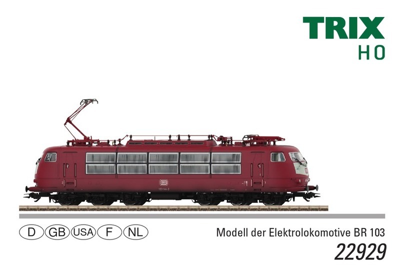
Trix Minitrix RAm Series User manual

Modell der BB II, BR 98.7
12320

2

3
Sommaire : Page
Informations concernant la locomotive réelle 5
Remarques importantes sur la sécurité 10
Informations générales 10
Fonctionnement 10
Remarques relatives au fonctionement en mode digital 10
Variables de configuration (CVs) 11
Entretien et maintien 14
Pièces de rechange 20
Inhoudsopgave: Pagina
Informatie van het voorbeeld 5
Veiligheidsvoorschriften 12
Algemene informatie 12
Functies 12
Aanwijzingen voor digitale besturing 12
Configuratie variabelen (CV’s) 13
Onderhoud en handhaving 14
Onderdelen 20
Inhaltsverzeichnis: Seite
Informationen zum Vorbild 4
Sicherheitshinweise 6
Allgemeine Hinweise 6
Funktionen 6
Hinweise zum Digitalbetrieb 6
Configurations Variablen (CVs) 7
Wartung und Instandhaltung 14
Ersatzteile 20
Table of Contents: Page
Information about the prototype 4
Safety Notes 8
General Notes 8
Functions 8
Notes on digital operation 8
Configuration Variables (CVs) 9
Service and maintenance 14
Spare Parts 20

4
Informationen zum Vorbild
Im Rahmen des Ausbaus der bayerischen Lokalbahnen wurden
zunehmend Lokomotiven benötigt, die starke Steigungen und
enge Radien bewältigen konnten. Maffei baute daraufhin eine
4-Zylinder-Verbund-Lokomotive der Bauart Mallet.
Der hintere feste Hauptrahmen trug die Hochdruckzylinder und
im vorderen beweglichen Antriebsdrehgestell waren die Nieder-
druckzylinder angeordnet. Da diese Lokomotiven jedoch sehr un-
ruhig liefen und zum Entgleisen neigten, wurden sie von der DRG
schon Mitte der 30er-Jahre des letzten Jahrhunderts wieder
ausgemustert und größtenteils als Werkslokomotiven verkauft.
So z.B. die „Zuckersusi“, die an die Zuckerfabrik Regensburg
geliefert wurde. Sie war dort bis 1972 im Dienst und steht heute
bei der Deutschen Museums-Eisenbahn in Darmstadt.
Achsanordnung B‘B
Länge ü. Puffer 10.010 mm
Höchstgeschwindigkeit 45 km/h
Dienstmasse 42,6 t
Nennleistung 265 kW (380 PS)
Baujahr ab 1899
Wheel arrangement 0-4-4-0T
Length over the buffers 10.010 mm / 32 ft. 10-1/8 in.
Maximum speed 45 km/h / 28 mph
Service weight 42.6 metric tons
Nominal power 265 kilowatts / 380 hp
Built starting in 1899
Information about the Prototype
As part of the expansion of the Bavarian Local Railroad, there
was an increasing need for locomotives capable of mastering
the steep grades and sharp curves on this railroad. Maffei built a
4-cylinder compound Mallet design locomotive for this purpose.
The rear rigid main frame supported the high pressure cylinders
and the low pressure cylinders were located in the front pivoting
frame. Since these locomotives were not very smooth in their
operation and since they had a tendency to derail, they were re-
tired by the DRG as early as the mid-1930s and were sold for the
most part as industrial locomotives. An example is the “Sugar
Susie”, which was sold to the Regensburg Sugar Refinery. It was
in service there until 1972 and is now at the German Railroad
Museum in Darmstadt.

5
Disposition d‘essieux B‘B
Longueur hors tampons 10.010 mm
Vitesse maximale 45 km/h
Poids en ordre de marche 42,6 t
Puissance nominale 265 kW (380 CV)
Construction à partir de 1899
Asindeling B’B
Lengte over de buffers 10.010 mm
Maximumsnelheid 45 km/h
Dienstgewicht 42,6 t
Normvermogen 265 kW (380 pk)
Bouwjaar vanaf 1899
Informations concernant le modèle réelle
L‘achèvement du réseau ferré local bavarois nécessitait un
nombre croissant de locomotives capables de rouler sur les
courbes serrées et de vaincre les sévères rampes de ce réseau.
Maffei a ainsi construit une série de locomotives à
4 cylindres compound du type Mallet.
Le groupe moteur fixe logé à l‘arrière était mû par les deux
cylindres à haute pression tandis le groupe moteur articulé situé
à l‘avant était entraîné par les deux cylindres à basse pression.
Du fait que ces locomotives se comportaient très irrégulière-
ment et déraillaient facilement, la DRG les a réformées vers le
milieu des années trente du siècle passé et en grande partie
revendues comme locomotives d‘usine. C‘est ainsi que la «Zuc-
kersusi», par exemple, est arrivée sur les rails de la fabrique de
sucre Regensburg. Elle y est restée en service jusqu‘en 1972 et
est actuellement remisée au Deutsche Museums-Eisenbahn à
Darmstadt.
Informatie over het voorbeeld
In het kader van de uitbreiding van de Beierse lokaalspoorwe-
gen waren steeds meer locomotieven nodig die opgewassen
waren tegen de sterk stijgende trajecten met hun krappe boch-
ten. Maffei bouwde daarvoor een 4-cilinder locomotief met twee
gekoppelde drijfwerken van de bouwserie Mallet.
Het achterste vaste hoofddrijfwerk droeg de hogedrukcilinders
en het voorste beweegbare aandrijfwerk de lagedrukcilinders.
Aangezien de locomotieven echter zeer onrustig liepen en de
neiging hadden te ontsporen, werden ze al in het midden van de
dertiger jaren van de twintigste eeuw door de DRG buiten dienst
genomen en grotendeels verkocht als fabriekslocomotieven.
Zo werd bijvoorbeeld de “Zuckersusi” aan de suikerfabriek
Regensburg verkocht. Deze was daar tot 1972 in dienst en staat
tegenwoordig bij de Duitse Museumspoorweg in Darmstadt.

6
Sicherheitshinweise
• DieLokdarfnurmiteinemdafürbestimmtenBetriebssystem
eingesetzt werden.
• DieLokdarfnichtmitmehralseinerLeistungsquelleversorgt
werden.
• BeachtenSieunbedingtdieSicherheitshinweiseinder
Gebrauchsanleitung zu Ihrem Betriebssystem.
• FürdenkonventionellenBetriebderLokmussdasAnschluss-
gleis entstört werden. Dazu ist das Entstörset 14972 zu ver-
wenden. Für Digitalbetrieb ist das Entstörset nicht geeignet.
• SetzenSiedasModellkeinerdirektenSonneneinstrahlung,
starken Temperaturschwankungen oder hoher Luftfeuchtig-
keit aus.
• ACHTUNG! Funktionsbedingte scharfe Kanten und Spitzen.
Allgemeine Hinweise
• DieBedienungsanleitungistBestandteildesProduktes
und muss deshalb aufbewahrt sowie bei Weitergabe des
Produktes mitgegeben werden.
• FürReparaturenoderErsatzteilewendenSiesichbittean
Ihren Trix-Fachhändler.
• http://www.maerklin.com/en/imprint.html
Funktionen
• EingebauteElektronikzumwahlweisenBetriebmitkonventi-
onellem Gleichstrom-Fahrgerät (max. ±12 Volt), Trix Systems,
Trix Selectrix oder Digitalsystemen nach NMRA-Norm.
• AutomatischeSystemerkennungzwischenDigital-und
Analog-Betieb.
• KeineautomatischeSystemerkennungzwischenSelectrix
(SX) und DCC.
• Zweilicht-Spitzensignalvorneundhinten,mitderFahrtrich-
tung wechselnd.
Hinweise zum Digitalbetrieb
• BeimerstenBetriebineinemDigital-System(Selectrixoder
DCC) muss der Decoder auf dieses Digital-System eingestellt
werden. Dazu ist der Decoder einmal in diesem Digitalsystem
zu programmieren (z.B. Adresse ändern).
• DerBetriebmitgegenpoligerGleichspannungimBremsab-
schnitt ist mit der werkseitigen Einstellung nicht möglich. Ist
diese Eigenschaft gewünscht, so muss auf den konventionellen
Gleichstrombetrieb verzichtet werden (CV 29 / Bit 2 = 0).
Jegliche Garantie-, Gewährleistungs- und Schadensersatzansprüche sind
ausgeschlossen, wenn in Trix-Produkten nicht von Trix freigegebene Fremd-
teile eingebaut werden und / oder Trix-Produkte umgebaut werden und die
eingebauten Fremdteile bzw. der Umbau für sodann aufgetretene Mängel
und / oder Schäden ursächlich war. Die Darlegungs- und Beweislast dafür,
dass der Einbau von Fremdteilen oder der Umbau in bzw. von Trix-Produkten
für aufgetretene Mängel und/oder Schäden nicht ursächlich war, trägt die
für den Ein- und / oder Umbau verantwortliche Person und/ oder Firma bzw.
der Kunde.

7
CV Bedeutung Wert DCC ab Werk
DCC / SX Wert
Selectrix
1 Adresse 1 - 127 3 / 1 1 - 99
3 Anfahrverzögerung 0 - 255 3 31 - 7
4 Bremsverzögerung 0 - 255 4 1 - 7
5 * Maximalgeschwindigkeit 0 - 127 127 / 7 1 - 7
17 Erweiterte Adresse (oberer Teil) CV 29, Bit 5=1 195 / —
nicht notwendig
18 Erweiterte Adresse (unterer Teil) CV 29, Bit 5=1 0 / —
nicht notwendig
29
Bit0:UmpolungFahrtrichtung
Bit1:AnzahlFahrstufen14/28
Bit2:DCCBetriebmitBremsstrecke
DCC-, Selectrix- und Gleichstrombetrieb
Bit5:Adressumfang7Bit/14Bit
Wert
0 / 1
0 / 2
0 / 4
0 / 32
***
0, 1, 2, 3, 4, 5, 6, 7,
32, 34, 35, 36, 37,
38, 39
6 / — nicht
notwendig
49 * Impulsbreite zur Motorsteuerung 0 - 3 1 / 2 1 - 4
50 * Regelvariante 0 - 3 2 / 3 1 - 4
51 * Bit0:Motorumpolung
Bit1:UmpolungLicht
Bit2:UmpolungGleis
0 / 1
0 / 2
0 / 4
***
0 - 7 0 / 4
nicht
notwendig
* Änderungen unter Selectrix führen automatisch auch zu Änderungen unter DCC und umgekehrt.
*** Die Werte der gewünschten Einstellungen sind zu addieren!

8
Functions
• Built-inelectroniccircuitforoperationwithaconventional
DC power pack (max. ±12 volts), Trix Systems, Trix Selectrix
or NMRA DCC digital systems.
• Automaticsystemrecognitionbetweendigitalandanalog
operation.
• NoautomaticsystemrecognitionbetweenSelectrix(SX)and
DCC.
• Dualheadlightsfrontandrear,thatchangeoverwiththe
direction of travel.
Notes on digital operation
• Thersttimethelocomotiveisusedinadigitalsystem
(Selectrix or DCC), the decoder must be set for this digital
system. To do this, the decoder must be programmed once in
thisdigitalsystem(Example:changinganaddress).
• Thesettingdoneatthefactorydoesnotpermitoperationwith
opposite polarity DC power in the braking block. If you want
this characteristic, you must do without conventional DC
power operation (CV 29 / Bit 2 = 0).
No warranty or damage claims shall be accepted in those cases where parts
neither manufactured nor approved by Trix have been installed in Trix pro-
ducts or where Trix products have been converted in such a way that the
non-Trix parts or the conversion were causal to the defects and / or damage
arising. The burden of presenting evidence and the burden of proof thereof,
that the installation of non-Trix parts or the conversion in or of Trix products
was not causal to the defects and / or damage arising, is borne by the person
and/or company responsible for the installation and / or conversion, or by
the customer.
Safety Notes
• Thislocomotiveisonlytobeusedwiththeoperatingsystem
it is designed for.
• Thislocomotivemustnotbesuppliedwithpowersimultane-
ously by more than one power source.
• Pleasemakenoteofthesafetyinformationintheinstructions
for your operating system.
• Thefeedertrackmustbeequippedtopreventinterference
with radio and television reception, when the locomotive is to
be run in conventional operation. The 14972 interference sup-
pression set is to be used for this purpose. The interference
suppression set is not suitable for digital operation.
• Donotexposethemodeltodirectsunlight,extremechanges
in temperature, or high humidity.
• WARNING! Sharp edges and points required for operation.
General Notes
• Theoperatinginstructionsareacomponentpartofthe
product and must therefore be kept in a safe place as well
as included with the product, if the latter is given to someone
else.
• PleaseseeyourauthorizedTrixdealerforrepairsorspare
parts.
• http://www.maerklin.com/en/imprint.html

9
CV Discription DCC Value Factory
Setting, DCC
/ SX
Selectrix Value
1 address 1 - 127 3 / 1 1 - 99
3 acceleration delay 0 - 255 3 31 - 7
4 braking delay 0 - 255 4 1 - 7
5 * maximum speed 0 - 127 127 / 7 1 - 7
17 extendet address (upper part) CV 29, Bit 5=1 195 / — not necessary
18 extendet address (lower part) CV 29, Bit 5=1 0 / — not necessary
29
Bit0:Traveldirectionpolarityreversal
Bit1:numberofspeedlevels14/28
Bit2:DCCOperationwithbrakingBlock
DCC-, Selectrix and DC power operation
Bit5:addresssize7Bit/14Bit
Value
0 / 1
0 / 2
0 / 4
0 / 32
***
0, 1, 2, 3, 4, 5, 6, 7,
32, 34, 35, 36, 37,
38, 39
6 / — not
necessary
49 * pulse width for motor control 0 - 3 1 / 2 1 - 4
50 * Rule variant 0 - 3 2 / 3 1 - 4
51 * Bit0:motorpolarityreversal
Bit1:lightingpolarityreversal
Bit2:trackpolarityreversal
0 / 1
0 / 2
0 / 4
***
0 - 7 0 / 4
not necessary
* Changes done under Selectrix will automatically be carried out under DCC and vice versa.
*** The values for the desired settings must be added.

10
Remarques importantes sur la sécurité
• Lalocomotivenepeutêtreutiliséequ‘aveclesystème
d‘exploitation indiqué.
• Lalocomotivenepeutpasêtrealimentéeélectriquementpar
plus d‘une source de courant à la fois.
• Ilestimpératifdetenircomptedesremarquessurla
sécurité décrites dans le mode d‘emploi de votre système
d‘exploitation.
• Pourl’exploitationdelalocomotiveenmodeconventionnel,
lavoiederaccordementdoitêtredéparasitée.Aceteffet,uti-
liser le set de déparasitage réf. 14972. Le set de déparasitage
ne convient pas pour l’exploitation en mode numérique.
• Nepasexposerlemodèleàunensoleillementdirect,àde
fortes variations de température ou à un taux d‘humidité
important.
• ATTENTION! Pointes et bords coupants lors du fonctionne-
ment du produit.
Informations générales
• Lanoticed‘utilisationfaitpartieintégranteduproduit;elle
doitdoncêtreconservéeet,lecaséchéant,transmiseavec
le produit.
• Pourtouteréparationouremplacementdepièces,adressez
vous à votre détaillant-spécialiste Trix.
• http://www.maerklin.com/en/imprint.html
Fonctionnement
• Electroniqueintégréepourexploitationauchoixavec
transformateur-régulateur conventionnel délivrant du courant
continu (max. ±12 volts), avec Trix Systems, avec Trix Selec-
trix ou avec des systèmes de conduite digitale conformes aux
normes NMRA.
• Reconnaissanceautomatiquedusystèmeentreexploitations
numérique et analogique.
• Pasdereconnaissanceautomatiqueentrelessystèmes
Selectrix (SX) et DCC.
• Feuxdoublesàl‘avantetàl‘arrière,avecalternanceselon
sens de marche.
Remarques relatives au fonctionnement en mode digital
• Unepremièreexploitationensystèmenumérique(Selectrix
ou DCC) exige le réglage correspondant du décodeur. A cet
effet,ledécodeurdoitêtreprogramméunefoisdansce
système numérique (par ex., modifier l’adresse).
• L’exploitationaveccourantcontinudepolaritéinversedansles
sections de freinage n’est pas possible avec le réglage d’usine. Si
cette propriété est désirée, il faut alors renoncer à l’exploitation
conventionnelle en courant continu (CV 29 / Bit 2 = 0).
Tout recours à une garantie commerciale ou contractuelle ou à une deman-
dededommages-intérêtestexclusidespiècesnonautoriséesparTrixsont
intégrées dans les produits Trix et / ou si les produits Trix sont transformés
et si les pièces d’autres fabricants montées ou la transformation constitu-
ent la cause des défauts et/ou dommages apparus. C’est à la personne et
/ ou la société responsable du montage / de la transformation ou au client
qu’incombe la charge de prouver que le montage des pièces d’autres fabri-
cants sur des produits Trix ou la transformation des produits Trix n’est pas à
l’origine des défauts et ou dommages apparus.
11
CV Signification Valeur DCC Valeur Parm. Usine
DCC / SX Selectrix Valeur
1 Adresse 1 - 127 3 / 1 1 - 99
3 Temporisation d‘accélération 0 - 255 3 31 - 7
4 Temporisation de freinage 0 - 255 4 1 - 7
5 * Vitesse maximale 0 - 127 127 / 7 1 - 7
17 Adresse étendue (partie supérieure) CV 29, Bit 5=1 195 / — pas nécessaire
18 Adresse étendue (partie inférieure) CV 29, Bit 5=1 0 / — pas nécessaire
29
Bit0:inversiondepolarité,sensdemarche
Bit1:Nombredecransdemarche14/28
Bit2:ExploitationDCCaveczonedefreinage
DCC-, Selectrix et courant continu
Bit5:tailled‘adresse7Bits/14Bits
Valeur
0 / 1
0 / 2
0 / 4
0 / 32
***
0, 1, 2, 3, 4, 5, 6, 7,
32, 34, 35, 36, 37,
38, 39
6 / — pas
nécessaire
49 * Largeur d‘impulsion de commande moteur 0 - 3 1 / 2 1 - 4
50 * Variante de réglage 0 - 3 2 / 3 1 - 4
51 * Bit0:inversiondepolaritédumoteur
Bit1:pharesseulement
Bit2:inversiondepolaritè
0 / 1
0 / 2
0 / 4
***
0 - 7 0 / 4
pas nécessaire
* Toute modification effectuée sous Selectrix entraîne automatiquement une modification sous DCC et inversement.
*** Les valeurs des réglages désirés sont à additioner.

12
Veiligheidsvoorschriften
• Delocmagalleenmeteendaarvoorbestemdbedrijfssysteem
gebruikt worden.
• Delocmagnietvanuitmeerdanéénstroomvoorziening
gelijktijdig gevoed worden.
• Leesookaandachtigdeveiligheidsvoorschriftenindegebru-
iksaanwijzing van uw bedrijfssysteem.
• Voorhetconventionelebedrijfmetdelocdientdeaansluitrail
te worden ontstoort. Hiervoor dient men de ontstoor-set
14972 te gebruiken. Voor het digitale bedrijf is deze ontstoor-
set niet geschikt.
• Stelhetmodelnietblootaanindirectezonnestraling,sterke
temperatuurwisselingen of hoge luchtvochtigheid.
• OPGEPAST! Functionele scherpe kanten en punten.
Algemene informatie
• Degebruiksaanwijzingiseenessentieelonderdeelvan
het product en dient daarom bewaard te worden en bij het
overdragen van het product meegegeven te worden.
• VoorreparatiesenonderdelenkuntzichtotUwTrixhandelaar
wenden.
• http://www.maerklin.com/en/imprint.html
Functies
• Ingebouwdeelektronicadiehetmogelijkmaaktomnaar
keuze met, een conventionele gelijkstroomrijregelaar (max.
±12 Volt), Trix Systems, Trix Selectrix of digitaalsysteem
volgens NMRA-norm te rijden.
• Automatischesysteemherkenningtussendigitaal-enana-
loogbedrijf.
• GeenautomatischeherkenningtussenSelectrix(SX)enDCC.
• Tweevoudigefrontverlichtingvoorenachter,wisselendmet
de rijrichting.
Aanwijzingen voor digitale besturing
• Voorheteerstebedrijfmeteendigitaal-systeem(Selectrix
of DCC) moet de decoder op dat digitale systeem worden in-
gesteld. Daarvoor moet de decoder éénmaal met dat digitale
systeem geprogrammeerd worden (bijv. adres wijzigen).
• Hetbedrijfmettegengepooldegelijkspanningindeafrem-
sectie is met de fabrieksinstelling niet mogelijk. Indien deze
eigenschap wenselijk is, dan moet worden afgezien van het
conventioneel gelijkstroombedrijf (CV 29 / Bit 2 = 0).
Elke aanspraak op garantie en schadevergoeding is uitgesloten, wanneer in
Trix-producten niet door Trix vrijgegeven vreemde onderdelen ingebouwd
en / of Trix-producten omgebouwd worden en de ingebouwde vreemde on-
derdelen resp. de ombouw oorzaak van nadien opgetreden defecten en / of
schade was. De aantoonplicht en de bewijslijst daaromtrent, dat de inbouw
van vreemde onderdelen in Trix-producten of de ombouw van Trix-producten
niet de oorzaak van opgetreden defecten en / of schade is geweest, berust
bij de voor de inbouw en / of ombouw verantwoordelijke persoon en / of
firma danwel bij de klant.

13
CV Betekenis Waarde DCC Af fabriek
DCC/Sx Waarde
Selectrix
1 adres 1 - 127 3 / 1 1 - 99
3 optrekvertraging 0 - 255 3 31 - 7
4 afremvertraging 0 - 255 4 1 - 7
5 * maximumsnelheid 0 - 127 127 / 7 1 - 7
17 uitgebreld adres (bovenste gedeelte) CV 29, Bit 5=1 195 / — niet nodig
18 uitgebreld adres (onderste gedeelte) CV 29, Bit 5=1 0 / — niet nodig
29
Bit0:ompolingrijrichting
Bit1:aantalrijstappen14/28
Bit2:DCC-bedrijfmetafremtraject
DCC-, Selectrix- en gelijkstroombedrijf
Bit5:adresbereik7Bit/14Bit
Waarde
0 / 1
0 / 2
0 / 4
0 / 32
***
0, 1, 2, 3, 4, 5, 6, 7,
32, 34, 35, 36, 37,
38, 39
6 / — niet nodig
49 * impulsbreedte voor de motorsturing 0 - 3 1 / 2 1 - 4
50 * relingsvariant 0 - 3 2 / 3 1 - 4
51 * Bit0:motorompoling
Bit1:allenverlichting
Bit2:ompolingrails
0 / 1
0 / 2
0 / 4
***
0 - 7 0 / 4
niet nodig
* Wijzigingen doorgevoerd met Selectrix leiden automatisch tot wijzigingen bij DCC en omgekeerd.
*** De waarde van de gewenste instellingen moeten bij elkaar opgeteld worden.

14
66625 66626
Spezialöl
mit Tropfnadel
O
I
L
MINITRIX
66623
40h

15
ab
c
c
ab

16

17
Beim Zusammenbau auf die korrekte Kabelführung achten.
Be careful that the wiring is routed correctly when assembling the locomotive.
Lors de l‘assemblage, attention à la position correcte des câbles.
Bij het in elkaar zetten op de juiste positie van de bedrading letten.

18
Beim Zusammenbau auf die korrekte Kabelführung achten.
Be careful that the wiring is routed correctly when assembling the locomotive.
Lors de l‘assemblage, attention à la position correcte des câbles.
Bij het in elkaar zetten op de juiste positie van de bedrading letten.
a
b

19
1 Führerstand komplett 149 600
2 Lampe 14 0869 28
3 Glocke 14 0883 28
4 Sortiment Kleinteile 315 529
5 Sortiment Glasteile 151 615
6 Wasserkasten links 151 622
7 Wasserkasten rechts 151 623
8 Kessel komplett 148 806
9 Pfeife 14 0674 24
10 Rauchkammertür 12 6092 00
11 Schornstein 12 6094 00
12 Lampen 151 618
13 Motor mit Schnecken 148 823
14 Decoder 148 819
15 Schraube 19 8326 28
16 Bügel 15 0977 00
17 Klammer 12 6083 00
18 Halter 148 261
19 Glühlampe 15 0250 00
20 Feder 15 0921 00
21 Deckel mit Leitung 148 816
22 Kupplung 12 2103 00
23 Feder 15 0227 00
24 Lokrahmen 315 208
25 Schleiferplatte 149 748
26 Schraube 19 7094 08
27 Schleiferfeder links 13 2788 15
28 Schraube 19 8325 28
29 Aufnahme 31 2834 14
30 Schieber links 12 6074 00
31 Schieber rechts 12 6073 00
32 Steuerung hinten links 315 523
33 Zylinder links hinten 12 6089 00
34 Steuerung hinten rechts 315 524
35 Zylinder rechts hinten 12 6088 00
36 Schraube 19 7092 08
37 Steuerung für Drehgestell 315 526
38 Drehgestell komplett 151 619
39 Puffer 14 0700 28
40 Zwischenrad 12 6072 00
41 Achse 14 0886 00
42 Zylinder links vorn 12 6087 00
43 Zylinder rechts vorn 12 6086 00
44 Radsatz 148 814
45 Kuppelstange links 315 235
46 Kuppelstange rechts 315 234
47 Kopfstift 14 0726 28
48 Achshalter hinten 315 207
49 Achshalter vorn 315 241
50 Schraube 19 8324 28

Gebr. Märklin & Cie. GmbH
Stuttgarter Straße 55 - 57
73033 Göppingen
Deutschland
www.trix.de
149605/0311/Sm2Ef
Änderungen vorbehalten
© Gebr. Märklin & Cie. GmbH
1
12
2
4
3
4
5
5
6
7
8
14
18
9
10
12
15
16
19
22
21
19
20
36
35
3327
46
46
12
12
47
47
47
44
45
44
45
48
50
50
49
47
38
39
39
22
23
25
23
23
43
41
40
42
44
24
30
17
29
31
26 28
34
37
32
13
11
Details der Darstellung
können von dem Modell
abweichen.
Other manuals for Minitrix RAm Series
1
This manual suits for next models
2
Table of contents
Languages:
Other Trix Toy manuals

Trix
Trix Minitrix 66140 User manual

Trix
Trix 21523 User manual

Trix
Trix H0 Elefant C 5/6 User manual

Trix
Trix BR 420 User manual

Trix
Trix 220 Series User manual

Trix
Trix 23490 User manual

Trix
Trix BR 41 User manual

Trix
Trix Ce 6/8 II Series User manual

Trix
Trix Minitrix BR 250/155 User manual

Trix
Trix 3600 Series User manual

Trix
Trix BR 042 User manual

Trix
Trix BR 189 User manual

Trix
Trix Minitrix 66540 User manual

Trix
Trix VT98 DB User manual

Trix
Trix BR 85 User manual

Trix
Trix Gt 2 x 4/4 BR 96 User manual

Trix
Trix 22141 User manual

Trix
Trix BR 89.0 User manual

Trix
Trix H0 94.5 Series User manual

Trix
Trix Re 421 Series User manual