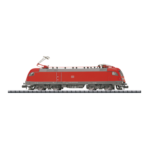
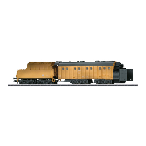
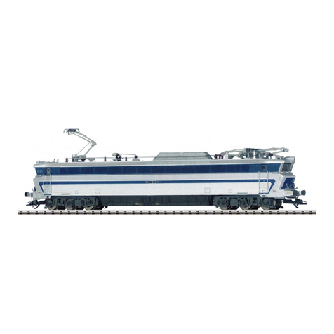
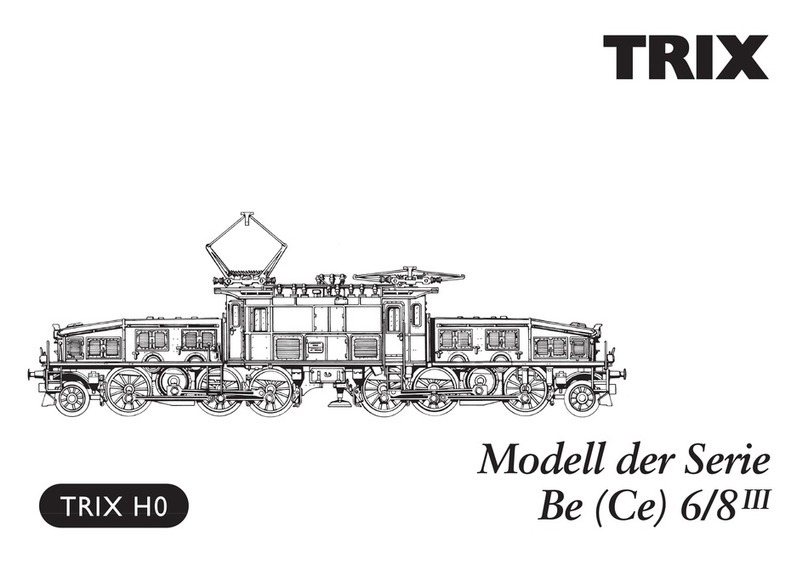
Trix Ce 6/8 II Series User manual

Modell der Elektrolokomotive Serie Ce 6/8 II
22967
F
D GB USA NL

2

3
Hinweis: Vor dem ersten Betrieb der Lok müssen die
Pantographen von Hand entriegelt werden. Der Pantograph
federt selbst in die obere Stellung hoch.
Beim Verpacken ist immer darauf zu achten, dass die
Stromabnehmer elektronisch ausgefahren sind und erst
dann von Hand eingefahren (verriegelt) werden.
Note: Before running the locomotive for the first time, the
pantographs must be unlocked by hand. The pantograph
flexes upwards on its own in the upper position.
When packing the locomotive, always make sure that the
pantographs have been raised electronically and then you
can lower them by hand and lock them in place.
Remarque : Avant la première exploitation de la loco, les
pantographes doivent être déverrouillés à la main. Le
pantographe se met alors directement en position haute
(ressort).
Lors de l’emballage, veillez toujours à ce que les
pantographes aient été dépliés électroniquement avant de
les replier (verrouiller) à la main.
Opmerking: Voor het eerste gebruik van de loc moeten de
pantografen handmatig ontgrendeld worden. De pantograaf
veert vanzelf in de hoogste stand.
Voor het verpakken dient er altijd op gelet te worden dat de
pantografen elektronisch omhoog gebracht zijn en daarna
pas handmatig naar beneden gebracht (vergrendeld)
moeten worden.

4

5
Inhaltsverzeichnis Seite
Betriebshinweise 2
Sicherheitshinweise 6
Wichtige Hinweise 6
Multiprotokollbetrieb 6
Schaltbare Funktionen 9
Parameter/Register 10
Ergänzendes Zubehör 26
Wartung und Instandhaltung 27
Ersatzteile 33
Table of Contents Page
Information about operation 2
Safety Notes 11
Important Notes 11
Multi-Protocol Operation 11
Controllable Functions 14
Parameter/Register 15
Complementary accessories 26
Service and maintenance 27
Spare Parts 33
Sommaire Page
Remarques sur l’exploitatione 2
Remarques importantes sur la sécurité 16
Information importante 16
Mode multiprotocole 16
Fonctions commutables 19
Paramètre/Registre 20
Accessoires complémentaires 26
Entretien et maintien 27
Pièces de rechange 33
Inhoudsopgave Pagina
Opmerkingen over de werking 2
Veiligheidsvoorschriften 21
Belangrijke aanwijzing 21
Multiprotocolbedrijf 21
Schakelbare functies 24
Parameter/Register 25
Aanvullende toebehoren 26
Onderhoud en handhaving 27
Onderdelen 33

6
Sicherheitshinweise
• DieLokdarfnurmiteinemdafürbestimmtenBetriebssys-
tem eingesetzt werden.
• Analogmax.15Volt=,digitalmax.22Volt~.
• DieLokdarfnurauseinerLeistungsquelleversorgt
werden.
• BeachtenSieunbedingtdieSicherheitshinweiseinder
Bedienungsanleitung zu Ihrem Betriebssystem.
• FürdenkonventionellenBetriebderLokmussdasAn-
schlussgleis entstört werden. Dazu ist das Entstörset
611 655 zu verwenden. Für Digitalbetrieb ist das Entstör-
set nicht geeignet.
• ACHTUNG! Funktionsbedingte scharfe Kanten und Spitzen.
• SetzenSiedasModellkeinerdirektenSonneneinstrah-
lung, starken Temperaturschwankungen oder hoher
Luftfeuchtigkeit aus.
• VerbauteLED`sentsprechenderLaserklasse1nach
Norm EN 60825-1.
• DerArtikelverfügtübereinenDecodermitmtc21-
Schnittstelle. Die enthaltenen Decoderausgänge steuern
verschiedene zusätzliche Funktionen an. Nur bei Verwen-
dung des artikelspezifischen Märklin/Trixdecoders mit
seiner speziell darauf abgestimmten SW-Konfiguration
ist ein ordnungsgemäßer Betrieb dieser Zusatzfunktionen
gewährleistet. Die Verwendung anderer Komponenten
kann zu Beschädigungen führen!
Wichtige Hinweise
• DieBedienungsanleitungunddieVerpackungsind
Bestandteile des Produktes und müssen deshalb aufbe-
wahrt sowie bei Weitergabe des Produktes mitgegeben
werden.
• FürReparaturenoderErsatzteilewendenSiesichbittean
Ihren Trix-Fachhändler.
• GewährleistungundGarantiegemäßderbeiliegenden
Garantieurkunde.
• Entsorgung:www.maerklin.com/en/imprint.html
• DervolleFunktionsumfangistnurunterDCCundunter
mfx verfügbar.
• Eingebaute,fahrtrichtungsabhängigeStirnbeleuchtung.
Im Digitalbetrieb schaltbar.
• ImAnalogbetriebstehennurdieFahr-undLichtwechsel-
funktionen zur Verfügung.
• DieLokistnichtaufOberleitungsbetriebumschaltbar.
• BefahrbarerMindestradius360mm.
Multiprotokollbetrieb
Analogbetrieb
DerDecoderkannauchaufanalogenAnlagenoderGleis-
abschnitten betrieben werden. Der Decoder erkennt die
analogeGleichspannung(DC)automatischundpasstsich
deranalogenGleisspannungan.EssindalleFunktionen,
die unter mfx oder DCC für den Analogbetrieb eingestellt
wurden aktiv (siehe Digitalbetrieb).

7
Digitalbetrieb
Der Decoder ist ein Multiprotokolldecoder. Der Decoder
kannunterfolgendenDigital-Protokolleneingesetztwerden:
mfx, DCC oder MM.
AdresseabWerk:DCC 03 / MM 68 (69)
Das Digital-Protokoll mit den meisten Möglichkeiten ist das
höchstwertige Digital-Protokoll. Die Reihenfolge der Digital-
ProtokolleistinderWertungfallend:
Priorität1:mfx
Priorität2:DCC
Priorität3:MM
Hinweis: Werden zwei oder mehrere Digital-Protokolle am
Gleiserkannt,übernimmtderDecoderautomatischdas
höchstwertige Digital-Protokoll; z.B. wird mfx & DCC erkannt
wird das mfx-Digital-Protokoll vom Decoder übernommen.
Einzelne Protokolle können über den Parameter CV 50
deaktiviert werden.
Hinweis: Beachten Sie, dass nicht alle Funktionen in allen
Digital-Protokollen möglich sind. Unter mfx und DCC können
einige Einstellungen von Funktionen, welche im Analog-
Betrieb wirksam sein sollen, vorgenommen werden.
Hinweise zum Digitalbetrieb
• DiegenaueVorgehensweisezumEinstellenderdiversen
Parameter entnehmen Sie bitte der Bedienungsanleitung
Ihrer Mehrzug-Zentrale.
• DerBetriebmitgegenpoligerGleichspannungim
Bremsabschnitt ist mit der werkseitigen Einstellung
nicht möglich. Ist diese Eigenschaft gewünscht, so muss
aufdenkonventionellenGleichstrombetriebverzichtet
werden(CV29/Bit2=0).
mfx-Protokoll
Adressierung
• KeineAdresseerforderlich,jederDecodererhälteine
einmalige und eindeutige Kennung (UID).
• DerDecodermeldetsichaneinerCentralStationoder
Mobile Station mit seiner UID automatisch an.
• NameabWerk:Ce 6/8 II 14282
Programmierung
• DieEigenschaftenkönnenüberdiegrascheOberäche
der Central Station bzw. teilweise auch mit der Mobile
Station programmiert werden.
• EskönnenalleCongurationVariablen(CV)mehrfach
gelesen und programmiert werden.
• DieProgrammierungkannentwederaufdemHaupt-oder
dem Programmiergleis erfolgen.
• DieDefaulteinstellungen(Werkseinstellungen)können
wieder hergestellt werden.
• Funktionsmapping:FunktionenkönnenmitHilfeder
Central Station 60212 (eingeschränkt) und mit der Central
Station 60213/60214/60215/60216/60226 beliebigen Funkti-
onstasten zugeordnet werden (siehe Hilfe in der Central
Station).
8
DCC-Protokoll
Adressierung
• MöglicheAdressen:Kurze,langeundTraktionsadresse
• Adressbereich:
1 – 127 (kurze Adresse, Traktionsadresse)
1 – 10239 (lange Adresse)
• JedeAdresseistmanuellprogrammierbar.
• KurzeoderlangeAdressewirdüberdieCVsausgewählt.
• EineangewandteTraktionsadressedeaktiviertdie
Standard-Adresse.
Programmierung
• DieEigenschaftenkönnenüberdieCongurationsVari-
ablen (CV) mehrfach geändert werden.
• DieCV-NummerunddieCV-Wertewerdendirekteinge-
geben.
• DieCVskönnenmehrfachgelesenundprogrammiert
werden (Programmierung auf dem Programmiergleis).
• DieCVskönnenbeliebigprogrammiertwerden.PoM
(Programmierung auf dem Hauptgleis PoM) ist nur bei
den in der CV-Tabelle gekennzeichneten CV möglich.
PoM muss von Ihrer Zentrale unterstützt werden (siehe
BedienungsanleitungihresGerätes).
• DieDefaulteinstellungen(Werkseinstellungen)können
wieder hergestellt werden.
• 14bzw.28/126Fahrstufeneinstellbar.
• AlleFunktionenkönnenentsprechenddemFunktions-
mapping geschaltet werden.
• WeitereInformation,sieheCV-TabelleDCC-Protokoll.
Es wird empfohlen, die Programmierungen grundsätzlich auf
dem Programmiergleis vorzunehmen.
Logische Funktionen
Anfahr-/Bremsverzögerung
• DieBeschleunigungs-undBremszeitkönnengetrennt
von einander eingestellt werden.
• DielogischeFunktionsabschaltungABVkannüberdas
Funktionsmapping auf jede beliebige Funktionstaste
gelegt werden.

9
1Trix Systems
2Nur in Verbindung mit Spitzensignal /
Zusammengeschaltet:RangierlichtDoppelA.
Schaltbare Funktionen
DC/AC
MS I 1
MS II
CS I
CS II/III
Schweizer Lichtwechsel F0
Schlusslicht umschalten (1 x weiß ->
1 x rot) F1
Betriebsgeräusch F2
Geräusch:Lokpfeife F3
ABV, aus F4
Pantograph heben/senken F5
Telex-Kupplung Führerstand 1 F6
Geräusch:Rangierpff F7
Telex-Kupplung Führerstand 2 F8
Geräusch:Bremsenquietschenaus F9
Geräusch:PufferanPuffer F10
Geräusch:Kabinenfunk1 F11
Geräusch:Kabinenfunk2 F12
Geräusch:Lüfter F13
Pantograph-Geräusch(hoch/nieder) F14
Geräusch:Sanden F15
Geräusch:Schienenstöße F16
Schaltbare Funktionen
DC/AC
MS I 1
MS II
CS I
CS II/III
Geräusch:Druckluftablassen F17
Spitzensignal Führerstand 2 aus 2F18
Spitzensignal Führerstand 1 aus 2F19
Geräusch:Schaffnerpff F20
Pantograph heben/senken + Panto-
graph-Geräusch F21
Umgebungsgeräusch:Ablaufberg F22
Geräusch:Führerstandstüreauf/zu F23
Geräusch:Bahnhofsansage F24
Geräusch:Kompressor F25
Rangiergang F26

10
CV Bedeutung Wert DCC ab Werk
1 Adresse 1 - 127 3
2 PoM Minimalgeschwindigkeit 0 - 255 4
3 PoM Anfahrverzögerung 0 - 255 47
4 PoM Bremsverzögerung 0 - 255 47
5 PoM Maximalgeschwindigkeit 0 - 255 175
8 Werkreset/Herstellerkennung 8 131
13 PoM Funktionen F1 - F8 im Analogbetrieb 0 - 255 0
14 PoM Funktionen F9 - F15 und Licht im Analogbetrieb 0 - 255 1
17 Erweiterte Adresse (oberer Teil) CV29,Bit5=1 192
18 Erweiterte Adresse (unterer Teil) CV29,Bit5=1 128
19 Traktionsadresse 0 - 255 0
21 PoM Funktionen F1 - F8 bei Traktion 0 - 255 0
22 PoM Funktionen F9 - F15 und Licht bei Traktion 0 - 255 0
29 PoM
Bit0:UmpolungFahrtrichtung
Bit1:AnzahlFahrstufen14oder28/128*
Bit2:DCCBetriebmitBremsstrecke(keinAnalogbetriebmöglich)
Bit5:kurze/langeAdresse
0 / 1
0 / 2
0 / 4
0 / 32
0, 1, 2, 3, 4, 5, 6, 7,
32, 34, 35, 36, 37,
38, 39 6
50 PoM
Alternative Protokolle (DCC kann sich selber nicht deaktivieren)
Bit0:AnalogACaus=0/AnalogACein=1
Bit1:AnalogDCaus=0/AnalogDCein=1
Bit2:fx(MM)aus=0/fx(MM)ein=1
Bit3:mfxaus=0/mfxein=1
0 / 1
0 / 2
0 / 4
0 / 8
0 - 15 15
63 PoM Lautstärke 0 - 255 255
* FahrstufenamLokdecoderundamSteuergerätmüssenübereinstimmen,essindsonstFehlfunktionenmöglich.

11
Important Notes
• Theoperatinginstructionsandthepackagingareacom-
ponent part of the product and must therefore be kept as
well as transferred along with the product to others.
• PleaseseeyourauthorizedTrixdealerforrepairsor
spare parts.
• Thewarrantycardincludedwiththisproductspecies
the warranty conditions.
• Disposing:www.maerklin.com/en/imprint.html
• ThefullrangeoffunctionsisonlyavailableunderDCC
and mfx.
• Built-inheadlightsthatchangeoverwiththedirectionof
travel. They can be turned on and off in digital operation.
• Onlythetraincontrolfunctionsandheadlightchangeover
feature are available in analog operation.
• Thelocomotivecannotbeswitchedtooperationfrom
catenary.
• Minimumradiusforoperationis360mm/14-3/16“.
Multi-Protocol Operation
Analog Operation
This decoder can also be operated on analog layouts or ar-
eas of track that are analog. The decoder recognizes alter-
nating current (DC) and automatically adapts to the analog
track voltage. All functions that were set under mfx or DCC
for analog operation are active (see Digital Operation).
Safety Notes
• Thislocomotiveisonlytobeusedwiththeoperating
system it is designed for.
• Analogmax.15voltsDC,digitalmax.22voltsAC.
• Thislocomotivemustneverbesuppliedwithpowerfrom
more than one power pack.
• Pleasemakenoteofthesafetynotesintheinstructions
for your operating system.
• Thefeedertrackmustbeequippedtopreventinter-
ference with radio and television reception, when the
locomotive is to be run in conventional operation. The
611 655 interference suppression set is to be used for this
purpose. The interference suppression set is not suitable
for digital operation.
• WARNING! Sharp edges and points required for operation.
• Donotexposethemodeltodirectsunlight,extreme
changes in temperature, or high humidity.
• TheLEDsinthisitemcorrespondtoLaserClass1accor-
ding to Standard EN 60825-1.
• Thisitemhasadecoderwithanmtc21interface.The
decoder outputs included on it control different auxiliary
functions. Correct operation of these auxiliary functions
is guaranteed only if you use the Märklin/Trixdecoder
specific to the item. The SW configuration on the decoder
is specially calibrated to that item. Using other compo-
nents may cause damage!

12
Digital Operation
The decoders are multi-protocol decoders. These decoders
canbeusedunderthefollowingdigitalprotocols:mfx,DCC
or MM.
Addresssetatthefactory:DCC 03 / MM 68 (69)
The digital protocol with the most possibilities is the highest
order digital protocol. The sequence of digital protocols in
descendingorderis:
Priority1:mfx
Priority2:DCC
Priority3:MM
Note: If two or more digital protocols are recognized in the
track, the decoder automatically takes on the highest value
digital protocol.For example, if mfx & DCC are recognized,
the mfx digital protocol is taken on by the decoder. Individual
protocols can be deactivated with Parameter CV 50.
Note: Please note that not all functions are possible in all
digital protocols. Several settings for functions, which are
supposed to be active in analog operation, can be done
under mfx and DCC.
Notes on digital operation
• Theoperatinginstructionsforyourcentralunitwillgive
you exact procedures for setting the different parame-
ters.
• Thesettingdoneatthefactorydoesnotpermitoperation
with opposite polarity DC power in the braking block.
If you want this characteristic, you must do without
conventionalDCpoweroperation(CV29/Bit2=0).
mfx Protocol
Addresses
• Noaddressisrequired;eachdecoderisgivenaone-
time, unique identifier (UID).
• ThedecoderautomaticallyregistersitselfonaCentral
Station or a Mobile Station with its UID.
• Namesetatthefactory:Ce 6/8 II 14282
Programming
• Thecharacteristicscanbeprogrammedusingthe
graphic screen on the Central Station or also partially
with the Mobile Station.
• AlloftheCongurationVariables(CV)canbereadand
programmed repeatedly.
• Theprogrammingcanbedoneeitheronthemaintrackor
the programming track.
• Thedefaultsettings(factorysettings)canbeproduced
repeatedly.
• Functionmapping:Functionscanbeassignedto
any of the function buttons with the help of the
60212 Central Station (with limitations) and with the
60213/60214/60215/60216/60226 Central Station (See help
section in the Central Station).
13
DCC Protocol
Addresses
• Possibleaddresses:short,long,andm.u.address
• Addressrange:
1 – 127 (short address, m.u. address)
1 – 10239 (long address)
• Everyaddresscanbeprogrammedmanually.
• AshortoralongaddressisselectedusingtheCVs.
• Amultipleunitaddressthatisbeinguseddeactivatesthe
standard address.
Programming
• Thecharacteristicscanbechangedrepeatedlyusingthe
Configuration Variables (CV).
• TheCVnumbersandtheCVvaluesareentereddirectly.
• TheCVscanbereadandprogrammedrepeatedly.(Pro-
gramming is done on the programming track.)
• TheCVscanbeprogrammed,asyoudesire.PoM(Pro-
gramming on the layout track) is only possible with those
CVs marked in the CV table. PoM must be supported
by your central controller (see the instructions for your
controller).
• Thedefaultsettings(factorysettings)canbeproduced
repeatedly.
• 14or28/126speedlevelscanbeset.
• Allofthefunctionscanbecontrolledaccordingtothe
function mapping (see CV description).
• SeetheCVdescriptionfortheDCCprotocolforadditional
information.
We recommend that in general programming should be
done on the programming track.
Logic Functions
Acceleration / Braking Delay
• Theaccelerationandbrakingtimescanbesetseparately
from each other.
• ThelogicalfunctionshutoffforABV(Acceleration/
Braking Delay) can be assigned to any function button by
means of function mapping.

14
1Trix Systems
2Only in conjunction with the headlights /
Switchedtogether:„DoubleA“switchinglights.
Controllable Functions
DC/AC
MS I 1
MS II
CS I
CS II/III
Swiss headlight changeover F0
Switching marker lights (1 x white ->
1 x red) F1
Operating sounds F2
Soundeffect:Locomotivewhistle F3
ABV, off F4
Pantograph raise/lower F5
Telex coupler Cab 1 F6
Soundeffect:Switchingwhistle F7
Telex coupler Cab 2 F8
Soundeffect:Squealingbrakesoff F9
Soundeffect:Buffertobuffer F10
Soundeffect:Cabradio1 F11
Soundeffect:Cabradio2 F12
Soundeffect:Blower F13
Pantograph sound (up/down) F14
Soundeffect:Sanding F15
Soundeffect:Railjoints F16
Controllable Functions
DC/AC
MS I 1
MS II
CS I
CS II/III
Soundeffect:Lettingoffair F17
Headlights Engineer‘s Cab 2 off 2F18
Headlights Engineer‘s Cab 1 off 2F19
Soundeffect:Conductorwhistle F20
Pantograph raise/lower + Pantograph
sound F21
Surroundingsounds:HumpTrack F22
Soundeffect:Open/Closecabdoors F23
Soundeffect:Stationannouncements F24
Soundeffect:Compressor F25
Low speed switching range F26

15
* Thespeedlevelsonthelocomotivedecoderandonthecontrollermustagreewitheachother;otherwise,
you may have malfunctions.
CV Discription DCC Value Factory-Set
1 Address 1 - 127 3
2 PoM Minimum Speed 0 - 255 4
3 PoM Acceleration delay 0 - 255 47
4 PoM Braking delay 0 - 255 47
5 PoM Maximum speed 0 - 255 175
8 Factory Reset / Manufacturer Recognition 8 131
13 PoM Functions F1 - F8 in analog operation 0 - 255 0
14 PoM Functions F9 - F15 and lights in analog operation 0 - 255 1
17 Extended address (upper part) CV29,Bit5=1 192
18 Extended address (lower part) CV29,Bit5=1 128
19 Multiple Unit Address 0 - 255 0
21 PoM Functions F1 - F8 on Multiple Unit 0 - 255 0
22 PoM Functions F9 - F15 and lights on Multiple Unit 0 - 255 0
29 PoM
Bit0:Reversingdirectionoftravel
Bit1:Numberofspeedlevels14or28/128*
Bit2:DCCoperationwithabrakingarea(noanalogoperation
possible)
Bit5:short/longaddress
0 / 1
0 / 2
0 / 4
0 / 32
0, 1, 2, 3, 4, 5, 6,
7, 32, 34, 35, 36,
37, 38, 39 6
50 PoM
Alternative Protocols (DCC cannot deactivate itself)
Bit0:AnalogACoff=0/AnalogACon=1
Bit1:AnalogDCoff=0/AnalogDCon=1
Bit2:fx(MM)off=0/fx(MM)on=1
Bit3:mfxoff=0/mfxon=1
0 / 1
0 / 2
0 / 4
0 / 8
0 - 15 15
63 PoM Volume 0 - 255 255

16
Remarques importantes sur la sécurité
• Lalocomotivenepeutêtreutiliséequ‘aveclesystème
d‘exploitation indiqué.
• Analogiquemax.15Volt=,digitalmax.22Volt~.
• Lalocomotivenepeutpasêtrealimentéeélectriquement
par plus d‘une source de courant à la fois.
• Ilestimpératifdetenircomptedesremarquessurla
sécurité décrites dans le mode d‘emploi de votre système
d‘exploitation.
•
Pour l’exploitation de la locomotive en mode convention-
nel, la voie de raccordement doit être déparasitée. A cet
effet, utiliser le set de déparasitage réf. 611 655. Le set de
déparasitage ne convient pas pour l’exploitation en mode
numérique.
•
ATTENTION! Pointes et bords coupants lors du fonctionne-
ment du produit.
• Nepasexposerlemodèleàunensoleillementdirect,
à de fortes variations de température ou à un taux
d‘humidité important.
• LesDELinstalléescorrespondentàlaclasselaser1
selon la norme EN 60825-1.
• L’articledisposed’undécodeuravecinterface21mtc.Les
sorties décodeur incluses commandent différentes fon-
ctions supplémentaires. Seule l’utilisation du décodeur
Märklin/Trix spécifique à l’article avec la configuration
SW spécialement adaptée garantit une exploitation
conforme de ces fonctions supplémentaires. L’utilisation
d’autres composants pourrait entraîner des détériora-
tions!
Information importante
• Lanoticed‘utilisationetl’emballagefontpartieintégrante
du produit ; ils doivent donc être conservés et, le cas
échéant, transmis avec le produit.
• Pourtouteréparationouremplacementdepièces,adres-
sez vous à votre détaillant-spécialiste Trix.
• Garantielégaleetgarantiecontractuelleconformément
au certificat de garantie ci-joint.
• Elimination:www.maerklin.com/en/imprint.html
• L’intégralitédesfonctionsestdisponibleuniquementen
exploitation DCC et mfx.
• Feuxdesignalisations‘inversantselonlesensdemar-
che; feux commutables en exploitation digital.
• Enmoded’exploitationanalogique,seuleslesfonctions
relatives à la conduite et à l‘inversion des feux sont
disponibles.
• Lalocomotivenepeutpasêtreexploitéesouscaténaire.
• Rayonminimald’inscriptionencourbe360mm.
Mode multiprotocole
Mode analogique
On peut aussi faire fonctionner le décodeur sur des instal-
lations ou des sections de voie analogiques. Le décodeur
identifie automatiquement la tension de voie analogique
(DC). Toutes les fonctions qui ont été paramétrée pour le
mode analogique sous mfx ou sous DCC sont actives (voir
mode numérique).

17
Mode numérique
Les décodeur sont des décodeur multiprotocole. Le
décodeur peut être utilisé avec les protocoles numériques
suivants:mfx,DCC,MM
Adresseencodéeenusine:DCC 03 / MM 68 (69)
Le protocole numérique offrant les possibilités les plus
nombreuses est le protocole numérique à bit de poids fort. La
hiérarchisationdesprotocolesnumériquesestdescendante:
Priorité1:mfx
Priorité2:DCC
Priorité3:MM
Indication : Si deux ou plus de deux protocoles numériques
sont reconnus sur la voie, le décodeur choisit automatique-
ment le protocole numérique le plus significatif. Entre les
protocoles mfx & DCC par exemple, le décodeur choisira
le protocole numérique mfx. Vous pouvez désactiver les
différents protocoles via le paramètre CV 50.
Indication : remarquez que toutes les fonctions ne peuvent
pas être actionnées dans tous les protocoles numériques.
Sous mfx et sous DCC, il est possible de procéder à
quelques paramétrages de fonctions devant être actives
dans le cadre de l’exploitation analogique.
Remarques relatives au fonctionnement en mode digital
• Encequiconcernelaprocédurederéglagedesdivers
paramètres, veuillez vous référer au mode d‘emploi de
votre centrale de commande multitrain.
• L’exploitationaveccourantcontinudepolaritéinverse
dans les sections de freinage n’est pas possible avec
le réglage d’usine. Si cette propriété est désirée, il faut
alors renoncer à l’exploitation conventionnelle en cou-
rantcontinu(CV29/Bit2=0).
Protocole mfx
Adressage
• Aucuneadressen’estnécessaire,ledécodeurreçoittou-
tefois une identification unique et non équivoque (UID).
• AvecsonUID,ledécodeurindiqueautomatiquement
à une station centrale ou à une station mobile qu’il est
connecté.
• Nomencodeeenusine:Ce 6/8 II 14282
Programmation
• Lescaractéristiquespeuventêtreprogramméespar
l’intermédiaire de la couche graphique de la station cen-
trale, voire en partie aussi au moyen de la station mobile.
• Touteslescongurationsvariables(CV)peuventêtrelues
etprogramméesdefaçonréitérée.
• Laprogrammationpeutêtreréaliséesoitsurlavoie
principale, soit sur la voie de programmation.
• Lesparamétragespardéfaut(paramétragesusine)
peuvent être rétablis.
• Mappagedesfonctions:lesfonctionspeuventêtre
affectées à de quelconques touches de fonction au
moyen de la station centrale (60212) (restreinte) et avec
la station centrale 60213/60214/60215/60216/60226 (voir
Aide au niveau de la station centrale).

18
Protocole DCC
Adressage
• Adressepossibles:Courtes,longuesetadressesdetraction
• Catégoried’adresse:
1 à 127 (adresses courtes, adresses de traction)
1 à 10239 (adresses longues)
• Chaqueadresseestprogrammablemanuellement.
• L’adressebrèveoulongueestchoisieparl’intermédiaire
des CVs.
• Uneadressedetractionutiliséedésactivel’adresse
standard.
Programmation
• Lescaractéristiquespeuventêtremodiéesdefaçon
réitérée par l’intermédiaire des variables de configuration
(CVs).
• Touteslescongurationsvariables(CV)peuventêtrelues
etprogramméesdefaçonréitérée.
• Laprogrammationpeutêtreréaliséesoitsurlavoie
principale, soit sur la voie de programmation.
• LesCVpeuventêtreprogramméeslibrement.LaPoM
(programmation sur la voie principale) est possible
uniquement pour les CV signalées dans le tableau des CV.
La PoM doit être prise en charge par votre centrale (voir
la notice d’utilisation de votre appareil).
• Lesparamétragespardéfaut(paramétragesusine)
peuvent être rétablis.
• 14voire28/126cransdemarchesontparamétrables.
• Touteslesfonctionspeuventêtrecommutéesenfonction
du mappage des fonctions (voir le descriptif des CVs).
• Pourtouteinformationcomplémentaire,voirletableau
des CVs, protocole DCC.
Il est recommandé, de réaliser la programmation, fonda-
mentalement, sur la voie de programmation.
Fonctions logiques
Temporisation d’accélération et de freinage (TAF)
• Lestempsd’accélérationetdefreinagepeuventêtre
définis indépendamment l’un de l’autre.
• LadésactivationdelafonctionlogiqueTAFpeutêtre
affectée à n’importe quelle touche de fonction via le
mappage de fonctions.

19
1Trix Systems
2Uniquement en combinaison avec le fanal /
Commutéssimultanément:feuxdemanœuvredoubleA.
Fonctions commutables
DC/AC
MS I 1
MS II
CS I
CS II/III
Feux suisses F0
Commutation des feux de fin de convoi
(1 x blanc -> 1 x rouge) F1
Bruit d’exploitation F2
Bruitage:Sifetlocomotive F3
ABV, désactivé F4
Pantographe (relever/abaisser) F5
Attelage Telex poste de conduite 1 F6
Bruitage:Sifetpourmanœuvre F7
Attelage Telex poste de conduite 2 F8
Bruitage:Grincementdefreins
désactivé F9
Bruitage:tamponsjoints F10
Bruitage:Radiocabine1 F11
Bruitage:Radiocabine2 F12
Bruitage:ventilateur F13
Bruitage pantographe (relèvement/
abaissement) F14
Bruitage:Sablage F15
Fonctions commutables
DC/AC
MS I 1
MS II
CS I
CS II/III
Bruitage:jointsderail F16
Bruitage:Échappementdel‘air
comprimé F17
Fanal cabine de conduite 2 éteint 2F18
Fanal cabine de conduite 1 éteint 2F19
Bruitage:SifetContrôleur F20
Pantographe (relever/abaisser) +
Bruitage pantographe F21
Bruitageenvironnement:Bossede
triage F22
Bruitage:Ouverture/Fermeturedela
porte du poste de conduite F23
Bruitage:Annonceengare F24
Bruitage:Compresseur F25
Vitessedemanœuvre F26

20
CV Affectation DCC Valeur Parm. Usine
1 Adresse 1 - 127 3
2 PoM Vitesse minimale 0 - 255 4
3 PoM Temporisation d‘accélération 0 - 255 47
4 PoM Temporisation de freinage 0 - 255 47
5 PoM Vitesse maximale 0 - 255 175
8 Réinitialisation d’usine/identification du fabricant 8 131
13 PoM Fonctions F1 - F8 en mode analogique 0 - 255 0
14 PoM Fonctions F9 - F15 et éclairage en mode analogique 0 - 255 1
17 Adresse étendue (partie supérieure) CV29,Bit5=1 192
18 Adresse étendue (partie inférieure) CV29,Bit5=1 128
19 Adresse traction 0 - 255 0
21 PoM Fonctions F1 - F8 pour traction 0 - 255 0
22 PoM Fonctions F9 - F15 et éclairage traction 0 - 255 0
29 PoM
Bit0:Inversiondusensdemarche
Bit1:Nombredecransdemarche14ou28/128*
Bit2:ExploitationDCCavecsectiondefreinage(exploitation
analogique impossible)
Bit5:Adressecourte/longue
0 / 1
0 / 2
0 / 4
0 / 32
0, 1, 2, 3, 4, 5, 6,
7, 32, 34, 35, 36,
37, 38, 39 6
50 PoM
Autres protocoles (DCC ne peut pas se désactiver lui-même)
Bit0:AnalogiqueCAhorsfonction=0/analogiqueCAenfonction=1
Bit1:AnalogiqueCChorsfonction=0/analogiqueCCenfonction=1
Bit2:fx(MM)horsfonction=0/fx(MM)enfonction=1
Bit3:mfxhorsfonction=0/mfxenfonction=1
0 / 1
0 / 2
0 / 4
0 / 8
0 - 15 15
63 PoM Volume 0 - 255 255
* Pourévitertoutdysfonctionnement,lescransdemarchesurledécodeurdelocodoiventimpérativement
coïncider avec ceux de l’appareil de commande.
Other manuals for Ce 6/8 II Series
1
This manual suits for next models
1
Table of contents
Languages:
Other Trix Toy manuals
Popular Toy manuals by other brands

Trends UK
Trends UK Pepa Pig Peppa's Smart Phone PP09 instruction manual

Oregon Scientific
Oregon Scientific HOT WHEELS FAST TRACK LAPTOP manual

Fisher-Price
Fisher-Price V5709 quick start guide

Aeromax
Aeromax 40 Easy Stik ARF Assembly instructions

NOCH
NOCH 14391 manual

Eduard
Eduard TBM-3 Avenger quick start guide