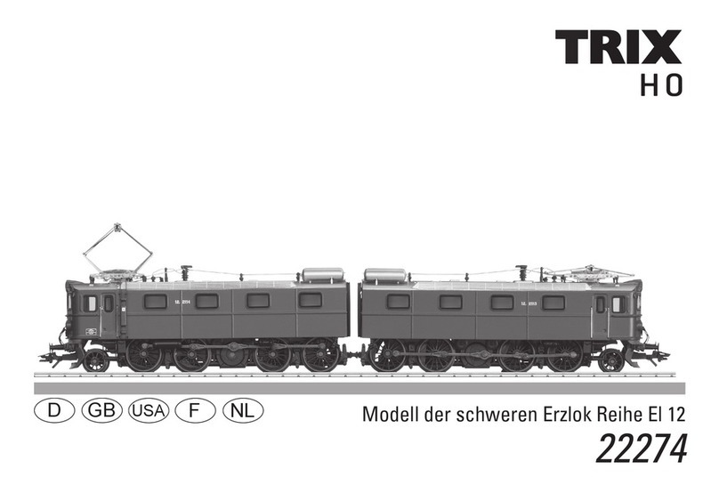
Trix Elektrolok Baureihe TRAXX 2 E 186 22165 User manual

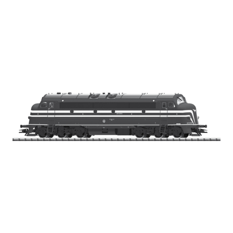
Modell der Elektrolok Baureihe TRAXX 2 E 186
22165
F
D GB USA NL

2

3
Inhaltsverzeichnis: Seite
Informationen zum Vorbild 4
Sicherheitshinweise 6
Wichtige Hinweise 6
Multiprotokollbetrieb 6
Schaltbare Funktionen 9
Parameter/Register 10
Wartung und Instandhaltung 26
Ersatzteile 30
Table of Contents: Page
Information about the prototype 4
Safety Notes 11
Important Notes 11
Multi-Protocol Operation 11
Controllable Functions 14
Parameter/Register 15
Service and maintenance 26
Spare Parts 30
Sommaire : Page
Informations concernant la locomotive réelle 5
Remarques importantes sur la sécurité 16
Information importante 16
Mode multiprotocole 16
Fonctions commutables 19
Paramètre/Registre 20
Entretien et maintien 26
Pièces de rechange 30
Inhoudsopgave: Pagina
Informatie van het voorbeeld 5
Veiligheidsvoorschriften 21
Belangrijke aanwijzing 21
Multiprotocolbedrijf 21
Schakelbare functies 24
Parameter/Register 25
Onderhoud en handhaving 26
Onderdelen 30

4
Informationen zum Vorbild
1994 erschien die AEG-Versuchslokomotive 12X, die fortan
als 128 001 bei der DB in Erprobung war. Die gewonnenen
Erkenntnisse flossen in die Entwicklung der Baureihe 145.
Die eigentliche Erfolgsgeschichte begann jedoch im Jahr
2000. Bombardier stellte die Mehrsystemvariante vor: Die
BR 185 war auch für die Stromsysteme der benachbar-
ten Bahnverwaltungen ausgelegt. Insgesamt sollen 400
Maschinen der Baureihe 185 beschafft werden. Je nach
Einsatzland werden die Loks mit den entsprechenden
Zugsicherungssystemen und elektrischen Ausrüstungen
„als Paket“ ausgestattet. So gibt es Loks mit zwei oder vier
Stromabnehmern und unterschiedlicher Schleifstückbreite
als augenscheinlichste äußere Unterschiede. Auch von der
Baureihe 185.1 gibt es viele Lokomotiven bei den privaten
Eisenbahnverkehrsunternehmen. Auch von dieser Version
gibt es eine 160 km/h schnelle Ausführung für den Nahver-
kehr als BR 146.1.
Die nächste Evolutionsstufe bilden die ab 2005 ausgelie-
ferten Lokomotiven der TRAXX-Familie auf europäischen
Schienen: Sie bekamen einen crashoptimierten Lokkasten,
der von vorne die Kontur der Lokomotive kraftvoller und
bulliger erscheinen läßt. Andere Änderungen betreffen die
elektrische Umrichteranlage. Nun als Baureihe 185.2 be-
zeichnet, stellt Railion im Augenblick 200 dieser Lokomotiven
in Dienst. Auch hiervon gibt es eine Nahverkehrsversion für
160 km/h, die Baureihe 146.2. Zur Zeit werden diese Lokomo-
tiven vor modernsten Doppelstockzügen im Raum Stuttgart,
Freiburg und Nürnberg eingesetzt.
Information about the prototype
In 1994, the AEG experimental 12X locomotive appeared,
which then underwent testing as road no. 128 001 on the DB.
The knowledge gained from this went into the development
of the class 145.
The real success story began in 2000 however. Bombardier
introduced the multiple system version: The class 185 was
also designed for the power current systems of neighbo-
ring railroads. A total of 400 units of the class 185 are to be
purchased. Depending on the country they will be used in,
the locomotives are being equipped with the correct train
safety systems and with electrical equipment as a “packa-
ge“. So, there are locomotives with two or four pantographs
and different contact wiper widths as the most noticeable
external difference. There are also many class 185.1
locomotives on private railroads. And, there is a class 146.1
160 km/h / 100 mph fast version of this locomotive for
commuter service.
The TRAXX family locomotives delivered starting in 2005
formed the next evolutionary step on European railroads:
They were equipped with locomotive bodies with improved
ability to withstand crashes; the shape of these locomotive
bodies looks more powerful and brawnier at the ends. Other
changes have to do with the electrical rectifier layout. Raili-
on is presently putting 200 of these locomotives into service
as the class 185.2. There is also a commuter service version
of this locomotive for 160 km/h / 100 mph, the class 146.2.
These locomotives are currently being used as motive
power for the latest bi-level trains in the areas of Stuttgart,
Freiburg, and Nuremberg.

5
Informations concernant le modèle réel
En 1994 apparut la locomotive d‘essai 12X d‘AEG, dès lors
testée par la DB sous l‘immatriculation 128 001. Les résultats
obtenus furent exploités pour la conception de la série 145.
La véritable «success-story» débuta toutefois en l‘an 2000
lorsque Bombardier présenta la variante polycourant : La
BR 185 était conçue aussi pour les systèmes de courant des
administrations ferroviaires voisines. Au total, 400 machines
de la série 185 doivent être acquises. En fonction du pays
d‘utilisation, les locomotives sont équipées d‘un «pack»
comprenant le système d‘arrêt d‘urgence et les équipe-
ments électriques adéquats. Extérieurement, les locomo-
tives se distinguent donc essentiellement par le nombre
de pantographes (deux ou quatre) et la largeur de leurs
semelles d‘archet. La série 185.1 est elle aussi très repré-
sentée sur les chemins de fer privés. Il existe également une
version rapide à 160 km/h de cette variante pour le trafic à
petite distance, désignée comme BR 146.1.
Les locomotives de la famille TRAXX livrées à partir de 2005
sur les rails européens représentent l‘étape d‘évolution su-
ivante : elles étaient équipées d‘une superstructure particu-
lièrement résistante en cas de collision leur conférant une
allure plus puissante et plus massive. D‘autres modifications
concernent le convertisseur électrique. Railion utilise actu-
ellement 200 de ces locomotives désormais immatriculées
dans la série 185.2. Là encore, il existe une version à 160
km/h pour le trafic à petite distance, la série 146.2.
Actuellement, ces locomotives sont utilisées pour remor-
quer les trains à deux niveaux les plus modernes dans la
région de Stuttgart, Fribourg et Nuremberg.
Informatie over het voorbeeld
In 1994 verscheen de AEG-proeflocomotief 12X, die voortaan
als 128 001 bij de DB op proef was. De opgedane ervaringen
vloeiden in de ontwikkeling van de serie 145.
De eigenlijke succesgeschiedenis begon echter in 2000.
Bombardier stelde de meersysteemvariant voor: de BR 185
was ook voor de stroomsystemen van de aangrenzende
spoorwegmaatschappijen ontworpen. In totaal worden 400
machines van de serie 185 aangeschaft. Al naar land van
inzet worden de locs met de desbetreffende treinbevei-
ligingssystemen en elektrische uitrustingen “als pakket“
uitgevoerd. Zo zijn er locs met twee of vier stroomafnemers
en verschillende breedtes sleepstukken als opvallendste
uiterlijke verschillen. Ook van de serie 185.1 zijn er veel
locomotieven bij de private spoorwegondernemingen. Ook
van deze versie is er een 160 km/h snelle uitvoering voor het
buurtverkeer als BR 146.1.
De volgende evolutiestap vormen de vanaf 2005 geleverde
locomotieven uit de TRAXX-familie op Europese rails: ze
kregen een loc-bak die optimaal crash-bestendig is, die
van voren de contouren van de locomotief krachtiger en
stoerder laat schijnen. Meer veranderingen betreffen de
elektrische omrichterinstallatie. Nu als serie 185.2 aangedu-
id stelt Railion op dit moment 200 van deze locomotieven in
dienst. Ook hiervan is er een versie voor buurtverkeer voor
160 km/h, de serie 146.2. Momenteel worden deze locomo-
tieven voor de modernste Dubbeldekstreinen in de regio‘s
Stuttgart, Freiburg en Nuerenberg ingezet.
6
Sicherheitshinweise
• DieLokdarfnurmiteinemdafürbestimmtenBetriebssys-
tem eingesetzt werden.
• Analogmax.15Volt=,digitalmax.22Volt~.
• DieLokdarfnurauseinerLeistungsquelleversorgt
werden.
• BeachtenSieunbedingtdieSicherheitshinweiseinder
Bedienungsanleitung zu Ihrem Betriebssystem.
• FürdenkonventionellenBetriebderLokmussdasAn-
schlussgleis entstört werden. Dazu ist das Entstörset
611 655 zu verwenden. Für Digitalbetrieb ist das Entstör-
set nicht geeignet.
• ACHTUNG! Funktionsbedingte scharfe Kanten und Spitzen.
• SetzenSiedasModellkeinerdirektenSonneneinstrah-
lung, starken Temperaturschwankungen oder hoher
Luftfeuchtigkeit aus.
• VerbauteLED`sentsprechenderLaserklasse1nach
Norm EN 60825-1.
Wichtige Hinweise
• DieBedienungsanleitungunddieVerpackungsind
Bestandteile des Produktes und müssen deshalb aufbe-
wahrt sowie bei Weitergabe des Produktes mitgegeben
werden.
• FürReparaturenoderErsatzteilewendenSiesichbittean
Ihren Trix-Fachhändler.
• GewährleistungundGarantiegemäßderbeiliegenden
Garantieurkunde.
• Entsorgung:www.maerklin.com/en/imprint.html
• DervolleFunktionsumfangistnurunterTrixSystems,
DCC und unter mfx verfügbar.
• Eingebaute,fahrtrichtungsabhängigeStirnbeleuchtung.
Im Digitalbetrieb schaltbar.
• BefahrbarerMindestradius360mm.
Multiprotokollbetrieb
Analogbetrieb
Der Decoder kann auch auf analogen Anlagen oder Gleis-
abschnitten betrieben werden. Der Decoder erkennt die
analoge Gleichspannung (DC) automatisch und passt sich
der analogen Gleisspannung an. Es sind alle Funktionen,
die unter mfx oder DCC für den Analogbetrieb eingestellt
wurden aktiv (siehe Digitalbetrieb).
Digitalbetrieb
Der Decoder ist ein Multiprotokolldecoder. Der Decoder
kann unter folgenden Digital-Protokollen eingesetzt werden:
mfx oder DCC.
Das Digital-Protokoll mit den meisten Möglichkeiten ist das
höchstwertige Digital-Protokoll. Die Reihenfolge der Digital-
Protokolle ist in der Wertung fallend:
Priorität 1: mfx
Priorität 2: DCC
Priorität 3: DC
Hinweis: Werden zwei oder mehrere Digital-Protokolle am
Gleis erkannt, übernimmt der Decoder automatisch das
höchstwertige Digital-Protokoll; z.B. wird mfx & DCC erkannt
wird das mfx-Digital-Protokoll vom Decoder übernommen.

7
Hinweis: Beachten Sie, dass nicht alle Funktionen in allen
Digital-Protokollen möglich sind. Unter mfx und DCC können
einige Einstellungen von Funktionen, welche im Analog-
Betrieb wirksam sein sollen, vorgenommen werden.
Hinweise zum Digitalbetrieb
• DiegenaueVorgehensweisezumEinstellenderdiversen
Parameter entnehmen Sie bitte der Bedienungsanleitung
Ihrer Mehrzug-Zentrale.
• DieabWerkeingestelltenWertesindfürmfxgewählt,so
dass ein bestmöglichstes Fahrverhalten gewährleistet ist.
Für andere Betriebssysteme müssen gegebenenfalls
Anpassungen getätigt werden.
• DerBetriebmitgegenpoligerGleichspannungim
Bremsabschnitt ist mit der werkseitigen Einstellung
nicht möglich. Ist diese Eigenschaft gewünscht, so muss
auf den konventionellen Gleichstrombetrieb verzichtet
werden(CV29/Bit2=0).
mfx-Protokoll
Adressierung
• KeineAdresseerforderlich,jederDecodererhälteine
einmalige und eindeutige Kennung (UID).
• DerDecodermeldetsichaneinerCentralStationoder
Mobile Station mit seiner UID automatisch an.
• NameabWerk:E186 184-8 SNCF
Programmierung
• DieEigenschaftenkönnenüberdiegrascheOberäche
der Central Station bzw. teilweise auch mit der Mobile
Station programmiert werden.
• EskönnenalleCongurationVariablen(CV)mehrfach
gelesen und programmiert werden.
• DieProgrammierungkannentwederaufdemHaupt-oder
dem Programmiergleis erfolgen.
• DieDefaulteinstellungen(Werkseinstellungen)können
wieder hergestellt werden.
• Funktionsmapping:FunktionenkönnenmitHilfeder
Central Station 60212 (eingeschränkt) und mit der Central
Station 60213/60214/60215 beliebigen Funktionstasten
zugeordnet werden (siehe Hilfe in der Central Station).

8
DCC-Protokoll
Adressierung
• MöglicheAdressen:Kurze,langeundTraktionsadresse
• Adressbereich:
1 – 127 (kurze Adresse, Traktionsadresse)
1 – 10239 (lange Adresse)
• JedeAdresseistmanuellprogrammierbar.
• KurzeoderlangeAdressewirdüberdieCVsausgewählt.
• EineangewandteTraktionsadressedeaktiviertdie
Standard-Adresse.
Programmierung
• DieEigenschaftenkönnenüberdieCongurationsVari-
ablen (CV) mehrfach geändert werden.
• DieCV-NummerunddieCV-Wertewerdendirekteinge-
geben.
• DieCVskönnenmehrfachgelesenundprogrammiert
werden (Programmierung auf dem Programmiergleis).
• DieCVskönnenbeliebigprogrammiertwerden.PoM
(Programmierung auf dem Hauptgleis PoM) ist nur bei
den in der CV-Tabelle gekennzeichneten CV möglich.
PoM muss von Ihrer Zentrale unterstützt werden (siehe
Bedienungsanleitung ihres Gerätes).
• DieDefaulteinstellungen(Werkseinstellungen)können
wieder hergestellt werden.
• 14bzw.28/126Fahrstufeneinstellbar.
• AlleFunktionenkönnenentsprechenddemFunktions-
mapping geschaltet werden.
• WeitereInformation,sieheCV-TabelleDCC-Protokoll.
Es wird empfohlen, die Programmierungen grundsätzlich auf
dem Programmiergleis vorzunehmen.
Logische Funktionen
Anfahr-/Bremsverzögerung
• DieBeschleunigungs-undBremszeitkönnengetrennt
von einander eingestellt werden.
• DielogischeFunktionsabschaltungABVkannüberdas
Funktionsmapping auf jede beliebige Funktionstaste
gelegt werden.

9
Schaltbare Funktionen
Spitzensignal / Schlusslicht rot an Funktion f0 Funktion f0
Geräusch: Ankuppeln (Puffer an Puffer) — Funktion 1 Funktion f1 Funktion f1
Fahrgeräusch — Funktion 2 Funktion f2 Funktion f2
Geräusch: Signalhorn — Funktion 3 Funktion f3 Funktion f3
ABV aus — Funktion 4 Funktion f4 Funktion f4
Geräusch: Bremsenquietschen aus — Funktion 5 Funktion f5 Funktion f5
Spitzensignal Führerstand 2 aus — + 6 f0 + f6 f0 + f6
Geräusch: Rangierpfiff — Funktion 7 Funktion f7 Funktion f7
Spitzensignal Führerstand 1 aus — + 8 f0 + f8 f0 + f8
Geräusch: Ankuppeln — — Funktion f9 Funktion f9
Geräusch: Abkuppeln — — Funktion f10 Funktion f10
Geräusch: Druckluft ablassen — — Funktion f11 Funktion f11
Geräusch: Lüfter — — Funktion f12 Funktion f12
Geräusch: Schaffnerpfiff — — Funktion f13 Funktion f13
Geräusch: Sanden — — Funktion f14 Funktion f14
Rangierlicht doppel A — + 6 + 8 f0 +f6 + f8 f0 + f6 + f8
STOP mobile station
15
f0 f8 f0f8
f0 - f3 f4 - f7

10
CV Bedeutung Wert DCC ab Werk
1 Adresse 1 - 127 3
2 PoM Minimalgeschwindigkeit 0 - 255 3
3 PoM Anfahrverzögerung 0 - 255 12
4 PoM Bremsverzögerung 0 - 255 12
5 PoM Maximalgeschwindigkeit 0 - 255 245
8 Werkreset/Herstellerkennung 8 131
13 PoM Funktionen F1 - F8 im Analogbetrieb 0 - 255 0
14 PoM Funktionen F9 - F15 und Licht im Analogbetrieb 0 - 255 1
17 Erweiterte Adresse (oberer Teil) CV29,Bit5=1 192
18 Erweiterte Adresse (unterer Teil) CV29,Bit5=1 128
19 Traktionsadresse 0 - 255 0
21 PoM Funktionen F1 - F8 bei Traktion 0 - 255 0
22 PoM Funktionen F9 - F15 und Licht bei Traktion 0 - 255 0
29 PoM
Bit 0: Umpolung Fahrtrichtung
Bit 1: Anzahl Fahrstufen 14 oder 28/128*
Bit 2: DCC Betrieb mit Bremsstrecke (kein Analogbetrieb möglich)
Bit 5: kurze / lange Adresse
0 / 1
0 / 2
0 / 4
0 / 32
0, 1, 2, 3, 4, 5, 6,
7, 32, 34, 35, 36,
37, 38, 39 6
63 PoM Lautstärke 0 - 255 255
* Fahrstufen am Lokdecoder und am Steuergerät müssen übereinstimmen, es sind sonst Fehlfunktionen möglich.

11
Systems and under DCC and mfx.
• Built-inheadlightsthatchangeoverwiththedirectionof
travel. They can be turned on and off in digital operation.
• Minimumradiusforoperationis360mm/14-3/16“.
Multi-Protocol Operation
Analog Operation
This decoder can also be operated on analog layouts or ar-
eas of track that are analog. The decoder recognizes alter-
nating current (DC) and automatically adapts to the analog
track voltage. All functions that were set under mfx or DCC
for analog operation are active (see Digital Operation).
Digital Operation
The decoders are multi-protocol decoders. These decoders
can be used under the following digital protocols: mfx or DCC.
The digital protocol with the most possibilities is the highest
order digital protocol. The sequence of digital protocols in
descending order is:
Priority 1: mfx
Priority 2: DCC
Priority 3: DC
Note: Please note that not all functions are possible in all
digital protocols. Several settings for functions, which are
supposed to be active in analog operation, can be done
under mfx and DCC.
Note: If two or more digital protocols are recognized in the
track, the decoder automatically takes on the highest value
digital protocol.For example, if mfx & DCC are recognized,
the mfx digital protocol is taken on by the decoder.
Safety Notes
• Thislocomotiveisonlytobeusedwiththeoperating
system it is designed for.
• Analogmax.15voltsDC,digitalmax.22voltsAC.
• Thislocomotivemustneverbesuppliedwithpowerfrom
more than one power pack.
• Pleasemakenoteofthesafetynotesintheinstructions
for your operating system.
• Thefeedertrackmustbeequippedtopreventinter-
ference with radio and television reception, when the
locomotive is to be run in conventional operation. The
611 655 interference suppression set is to be used for this
purpose. The interference suppression set is not suitable
for digital operation.
• WARNING! Sharp edges and points required for operation.
• Donotexposethemodeltodirectsunlight,extreme
changes in temperature, or high humidity.
• TheLEDsinthisitemcorrespondtoLaserClass1accor-
ding to Standard EN 60825-1.
Important Notes
• Theoperatinginstructionsandthepackagingareacom-
ponent part of the product and must therefore be kept as
well as transferred along with the product to others.
• PleaseseeyourauthorizedTrixdealerforrepairsor
spare parts.
• Thewarrantycardincludedwiththisproductspecies
the warranty conditions.
• Disposing:www.maerklin.com/en/imprint.html
• ThefullrangeoffunctionsisonlyavailableunderTrix

12
Notes on digital operation
• Theoperatinginstructionsforyourcentralunitwillgive
you exact procedures for setting the different parame-
ters.
• Thevaluessetatthefactoryhavebeenselectedformfx
in order to guarantee the best possible running characte-
ristics.
Adjustments may have to be made for other operating
systems.
• Thesettingdoneatthefactorydoesnotpermitoperation
with opposite polarity DC power in the braking block.
If you want this characteristic, you must do without
conventionalDCpoweroperation(CV29/Bit2=0).
mfx Protocol
Addresses
• Noaddressisrequired;eachdecoderisgivenaone-
time, unique identifier (UID).
• ThedecoderautomaticallyregistersitselfonaCentral
Station or a Mobile Station with its UID.
• Namesetatthefactory:E186 184-8 SNCF
Programming
• Thecharacteristicscanbeprogrammedusingthe
graphic screen on the Central Station or also partially
with the Mobile Station.
• AlloftheCongurationVariables(CV)canbereadand
programmed repeatedly.
• Theprogrammingcanbedoneeitheronthemaintrackor
the programming track.
• Thedefaultsettings(factorysettings)canbeproduced
repeatedly.
• Functionmapping:Functionscanbeassignedtoanyof
the function buttons with the help of the 60212 Central
Station (with limitations) and with the 60213/60214/60215
Central Station (See help section in the Central Station).

13
DCC Protocol
Addresses
• Possibleaddresses:short,long,andm.u.address
• Addressrange:
1 – 127 (short address, m.u. address)
1 – 10239 (long address)
• Everyaddresscanbeprogrammedmanually.
• AshortoralongaddressisselectedusingtheCVs.
• Amultipleunitaddressthatisbeinguseddeactivatesthe
standard address.
Programming
• Thecharacteristicscanbechangedrepeatedlyusingthe
Configuration Variables (CV).
• TheCVnumbersandtheCVvaluesareentereddirectly.
• TheCVscanbereadandprogrammedrepeatedly.(Pro-
gramming is done on the programming track.)
• TheCVscanbeprogrammed,asyoudesire.PoM(Pro-
gramming on the layout track) is only possible with those
CVs marked in the CV table. PoM must be supported
by your central controller (see the instructions for your
controller).
• Thedefaultsettings(factorysettings)canbeproduced
repeatedly.
• 14or28/126speedlevelscanbeset.
• Allofthefunctionscanbecontrolledaccordingtothe
function mapping (see CV description).
• SeetheCVdescriptionfortheDCCprotocolforadditional
information.
We recommend that in general programming should be
done on the programming track.
Logic Functions
Acceleration / Braking Delay
• Theaccelerationandbrakingtimescanbesetseparately
from each other.
• ThelogicalfunctionshutoffforABV(Acceleration/
Braking Delay) can be assigned to any function button by
means of function mapping.

14
Controllable Functions
Headlights / Red marker light on Function f0 Function f0
Sound effect: coupling together (buffer to buffer) — Function 1 Function f1 Function f1
Locomotive operating sounds — Function 2 Function f2 Function f2
Sound effect: Horn — Function 3 Function f3 Function f3
ABV off — Function 4 Function f4 Function f4
Sound effect: Squealing brakes off — Function 5 Function f5 Function f5
Headlights Engineer‘s Cab 2 off — + 6 f0 + f6 f0 + f6
Sound effect: Switching whistle — Function 7 Function f7 Function f7
Headlights Engineer‘s Cab 1 off — + 8 f0 + f8 f0 + f8
Sound effect: coupling — — Function f9 Function f9
Sound effect: uncoupling — — Function f10 Function f10
Sound effect: Letting off air — — Function f11 Function f11
Sound effect: Blower — — Function f12 Function f12
Sound effect: Conductor whistle — — Function f13 Function f13
Sound effect: Sanding — — Function f14 Function f14
Double A switching light — + 6 + 8 f0 + f6 + f8 f0 + f6 + f8
STOP mobile station
15
f0 f8 f0f8
f0 - f3 f4 - f7

15
* The speed levels on the locomotive decoder and on the controller must agree with each other; otherwise,
you may have malfunctions.
CV Discription DCC Value Factory-Set
1 Address 1 - 127 3
2 PoM Minimum Speed 0 - 255 3
3 PoM Acceleration delay 0 - 255 12
4 PoM Braking delay 0 - 255 12
5 PoM Maximum speed 0 - 255 245
8 Factory Reset / Manufacturer Recognition 8 131
13 PoM Functions F1 - F8 in analog operation 0 - 255 0
14 PoM Functions F9 - F15 and lights in analog operation 0 - 255 1
17 Extended address (upper part) CV29,Bit5=1 192
18 Extended address (lower part) CV29,Bit5=1 128
19 Multiple Unit Address 0 - 255 0
21 PoM Functions F1 - F8 on Multiple Unit 0 - 255 0
22 PoM Functions F9 - F15 and lights on Multiple Unit 0 - 255 0
29 PoM
Bit 0: Reversing direction of travel
Bit 1: Number of speed levels 14 or 28/128*
Bit 2: DCC operation with a braking area (no analog operation
possible)
Bit 5: short / long address
0 / 1
0 / 2
0 / 4
0 / 32
0, 1, 2, 3, 4, 5, 6,
7, 32, 34, 35, 36,
37, 38, 39 6
63 PoM Volume 0 - 255 255

16
Remarques importantes sur la sécurité
• Lalocomotivenepeutêtreutiliséequ‘aveclesystème
d‘exploitation indiqué.
• Analogiquemax.15Volt=,digitalmax.22Volt~.
• Lalocomotivenepeutpasêtrealimentéeélectriquement
par plus d‘une source de courant à la fois.
• Ilestimpératifdetenircomptedesremarquessurla
sécurité décrites dans le mode d‘emploi de votre système
d‘exploitation.
•
Pour l’exploitation de la locomotive en mode convention-
nel, la voie de raccordement doit être déparasitée. A cet
effet, utiliser le set de déparasitage réf. 611 655. Le set de
déparasitage ne convient pas pour l’exploitation en mode
numérique.
•
ATTENTION! Pointes et bords coupants lors du fonctionne-
ment du produit.
• Nepasexposerlemodèleàunensoleillementdirect,
à de fortes variations de température ou à un taux
d‘humidité important.
• LesDELinstalléescorrespondentàlaclasselaser1
selon la norme EN 60825-1.
Information importante
• Lanoticed‘utilisationetl’emballagefontpartieintégrante
du produit ; ils doivent donc être conservés et, le cas
échéant, transmis avec le produit.
• Pourtouteréparationouremplacementdepièces,adres-
sez vous à votre détaillant-spécialiste Trix.
• Garantielégaleetgarantiecontractuelleconformément
au certificat de garantie ci-joint.
• Elimination:www.maerklin.com/en/imprint.html
• L’intégralitédesfonctionsestdisponibleuniquementen
exploitation Trix Systems, DCC et mfx.
• Feuxdesignalisations‘inversantselonlesensdemar-
che; feux commutables en exploitation digital.
• Rayonminimald’inscriptionencourbe360mm.
Mode multiprotocole
Mode analogique
On peut aussi faire fonctionner le décodeur sur des instal-
lations ou des sections de voie analogiques. Le décodeur
identifie automatiquement la tension de voie analogique
(DC). Toutes les fonctions qui ont été paramétrée pour le
mode analogique sous mfx ou sous DCC sont actives (voir
mode numérique).
Mode numérique
Les décodeur sont des décodeur multiprotocole. Le
décodeur peut être utilisé avec les protocoles numériques
suivants : mfx, DCC
Le protocole numérique offrant les possibilités les plus
nombreuses est le protocole numérique à bit de poids
fort. La hiérarchisation des protocoles numériques est
descendante :
Priorité 1 : mfx
Priorité 2 : DCC
Priorité 3 : DC
Indication : Si deux ou plus de deux protocoles numériques
sont reconnus sur la voie, le décodeur choisit automatique-
ment le protocole numérique le plus significatif. Entre les

17
protocoles mfx & DCC par exemple, le décodeur choisira le
protocole numérique mfx.
Indication : remarquez que toutes les fonctions ne peuvent
pas être actionnées dans tous les protocoles numériques.
Sous mfx et sous DCC, il est possible de procéder à
quelques paramétrages de fonctions devant être actives
dans le cadre de l’exploitation analogique.
Remarques relatives au fonctionnement en mode digital
• Encequiconcernelaprocédurederéglagedesdivers
paramètres, veuillez vous référer au mode d‘emploi de
votre centrale de commande multitrain.
• Lesvaleursparamétréesd’usinesontchoisiespour
mfx de manière à garantir le meilleur comportement de
roulement possible.
Pour d’autres systèmes d’exploitation, ces valeurs dev-
ront éventuellement être adaptées.
• L’exploitationaveccourantcontinudepolaritéinverse
dans les sections de freinage n’est pas possible avec
le réglage d’usine. Si cette propriété est désirée, il faut
alors renoncer à l’exploitation conventionnelle en cou-
rantcontinu(CV29/Bit2=0).
Protocole mfx
Adressage
• Aucuneadressen’estnécessaire,ledécodeurreçoittou-
tefois une identification unique et non équivoque (UID).
• AvecsonUID,ledécodeurindiqueautomatiquement
à une station centrale ou à une station mobile qu’il est
connecté.
• Nomencodeeenusine:E186 184-8 SNCF
Programmation
• Lescaractéristiquespeuventêtreprogramméespar
l’intermédiaire de la couche graphique de la station cen-
trale, voire en partie aussi au moyen de la station mobile.
• Touteslescongurationsvariables(CV)peuventêtrelues
et programmées de façon réitérée.
• Laprogrammationpeutêtreréaliséesoitsurlavoie
principale, soit sur la voie de programmation.
• Lesparamétragespardéfaut(paramétragesusine)
peuvent être rétablis.
• Mappagedesfonctions:lesfonctionspeuventêtre
affectées à de quelconques touches de fonction au
moyen de la station centrale (60212) (restreinte) et avec
la station centrale 60213/60214/60215 (voir Aide au niveau
de la station centrale).

18
Protocole DCC
Adressage
• Adressepossibles:Courtes,longuesetadressesdetraction
• Catégoried’adresse:
1 à 127 (adresses courtes, adresses de traction)
1 à 10239 (adresses longues)
• Chaqueadresseestprogrammablemanuellement.
• L’adressebrèveoulongueestchoisieparl’intermédiaire
des CVs.
• Uneadressedetractionutiliséedésactivel’adresse
standard.
Programmation
• Lescaractéristiquespeuventêtremodiéesdefaçon
réitérée par l’intermédiaire des variables de configuration
(CVs).
• Touteslescongurationsvariables(CV)peuventêtrelues
et programmées de façon réitérée.
• Laprogrammationpeutêtreréaliséesoitsurlavoie
principale, soit sur la voie de programmation.
• LesCVpeuventêtreprogramméeslibrement.LaPoM
(programmation sur la voie principale) est possible
uniquement pour les CV signalées dans le tableau des CV.
La PoM doit être prise en charge par votre centrale (voir
la notice d’utilisation de votre appareil).
• Lesparamétragespardéfaut(paramétragesusine)
peuvent être rétablis.
• 14voire28/126cransdemarchesontparamétrables.
• Touteslesfonctionspeuventêtrecommutéesenfonction
du mappage des fonctions (voir le descriptif des CVs).
• Pourtouteinformationcomplémentaire,voirletableau
des CVs, protocole DCC.
Il est recommandé, de réaliser la programmation, fonda-
mentalement, sur la voie de programmation.
Fonctions logiques
Temporisation d’accélération et de freinage (TAF)
• Lestempsd’accélérationetdefreinagepeuventêtre
définis indépendamment l’un de l’autre.
• LadésactivationdelafonctionlogiqueTAFpeutêtre
affectée à n’importe quelle touche de fonction via le
mappage de fonctions.

19
Fonctions commutables
Fanal / Feu de fin de convoi rouge activé Fonction f0 Fonction f0
Bruitage : Attelage (tampons joints) — Fonction 1 Fonction f1 Fonction f1
Bruit de roulement — Fonction 2 Fonction f2 Fonction f2
Bruitage : trompe, signal — Fonction 3 Fonction f3 Fonction f3
ABV, désactivé — Fonction 4 Fonction f4 Fonction f4
Bruitage : Grincement de freins désactivé — Fonction 5 Fonction f5 Fonction f5
Fanal cabine de conduite 2 éteint — + 6 f0 + f6 f0 + f6
Bruitage : Sifflet pour manœuvre — Fonction 7 Fonction f7 Fonction f7
Fanal cabine de conduite 1 éteint — + 8 f0 + f8 f0 + f8
Bruitage Attelage — — Fonction f9 Fonction f9
Bruitage Déconnecter — — Fonction f10 Fonction f10
Bruitage : Échappement de l‘air comprimé — — Fonction f11 Fonction f11
Bruitage : ventilateur — — Fonction f12 Fonction f12
Bruitage : Sifflet Contrôleur — — Fonction f13 Fonction f13
Bruitage : Sablage — — Fonction f14 Fonction f14
Feu de manœuvre double A — + 6 + 8 f0 + f6 + f8 f0 + f6 + f8
STOP mobile station
15
f0 f8 f0f8
f0 - f3 f4 - f7

20
CV Affectation DCC Valeur Parm. Usine
1 Adresse 1 - 127 3
2 PoM Vitesse minimale 0 - 255 3
3 PoM Temporisation d‘accélération 0 - 255 12
4 PoM Temporisation de freinage 0 - 255 12
5 PoM Vitesse maximale 0 - 255 245
8 Réinitialisation d’usine/identification du fabricant 8 131
13 PoM Fonctions F1 - F8 en mode analogique 0 - 255 0
14 PoM Fonctions F9 - F15 et éclairage en mode analogique 0 - 255 1
17 Adresse étendue (partie supérieure) CV29,Bit5=1 192
18 Adresse étendue (partie inférieure) CV29,Bit5=1 128
19 Adresse traction 0 - 255 0
21 PoM Fonctions F1 - F8 pour traction 0 - 255 0
22 PoM Fonctions F9 - F15 et éclairage traction 0 - 255 0
29 PoM
Bit 0 : Inversion du sens de marche
Bit 1: Nombre de crans de marche 14 ou 28/128*
Bit 2: Exploitation DCC avec section de freinage (exploitation
analogique impossible)
Bit 5: Adresse courte/longue
0 / 1
0 / 2
0 / 4
0 / 32
0, 1, 2, 3, 4, 5, 6,
7, 32, 34, 35, 36,
37, 38, 39 6
63 PoM Volume 0 - 255 255
* Pour éviter tout dysfonctionnement, les crans de marche sur le décodeur de loco doivent impérativement
coïncider avec ceux de l’appareil de commande.
Table of contents
Languages:
Other Trix Toy manuals
Popular Toy manuals by other brands

Art-Tech
Art-Tech F6F Hellcat instruction manual

Real Cooking
Real Cooking Ultimate Baking instruction manual

beeloom
beeloom my little business instruction manual

Fisher-Price
Fisher-Price GO DIEGO GO K6673 user manual

E-BLOX
E-BLOX CIRCUIT BLOX Burp 'n Fart Machine instructions

LEGO
LEGO CREATOR 31058 instructions