Trix H0 BR 96 User manual

Modell der Dampflok BR 96
22059

2
Inhaltsverzeichnis: Seite
Informationen zum Vorbild 4
Sicherheitshinweise 6
Wichtige Hinweise 6
Funktionen 6
Schaltbare Funktionen 7
CVs und Parameter 8
Ergänzendes Zubehör 30
Wartung und Instandhaltung 31
Ersatzteile 38
Table of Contents: Page
Information about the prototype 4
Safety Notes 9
Important Notes 9
Functions 9
Controllable Functions 10
CVs and Parameters 11
Complementary accessories 30
Service and maintenance 31
Spare Parts 38
Sommaire : Page
Informations concernant la locomotive réelle 5
Remarques importantes sur la sécurité 12
Information importante 12
Fonctionnement 12
Fonctions commutables 13
CVs et paramètres 14
Accessoires complémentaires 30
Entretien et maintien 31
Pièces de rechange 38
Inhoudsopgave: Pagina
Informatie van het voorbeeld 5
Veiligheidsvoorschriften 14
Belangrijke aanwijzing 14
Functies 14
Schakelbare functies 15
CV’s en parameter 16
Aanvullende toebehoren 30
Onderhoud en handhaving 31
Onderdelen 38

3
Indice de contenido: Página
Aviso de seguridad 18
Notas importantes 18
Funciones 18
Funciones posibles 19
CVs y parámetros 20
Accesorios complementarios 30
El mantenimiento 31
Recambios 38
Indice del contenuto: Pagina
Avvertenze per la sicurezza 21
Avvertenze importanti 21
Funzioni 21
Funzioni commutabili 22
CV e parametri 23
Accessori complementari 30
Manutenzione ed assistere 31
Pezzi di ricambio 38
Innehållsförteckning: Sida
Säkerhetsanvisningar 24
Viktig information 24
Funktioner 24
Kopplingsbara funktioner 25
CV och parametrar 26
Ytterligare tillbehör 30
Underhåll och reparation 31
Reservdelar 38
Indholdsfortegnelse: Side
Vink om sikkerhed 27
Vigtige bemærkninger 27
Funktioner 27
Styrbare funktioner 28
CV‘er og parametre 29
Ekstra tilbehør 30
Service og reparation 31
Reservedele 38

4
Information zum Vorbild
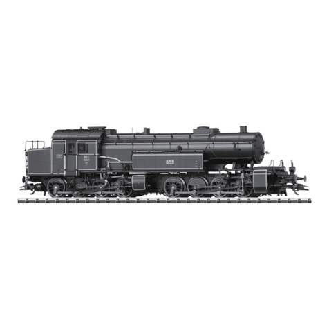
Auf drei Steilrampen im Bereich der Bayerischen Staatsbahn
waren Anfang dieses Jahrhunderts die eingesetzten Lokomoti-
ven den Anforderungen bezüglich der erforderlichen Zugleistung
nicht mehr gewachsen. Daher bekam die Firma Maffei den
Auftrag, eine leistungsfähige Tenderlok für diese Strecken zu
konstruieren und zu bauen.
Das Ergebnis war die Tenderlokomotive mit der Gattungsbe-
zeichnung Gt 2 x 4/4. Mit einer Länge über Puffer von 17 700 mm
und einer Leistung von 1.080 kW (1.470 PS) war diese Lok damals
die größte und leistungsfähigste Tenderlok Europas.
Damit die Vorgaben bezüglich maximaler Achslast von 15 t bei
gleichzeitigem großen Kessel eingehalten werden konnten, ent-
schied man sich bei Maffei für ein Triebwerk der Bauart Mallet,
wodurch trotz der großen Länge der Lok eine gute Kurventaug-
lichkeit gesichert war.
Die erste Lokbauserie wurde ab 1913 ausgeliefert. Ab 1922
wurde eine zweite Bauserie mit einer noch höheren Leistung
ausgeliefert. Alle Lokomotiven wurden als BR 96 im Güter- und
Personenverkehr eingesetzt. Einige Lokomotiven waren auch
nach 1945 noch in Bayern im Einsatz.
Information about the Prototype
At the start of this century the locomotives in use on three
steeply graded routes in the area administered by the Bava-
rian State Railroad could no longer meet the requirements
for powering trains over the routes. The Maffei Company was
therefore given an order to design and build a powerful tank
locomotive for these routes.
The result was the tank locomotive with the designation
Gt 2 x 4/4. With a length of 17,700 mm (approx. 58 feet) and an
output of 1,080 kilowatts (1,470 horsepower) this locomotive
was the largest and most powerful tank locomotive in Europe
at the time.
In order to keep the maximum axle load to 15 tons while
maintaining a large boiler as part of the design, it was decided
at Maffei to build a Mallet type of frame which insured that
the locomotive could negotiate sharp curves despite its great
length.
The first series was delivered in 1913. Starting in 1922 a se-
cond series with a still high power output was delivered. All of
these locomotives were taken over by the DRG and were used
as the class 96 in freight and passenger traffic. A few units
were still in use in Bavaria even after 1945.

5
Informations concernant la locomotive réelle
Les locomotives utilisées au début de ce siècle sur trois côtes
du réseau de Chemins de fer nationaux bavarois n’étaient plus
à même de satisfaire aux exigences en matière de puissance de
traction requises. C’est la raison pour laquelle la sociêté Maffei
fut chargée de développer et de construire une locomotive
tender puissante pour ces lignes.
Le résultat en fut la locomotive tender connue sous la dési-
gnation Gt 2 x 4/4. Avec une longueur hors tampons de 17 700
mm et une puissance de 1.080 kW (1.470 PS) cette locomotive
était alors la plus grande et la plus puissante locomotive tender
d’Europe.
Afin de repecter les instructions concernant la charge maximale
par essieu de 15 t, et ce malgré la grande chaudière, les ingéni-
eurs de Maffei optèrent pour un mécanisme de locomotion de
type Benart Mallet, qui permettait d’assurer une bonne tenue en
courbe, malgré la grande longueur de la locomotive.
La première série de locomotives fut livrée à partir de 1913.
Une deuxième série encore plus puissante fut livrée à partir de
1922. Toutes les locomotives furent reprises par la DRG et furent
utilisées dans le trafic de voyageurs et dans le trafic de ar-
chandises sous l’apellation BR 96. Quelques locomotives étaient
encore en service en Bavière près 1945.
Informatie van het voorbeeld
Op drie steile trajecten binnen het gebied van de Bayerische
Staatsbahn waren in het begin van deze eeuw de ingezette
locomotieven niet langer opgewassen tegen de gestelde eisen
wat betreft de treinvermogens. Daarom kreeg de firma Maffei
de opdracht een sterke tenderlok voor deze trajecten de ontwik-
kelen en te bouwen.
Het resultaat was de tenderlokomotief met de soortaanduiding
Gt 2 x 4/4. Met een lengte over buffers van 17 700 mm en een
vermogen van 1.080 kW (1.470 pk) was deze lok toentertijd de
grootste en sterkste tenderlok in Europa.
Om binnen de gestelde maten voor de asdruk (15 ton) en toch
met een grote ketel te kunnen blijven, besloot men bij Maffei
tot een drijfwerk volgens het systeem van Mallet, waardoor
ondanks de grote lengte van de lok toch een goede loop in
bogen verzekerd was.
De eerste lokserie werd vanaf 1913 afgeleverd. Vanaf 1922 werd
een tweede serie met een groter vermogen afgeleverd. Alle
lokomotieven werden door de DRG overgenomen en ze werden
als serie 96 in het goederen- en personenvervoer ingezt. Enkele
lokomotieven waren ook na 1945 nog in gebruik in Beieren.
6
Sicherheitshinweise
• DieLokdarfnurmiteinemdafürbestimmtenBetriebssystem
eingesetzt werden.
• Analogmax.15Volt=,digitalmax.22Volt~.
• DieLokdarfnurauseinerLeistungsquelleversorgtwerden.
• BeachtenSieunbedingtdieSicherheitshinweiseinder
Bedienungsanleitung zu Ihrem Betriebssystem.
• FürdenkonventionellenBetriebderLokmussdasAnschluss-
gleis entstört werden. Dazu ist das Entstörset
611 655 zu verwenden. Für Digitalbetrieb ist das Entstörset
nicht geeignet.
• ACHTUNG! Funktionsbedingte scharfe Kanten und Spitzen.
• SetzenSiedasModellkeinerdirektenSonneneinstrahlung,
starken Temperaturschwankungen oder hoher Luftfeuchtig-
keit aus.
Wichtige Hinweise
• DieBedienungsanleitungunddieVerpackungsindBestand-
teile des Produktes und müssen deshalb aufbewahrt sowie
bei Weitergabe des Produktes mitgegeben werden.
• FürReparaturenoderErsatzteilewendenSiesichbittean
Ihren Trix-Fachhändler.
• GewährleistungundGarantiegemäßderbeiliegendenGaran-
tieurkunde.
• http://www.maerklin.com/en/imprint.html
Funktionen
• EingebauteElektronikzumwahlweisenBetriebmitkonventio-
nellem Gleichstrom-Fahrgerät, Trix Systems oder Digitalsyste-
men nach NMRA-Norm.
• AutomatischeSystemerkennungzwischenDigital-und
Analog-Betrieb.
• DervolleFunktionsumfangistnurunterTrixSystemsund
unter DCC verfügbar.
• Eingebaute,fahrtrichtungsabhängigeStirnbeleuchtung.
Im Digitalbetrieb schaltbar.
• BefahrbarerMindestradius360mm.
Hinweise zum Digitalbetrieb
• DiegenaueVorgehensweisezumEinstellenderdiversen
Parameter entnehmen Sie bitte der Bedienungsanleitung
Ihrer Mehrzug-Zentrale.
• DieabWerkeingestelltenWertesindsogewählt,dass
bestmöglichstes Fahrverhalten gewährleistet ist.
• DerBetriebmitgegenpoligerGleichspannungimBremsab-
schnitt ist mit der werkseitigen Einstellung nicht möglich. Ist
diese Eigenschaft gewünscht, so muss auf den konventio-
nellenGleichstrombetriebverzichtetwerden(CV29/Bit2=0).

7
Schaltbare Funktionen
Stirnbeleuchtung an Funktion f0 Funktion f0
Geräusch:Betriebsgeräusch — Funktion 2 Funktion f2 Funktion f2
Geräusch:Lokpfeife — Funktion 3 Funktion f3 Funktion f3
ABV, aus — Funktion 4 Funktion f4 Funktion f4
Geräusch:Bremsenquietschenaus — Funktion 5 Funktion f5 Funktion f5
Geräusch:Kohleschaufeln — Funktion 6 Funktion f6 Funktion f6
Geräusch:Rangierpff — Funktion 7 Funktion f7 Funktion f7
Geräusch:Luftpumpe — Funktion 8 Funktion f8 Funktion f8
Geräusch:Injektor — — Funktion f9 Funktion f9
Geräusch:Dampfablassen — — Funktion f10 Funktion f10
Geräusch:Schüttelrost — — Funktion f11 Funktion f11
STOP mobile station
systems
15
f0 f8 f0f8
f0 - f3 f4 - f7

8
CV Bedeutung Wert DCC ab Werk
1 Adresse 1 - 127 3
2 PoM Minimalgeschwindigkeit 0 - 255 10
3 PoM Anfahrverzögerung 0 - 255 5
4 PoM Bremsverzögerung 0 - 255 3
5 PoM Maximalgeschwindigkeit 0 - 255 255
8 Werkreset/Herstellerkennung 8 131
13 PoM Funktionen F1 - F8 im Analogbetrieb 0 - 255 0
14 PoM Funktionen F9 - F15 und Licht im Analogbetrieb 0 - 255 1
17 Erweiterte Adresse (oberer Teil) CV29,Bit5=1 192
18 Erweiterte Adresse (unterer Teil) CV29,Bit5=1 128
19 Traktionsadresse 0 - 255 0
21 PoM Funktionen F1 - F8 bei Traktion 0 - 255 0
22 PoM Funktionen F9 - F15 und Licht bei Traktion 0 - 255 0
29 PoM
Bit0:UmpolungFahrtrichtung
Bit1:AnzahlFahrstufen14oder28/128
Bit2:DCCBetriebmitBremsstrecke
(kein Analogbetrieb möglich)
Bit5:Adressumfang7Bit/14Bit
0 / 1
0 / 2
0 / 4
0 / 32
***
0, 1, 2, 3, 4, 5, 6, 7,
32, 34, 35, 36, 37,
38, 39
6
63 PoM Lautstärke 0 - 255 255
PoM Program on the Main; muss vom Steuergerät unterstützt werden.
*** Die Werte der gewünschten Einstellungen sind zu addieren!

9
Functions
• Built-inelectroniccircuitforoperationwithaconventional
DC power pack, Trix Systems or NMRA DCC digital systems.
• Automaticsystemrecognitionbetweendigitalandanalog
operation.
• ThefullrangeoffunctionsisonlyavailableunderTrixSys-
tems and under DCC.
• Built-inheadlightsthatchangeoverwiththedirectionof
travel. They can be turned on and off in digital operation.
• Minimumradiusforoperationis360mm/14-3/16“.
Notes on digital operation
• Theoperatinginstructionsforyourcentralunitwillgive
you exact procedures for setting the different parameters.
• Thevaluessetatthefactorywereselectedtoguaranteethe
best possible running characteristics.
• Thesettingdoneatthefactorydoesnotpermitoperationwith
opposite polarity DC power in the braking block. If you want
this characteristic, you must do without conventional DC
poweroperation(CV29/Bit2=0).
Safety Notes
• Thislocomotiveisonlytobeusedwiththeoperatingsystem
it is designed for.
• Analogmax.15voltsDC,digitalmax.22voltsAC.
• Thislocomotivemustneverbesuppliedwithpowerfrom
more than one power pack.
• Pleasemakenoteofthesafetynotesintheinstructionsfor
your operating system.
• Thefeedertrackmustbeequippedtopreventinterference
with radio and television reception, when the locomotive is
to be run in conventional operation. The 611 655 interference
suppression set is to be used for this purpose. The interfe-
rence suppression set is not suitable for digital operation.
• WARNING! Sharp edges and points required for operation.
• Donotexposethemodeltodirectsunlight,extremechanges
in temperature, or high humidity.
Important Notes
• Theoperatinginstructionsandthepackagingareacompo-
nent part of the product and must therefore be kept as well as
transferred along with the product to others.
• PleaseseeyourauthorizedTrixdealerforrepairsorspare
parts.
• Thewarrantycardincludedwiththisproductspeciesthe
warranty conditions.
• http://www.maerklin.com/en/imprint.html

10
Controllable Functions
Headlights on Function f0 Function f0
Soundeffect:Operatingsounds — Function 2 Function f2 Function f2
Soundeffect:Locomotivewhistle — Function 3 Function f3 Function f3
ABV, off — Function 4 Function f4 Function f4
Soundeffect:Squealingbrakesoff — Function 5 Function f5 Function f5
Soundeffect:Coalbeingshoveled — Function 6 Function f6 Function f6
Soundeffect:Switchingwhistle — Function 7 Function f7 Function f7
Soundeffect:Airpump — Function 8 Function f8 Function f8
Soundeffect:Injector — — Function f9 Function f9
Soundeffect:Blowingoffsteam — — Function f10 Function f10
Soundeffect:Rockergrate — — Function f11 Function f11
STOP mobile station
systems
15
f0 f8 f0f8
f0 - f3 f4 - f7

11
PoM Program on the Main; must be supported by the controller.
*** The values for the desired settings must be added.
CV Discription DCC Value Factory-Set
1 Address 1 - 127 3
2 PoM Minimum Speed 0 - 255 10
3 PoM Acceleration delay 0 - 255 5
4 PoM Braking delay 0 - 255 3
5 PoM Maximum speed 0 - 255 255
8 Factory Reset / Manufacturer Recognition 8 131
13 PoM Functions F1 - F8 in analog operation 0 - 255 0
14 PoM Functions F9 - F15 and lights in analog operation 0 - 255 1
17 Extended address (upper part) CV29,Bit5=1 192
18 Extended address (lower part) CV29,Bit5=1 128
19 Multiple Unit Address 0 - 255 0
21 PoM Functions F1 - F8 on Multiple Unit 0 - 255 0
22 PoM Functions F9 - F15 and lights on Multiple Unit 0 - 255 0
29 PoM
Bit0:Reversingdirection
Bit1:Numberofspeedlevels14or28/128
Bit2:DCCoperationwithbrakingarea
(no analog operation possible)
Bit5:Addresslength7Bit/14Bit
0 / 1
0 / 2
0 / 4
0 / 32
***
0, 1, 2, 3, 4, 5, 6, 7,
32, 34, 35, 36, 37,
38, 39
6
63 PoM Volume 0 - 255 255

12
Remarques importantes sur la sécurité
• Lalocomotivenepeutêtreutiliséequ‘aveclesystème
d‘exploitation indiqué.
• Analogiquemax.15Volt=,digitalmax.22Volt~.
• Lalocomotivenepeutpasêtrealimentéeélectriquementpar
plus d‘une source de courant à la fois.
• Ilestimpératifdetenircomptedesremarquessurla
sécurité décrites dans le mode d‘emploi de votre système
d‘exploitation.
•
Pour l’exploitation de la locomotive en mode conventionnel, la
voie de raccordement doit être déparasitée. A cet effet, utili-
ser le set de déparasitage réf. 611 655. Le set de déparasitage
ne convient pas pour l’exploitation en mode numérique.
•
ATTENTION! Pointes et bords coupants lors du fonctionnement
du produit.
• Nepasexposerlemodèleàunensoleillementdirect,àde
fortes variations de température ou à un taux d‘humidité
important.
Information importante
• Lanoticed‘utilisationetl’emballagefontpartieintégrantedu
produit ; ils doivent donc être conservés et, le cas échéant,
transmis avec le produit.
• Pourtouteréparationouremplacementdepièces,adressez
vous à votre détaillant-spécialiste Trix.
• Garantielégaleetgarantiecontractuelleconformémentau
certificat de garantie ci-joint.
• http://www.maerklin.com/en/imprint.html
Fonctionnement
• Electroniqueintégréepourexploitationauchoixavectransfor-
mateur-régulateur conventionnel délivrant du courant continu,
avec Trix Systems ou avec des systèmes de conduite digitale
conformes aux normes NMRA.
• Reconnaissanceautomatiquedusystèmeentreexploitations
numérique et analogique.
• L’intégralitédesfonctionsestdisponibleuniquementen
exploitation Trix Systems et DCC.
• Feuxdesignalisations‘inversantselonlesensdemarche;
feux commutables en exploitation digital.
• Rayonminimald’inscriptionencourbe360mm.
Remarques relatives au fonctionnement en mode digital
• Encequiconcernelaprocédurederéglagedesdivers
paramètres, veuillez vous référer au mode d‘emploi de votre
centrale de commande multitrain.
• Lesvaleursparamétréesd’usinesontchoisiesdemanièreà
garantir le meilleur comportement de roulement possible.
• L’exploitationaveccourantcontinudepolaritéinversedans
les sections de freinage n’est pas possible avec le réglage
d’usine. Si cette propriété est désirée, il faut alors renoncer à
l’exploitation conventionnelle en courant continu (CV 29/Bit 2
=0).

13
Fonctions commutables
Fanal activé Fonction f0 Fonction f0
Bruitage:Bruitd’exploitation — Fonction 2 Fonction f2 Fonction f2
Bruitage:Sifetlocomotive — Fonction 3 Fonction f3 Fonction f3
ABV, désactivé — Fonction 4 Fonction f4 Fonction f4
Bruitage:Grincementdefreinsdésactivé — Fonction 5 Fonction f5 Fonction f5
Bruitage:Pelletageducharbon — Fonction 6 Fonction f6 Fonction f6
Bruitage:Sifetpourmanœuvre — Fonction 7 Fonction f7 Fonction f7
Bruitage:Compresseur — Fonction 8 Fonction f8 Fonction f8
Bruitage:Injecteur — — Fonction f9 Fonction f9
Bruitage:Échappementdelavapeur — — Fonction f10 Fonction f10
Bruitage:Grilleàsecousse — — Fonction f11 Fonction f11
STOP mobile station
systems
15
f0 f8 f0f8
f0 - f3 f4 - f7

14
PoM Program on the Main; doit être pris en charge par l’appareil de commande.
*** Les valeurs des réglages désirés sont à additioner.
CV Affectation DCC Valeur Parm. Usine
1 Adresse 1 - 127 3
2 PoM Vitesse minimall 0 - 255 10
3 PoM Temporisation d‘accélération 0 - 255 5
4 PoM Temporisation de freinage 0 - 255 3
5 PoM Vitesse maximale 0 - 255 255
8 Réinitialisation d’usine/identification du fabricant 8 131
13 PoM Fonctions F1 - F8 en mode analogique 0 - 255 0
14 PoM Fonctions F9 - F15 et éclairage en mode analogique 0 - 255 1
17 Adresse étendue (partie supérieure) CV29,Bit5=1 192
18 Adresse étendue (partie inférieure) CV29,Bit5=1 128
19 Adresse traction 0 - 255 0
21 PoM Fonctions F1 - F8 pour traction 0 - 255 0
22 PoM Fonctions F9 - F15 et éclairage traction 0 - 255 0
29 PoM
Bit0:Inv.polaritéSensdemarche
Bit1:Nombredecransdemarche14ou28/128
Bit2:
Mode DCC avec dist. de freinage (pas possible en mode
analogique)
Bit5:Capacitéd’adresses7Bit/14Bit
0 / 1
0 / 2
0 / 4
0 / 32
***
0, 1, 2, 3, 4, 5, 6, 7,
32, 34, 35, 36, 37,
38, 39
6
63 PoM Volume 0 - 255 255

15
Veiligheidsvoorschriften
• Delocmagalleenmeteendaarvoorbestemdbedrijfssysteem
gebruikt worden.
• Analoogmax.15Volt=,digitaalmax.22Volt~.
• Delocmagnietvanuitmeerdanéénstroomvoorziening
gelijktijdig gevoed worden.
• Leesookaandachtigdeveiligheidsvoorschrifteninde
gebruiksaanwijzing van uw bedrijfssysteem.
• Voorhetconventionelebedrijfmetdelocdientdeaansluitrail
te worden ontstoort. Hiervoor dient men de ontstoor-set 611
655 te gebruiken. Voor het digitale bedrijf is deze ontstoor-set
niet geschikt.
• OPGEPAST! Functionele scherpe kanten en punten.
• Stelhetmodelnietblootaanindirectezonnestraling,sterke
temperatuurwisselingen of hoge luchtvochtigheid.
Belangrijke aanwijzing
• Degebruiksaanwijzingendeverpakkingzijneenbestanddeel
van het product en dienen derhalve bewaard en meegeleverd
te worden bij het doorgeven van het product.
• VoorreparatiesenonderdelenkuntzichtotUwTrixhandelaar
wenden.
• Vrijwaringengarantieovereenkomstighetbijgevoegde
garantiebewijs.
• http://www.maerklin.com/en/imprint.html
Functies
• Ingebouwdeelektronicadiehetmogelijkmaaktomnaar
keuze met, een conventionele gelijkstroomrijregelaar, Trix
Systems of digitaalsysteem volgens NMRA-norm te rijden.
• Automatischesysteemherkenningtussendigitaal-enana-
loogbedrijf.
• Devolledigetoegangtotallefunctiesisalleenmogelijkmet
Trix Systems of met DCC bedrijf.
• Ingebouwde,rijrichtingsafhankelijkefrontverlichtingisinhet
digitaalsysteem schakelbaar.
• Minimaleteberijdenradius:360mm.
Aanwijzingen voor digitale besturing
• Hetopdejuistewijzeinstellenvandediverseparameters
staat beschreven in de handleiding van uw digitale Centrale.
• Devanafdefabriekingesteldewaardenzijnzoingestelddat
de rij-eigenschappen optimaal zijn.
• Hetbedrijfmettegengepooldegelijkspanningindeafrem-
sectie is met de fabrieksinstelling niet mogelijk. Indien deze
eigenschap wenselijk is, dan moet worden afgezien van het
conventioneelgelijkstroombedrijf(CV29/Bit2=0).

16
Schakelbare functies
Frontverlichting aan Functie f0 Functie f0
Geluid:bedrijfsgeluiden — Functie 2 Functie f2 Functie f2
Geluid:locuit — Functie 3 Functie f3 Functie f3
ABV, uit — Functie 4 Functie f4 Functie f4
Geluid:piependeremmenuit — Functie 5 Functie f5 Functie f5
Geluid:kolenscheppen — Functie 6 Functie f6 Functie f6
Geluid:rangeeruit — Functie 7 Functie f7 Functie f7
Geluid:luchtpomp — Functie 8 Functie f8 Functie f8
Geluid:injector — — Functie f9 Functie f9
Geluid:stoomafblazen — — Functie f10 Functie f10
Geluid:schudrooster — — Functie f11 Functie f11
STOP mobile station
systems
15
f0 f8 f0f8
f0 - f3 f4 - f7

17
PoM Program on the Main; dient door het besturingsapparaat ondersteunt te worden.
*** De waarde van de gewenste instellingen moeten bij elkaar opgeteld worden.
CV Betekenis Waarde DCC Af fabriek
1 Adres 1 - 127 3
2 PoM Minimale snelheid 0 - 255 10
3 PoM Optrekvertraging 0 - 255 5
4 PoM Afremvertraging 0 - 255 3
5 PoM Maximumsnelheid 0 - 255 255
8 Fabrieksinstelling/fabriekherkenning 8 131
13 PoM functies F1 - F8 in analoogbedrijf 0 - 255 0
14 PoM functies F9 - F15 en licht in analoogbedrijf 0 - 255 1
17 Uitgebreld adres (bovenste gedeelte) CV29,Bit5=1 192
18 Uitgebreld adres (onderste gedeelte) CV29,Bit5=1 128
19 tractieadres 0 - 255 0
21 PoM functies F1 - F8 in tractie 0 - 255 0
22 PoM functies F9 - F15 en licht in tractie 0 - 255 0
29 PoM
Bit0:ompolenrijrichting
Bit1:aantalrijstappen14of28/128
Bit2:DCCbedrijfmetafremtraject(geenanaloogbedrijf
mogelijk)
Bit5:adresomvang7Bit/14Bit
0 / 1
0 / 2
0 / 4
0 / 32
***
0, 1, 2, 3, 4, 5, 6, 7,
32, 34, 35, 36, 37,
38, 39
6
63 PoM Volume 0 - 255 255

18
Aviso de seguridad
• Lalocomotorasolamentedebefuncionarenelsistemaquele
corresponda.
• Analógicasmáx.15voltios=,digitalesmáx.22voltios~.
• Laalimentacióndelalocomotoradeberárealizarsedesde
una sola fuente de suminitro
• Observenecesariamentelosavisosdeseguridadindicados
en las instrucciones correspondientes a su sistema de
funcionamiento.
• Paraelfuncionamientoconvencionaldelalocomotoradeben
suprimirselasinterferenciasenlavíadeconexióndela
alimentación.Paraellodebeemplearseelsetsupresorde
interferencias 611 655.
• ¡ATENCIÓN! Esquinas y puntas afiladas condicionadas a la
función.
• Noexponerelmodeloenminiaturaalaradiaciónsolardirec-
ta, a oscilaciones fuertes de temperatura o a una humedad
del aire elevada.
Notas importantes
• Lasinstruccionesdeempleoyelembalajeformanparte
íntegra del producto y, por este motivo, deben guardarse y
entregarse junto con el producto en el caso de venderlo o
transmitirlo a otro.
•
Encasodeprecisarunareparaciónopiezasderecambio,
rogamos ponerse en contacto con su distribuidor Trix.
• Responsabilidadygarantíaconformealdocumentodegaran-
tía que se adjunta.
• http://www.maerklin.com/en/imprint.html
Funciones
• Electrónicaincorporadaparaunfuncionamientoadiscreción
en corriente continua convencional, Trix Systems o sistemas
Digital según las normas NMRA.
• Detecciónautomáticadelsistemaentrelosmodosdigitaly
analógico.
• Laplenafuncionalidaddefuncionesestádisponiblesóloen
Trix Systems y en DCC.
• Losfarosfrontalesdependendelsentidodelamarcha.
En Digital se pueden encender y apagar.
• Radiomínimodescribe360mm.
Informaciones para el funcionamiento digital
• Deberáconsultarelprocedimientoexactodeconguración
de los diversos parámetros en el manual de instrucciones de
la central multitren que desee utilizar.
• Losvaloresconguradosenfábricasehanelegidodemodo
que queden garantizadas las mejores características de
conducciónposibles.
• Noesposibleelfuncionamientocontensióndecorriente
continua de polaridad opuesta en el tramo de frenado en
funcionamiento en modo DCC. Si se desea esta característi-
ca, debe renunciarse al funcionamiento convencional con
corrientecontinua(CV29/Bit2=0).

19
Funciones posibles
Faros frontales encendido Funciónf0 Funciónf0
Ruido:Ruidodeexplotación —Función2 Funciónf2 Funciónf2
Ruido del silbido de la locomotora — Función3 Funciónf3 Funciónf3
ABV, apagado — Función4 Funciónf4 Funciónf4
Ruido:Desconectarchirridodelosfrenos —Función5 Funciónf5 Funciónf5
Ruido:Cargarcarbónconpala —Función6 Funciónf6 Funciónf6
Ruido:Silbatodemaniobras —Función7 Funciónf7 Funciónf7
Ruido:Bombadeaire —Función8 Funciónf8 Funciónf8
Ruido:Inyector — — Funciónf9 Funciónf9
Ruido:Purgarvapor — — Funciónf10 Funciónf10
Ruido:Parrillavibratoria — — Funciónf11 Funciónf11
STOP mobile station
systems
15
f0 f8 f0f8
f0 - f3 f4 - f7

20
PoM Program on the Main; debe ser soportado por la unidad de control
*** ¡Los valores de los ajustes deseados deben sumarse!
CV Significado Valor DCC Preselección
1Códigos 1 - 127 3
2 PoM Velocidad mínima 0 - 255 10
3 PoM Arranque progresivo 0 - 255 5
4 PoM Frenado progresivo 0 - 255 3
5 PoM Velocidad máxima 0 - 255 255
8Resetdefábrica/códigodefabricante 8 131
13 PoM FuncionesF1-F8enelmodoanalógico 0 - 255 0
14 PoM FuncionesF9-F15ylucesenelmodoanalógico 0 - 255 1
17 Direcciónampliada(partesuperior) CV29,Bit5=1 192
18 Direcciónampliada(parteinferior) CV29,Bit5=1 128
19 Direccióndetracción 0 - 255 0
21 PoM FuncionesF1-F8entracción 0 - 255 0
22 PoM FuncionesF9-F15ylucesentracción 0 - 255 0
29 PoM
Bit0:Cambiodepolaridaddelsentidodemarcha
Bit1:númerodenivelesdemarcha14ó28/128
Bit2:ModoDCCcontrayectodefrenado
(noesposibleelmodoanalógico)
Bit5:Tamañodedirecciones7Bits/14Bits
0 / 1
0 / 2
0 / 4
0 / 32
***
0, 1, 2, 3, 4, 5, 6, 7,
32, 34, 35, 36, 37,
38, 39
6
63 PoM Volumen 0 - 255 255
Other manuals for H0 BR 96
1
Table of contents
Languages:
Other Trix Toy manuals

Trix
Trix E 44 Series User manual

Trix
Trix Big Boy 22062 User manual

Trix
Trix 16083 User manual

Trix
Trix Minitrix BR 189 User manual

Trix
Trix NOHAB User manual

Trix
Trix BR 52 User manual

Trix
Trix 62997 User manual

Trix
Trix 12440 User manual

Trix
Trix BB 12000/3600 Series User manual

Trix
Trix Minitrix 66302 User manual
Popular Toy manuals by other brands

Pepita
Pepita BOBO CAR instructions

LEGO
LEGO NEXO KNIGHTS 70310 Building instructions

The Learning Journey
The Learning Journey Techno Gears Rockin' Rover instruction manual

Laser Dollhouse Designs
Laser Dollhouse Designs Kristiana Tudor Assembly instructions

AEROMASTER
AEROMASTER Extra330L-50CC instruction manual

Mega Bloks
Mega Bloks Neo Shifters IV instructions