Trix Henschel User manual

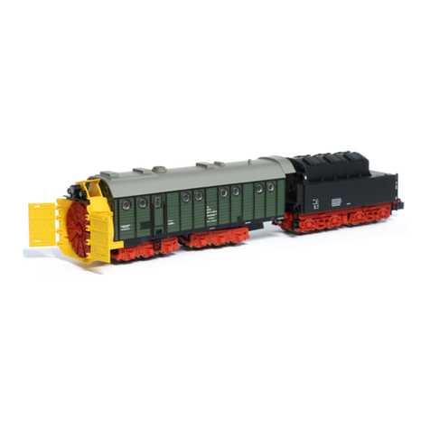
Modell der Dampfschneeschleuder Henschel
24966
F
D GB USA NL

2

3
Inhaltsverzeichnis Seite
Informationen zum Vorbild 4
Sicherheitshinweise 6
Wichtige Hinweise 6
Multiprotokollbetrieb 6
Schaltbare Funktionen 9
Parameter/Register 10
Betriebshinweise 26
Wartung und Instandhaltung 29
Ersatzteile 33
Table of Contents Page
Information about the prototype 4
Safety Notes 11
Important Notes 11
Multi-Protocol Operation 11
Controllable Functions 14
Parameter/Register 15
Information about operation 26
Service and maintenance 29
Spare Parts 33
Sommaire Page
Informations concernant le modèle réel 5
Remarques importantes sur la sécurité 16
Information importante 16
Mode multiprotocole 16
Fonctions commutables 19
Paramètre/Registre 20
Remarques sur l’exploitation 26
Entretien et maintien 29
Pièces de rechange 33
Inhoudsopgave Pagina
Informatie van het voorbeeld 5
Veiligheidsvoorschriften 21
Belangrijke aanwijzing 21
Multiprotocolbedrijf 21
Schakelbare functies 24
Parameter/Register 25
Opmerkingen over de werking 26
Onderhoud en handhaving 29
Onderdelen 33

4
Informationen zum Vorbild
Bei Schneelagen von über 1,5 Meter können Schneepflüge
die Bahnstrecken nicht mehr freiräumen. In diesen Fällen
kommen Schneeschleudern zum Einsatz. Das Vorbild des
Märklin-Modells, die Dampfschneeschleuder Bauart Hen-
schel, kann Schneeverwehungen bis zu einer Höhe von
6 Meter beseitigen. Um diese gewaltige Leistung zu ermög-
lichen, wird der auf der Schneeschleuder im Dampfkessel
erzeugte Dampf ausschließlich zum Antrieb des Schleuder-
rades verwendet. Da die Schneeschleuder keinen eigenen
Fortbewegungsantrieb besitzt, muss sie zusammen mit dem
zu ihr gehörenden Tender durch eine oder mehrere Schub-
lokomotiven gegen den Schnee gedrückt werden. Die Aus-
wurfrichtung wird durch die Drehrichtung des Schleuder-
rades und durch eine bewegliche Leitschaufel bestimmt.
Durch bewegliche Seitenflügel stellt sich die Dampfschnee-
schleuder auf das jeweilige Lichtraumprofil ein. Die Kohle im
Tender wird dabei durch Abdeckklappen gegen die Nässe
des weggeschleuderten Schnees geschützt.
Der nächste Winter kommt bestimmt! Auch auf Ihrer Modell-
bahn-Anlage.
Information about the Prototype
When snow depths exceed 1.5 meters (5 feet), snow plows
cannot clear railroad track right of way. Rotary snow plows
are used in these situations. The prototype of the Märklin
model, the Henschel design steam powered rotary snow
plow, can clear snowdrifts up to a depth of 6 meters (approx.
20 feet). The steam produced in the snow plow’s steam boiler
is used exclusively to power the rotary snow plow wheel to
enable this enormous output. Since the rotary snow plow has
no locomotion system of its own, it must be pushed along with
its tender against the snow by one or several locomotives.
The direction of throw is determined by the rotation of the
plow wheel and by a movable guide blade. The rotary snow
plow maintains the appropriate loading gauge by means of
movable side wings. The coal in the tender is protected by
hatches against the moisture of the flying snow.
Winter is on its way! Especially on your layout.
5
Informations concernant la locomotive réelle
Face à des chutes de neige dépassant 1,5 m, les chasse-
neige ne parviennent plus à dégager les voies ferrées. Dans
ce cas on utilise une fraise à neige à vapeur. Le modèle
Märklin reproduit cette fraise à neige construite par Hens-
chel, capable d’éliminer des congères atteignant 6 mètres.
Pour réaliser cette performance, la vapeur produite dans la
chaudière est exclusivement réservée à l’entraînement de la
fraise. Comme cet engin ainsi que son tender ne possède pas
de propulsion propre, une ou plusieurs locomotives doivent
le pousser contre la neige. Le sens d’évacuation est détermi-
né par l’orientation de panneaux déflecteurs réglables. Des
ailettes latérales mobiles permettent à la machine de s’adap-
ter au volume de neige à déplacer. Au cours de l’opération,
le charbon du tender est protégé par des couvercles l’isolant
de la neige projetée.
L’hiver prochain et son blanc cortège viendra sûrement!
Ainsi que ... sur votre réseau de modélisme
ferroviaire.
Informatie van het voorbeeld
Bij sneeuwlagen van meer dan 1,5 meter kunnen gewone
sneeuwploegen de lijnen niet meer ruimen. In die geval-
len komen sneeuwruimers in actie. Het voorbeeld van het
Märklin-model, de stoomsneeuwruimer type Henschel, kan
sneeuwophopingen tot een hoogte van 6 meter verwijde-
ren. Om deze geweldige prestatie te kunnen leveren, wordt
de stoom uit de stoomketel op de sneeuwruimer uitsluitend
voor de aandrijving van de rotor gebruikt. Omdat de sneeuw-
ruimer geen eigen aandrijving voor de voortbeweging heeft,
moet hij samen met zijn tender door een of meer duwende
locomotieven tegen de sneeuw aangedrukt worden. De uit-
werprichting wordt door de draairichting van de rotor en
door een beweegbare geleiding bepaald. Door beweegbare
zijvleugels wordt de stoomsneeuwruimer op het juiste profiel
van vrije ruimte ingesteld. De kolen in de tender worden door
afdekkleppen tegen het vocht van de weggeworpen sneeuw
beschermd.
De volgende winter komt er al aan! Ook op uw modelbaan.

6
Sicherheitshinweise
• DasModelldarfnurmiteinemdafürbestimmtenBe-
triebssystem eingesetzt werden.
• Analogmax.15Volt=,digitalmax.22Volt~.
•
Das Modell darf nur aus einer Leistungsquelle versorgt
werden.
• BeachtenSieunbedingtdieSicherheitshinweiseinder
Bedienungsanleitung zu Ihrem Betriebssystem.
• FürdenkonventionellenBetriebdesModellsmussdas
Anschlussgleis entstört werden. Dazu ist das Entstörset
611 655 zu verwenden. Für Digitalbetrieb ist das Entstör-
set nicht geeignet.
• ACHTUNG! Funktionsbedingte scharfe Kanten und Spitzen.
• SetzenSiedasModellkeinerdirektenSonneneinstrah-
lung, starken Temperaturschwankungen oder hoher
Luftfeuchtigkeit aus.
• VerbauteLED`sentsprechenderLaserklasse1nach
Norm EN 60825-1.
Wichtige Hinweise
• DieBedienungsanleitungunddieVerpackungsind
Bestandteile des Produktes und müssen deshalb aufbe-
wahrt sowie bei Weitergabe des Produktes mitgegeben
werden.
• FürReparaturenoderErsatzteilewendenSiesichbittean
Ihren Trix-Fachhändler.
• GewährleistungundGarantiegemäßderbeiliegenden
Garantieurkunde.
• Entsorgung:www.maerklin.com/en/imprint.html
• DiverseschaltbareFunktionen.
• ImAnalogbetriebstehennurderArbeitsscheinwerfer,
das Schleuderrad und der Rauchsatz zur Verfügung.
• DervolleFunktionsumfangistnurunterDCCundunter
mfx verfügbar.
• BefahrbarerMindestradius360mm.
Multiprotokollbetrieb
Analogbetrieb
DerDecoderkannauchaufanalogenAnlagenoderGleis-
abschnitten betrieben werden. Der Decoder erkennt die
analogeGleichspannung(DC)automatischundpasstsich
deranalogenGleisspannungan.EssindalleFunktionen,
die unter mfx oder DCC für den Analogbetrieb eingestellt
wurden aktiv (siehe Digitalbetrieb).
Digitalbetrieb
Der Decoder ist ein Multiprotokolldecoder. Der Decoder
kannunterfolgendenDigital-Protokolleneingesetztwerden:
mfx, DCC oder MM.
AdresseabWerk:DCC 03 / MM 64
Das Digital-Protokoll mit den meisten Möglichkeiten ist das
höchstwertige Digital-Protokoll. Die Reihenfolge der Digital-
ProtokolleistinderWertungfallend:
Priorität1:mfx
Priorität2:DCC
Priorität3:MM

7
Hinweis: Werden zwei oder mehrere Digital-Protokolle am
Gleiserkannt,übernimmtderDecoderautomatischdas
höchstwertige Digital-Protokoll; z.B. wird mfx & DCC erkannt
wird das mfx-Digital-Protokoll vom Decoder übernommen.
Einzelne Protokolle können über den Parameter CV 50
deaktiviert werden.
Hinweis: Beachten Sie, dass nicht alle Funktionen in allen
Digital-Protokollen möglich sind. Unter mfx und DCC können
einige Einstellungen von Funktionen, welche im Analog-
Betrieb wirksam sein sollen, vorgenommen werden.
Hinweise zum Digitalbetrieb
• DiegenaueVorgehensweisezumEinstellenderdiversen
Parameter entnehmen Sie bitte der Bedienungsanleitung
Ihrer Mehrzug-Zentrale.
mfx-Protokoll
Adressierung
• KeineAdresseerforderlich,jederDecodererhälteine
einmalige und eindeutige Kennung (UID).
• DerDecodermeldetsichaneinerCentralStationoder
Mobile Station mit seiner UID automatisch an.
• NameabWerk:Kassel 6481
Programmierung
• DieEigenschaftenkönnenüberdiegrascheOberäche
der Central Station bzw. teilweise auch mit der Mobile
Station programmiert werden.
• EskönnenalleCongurationVariablen(CV)mehrfach
gelesen und programmiert werden.
• DieProgrammierungkannentwederaufdemHaupt-oder
dem Programmiergleis erfolgen.
• DieDefaulteinstellungen(Werkseinstellungen)können
wieder hergestellt werden.
• Funktionsmapping:FunktionenkönnenmitHilfeder
Central Station 60212 (eingeschränkt) und mit der Central
Station 60213/60214/60215/60216/60226 beliebigen Funkti-
onstasten zugeordnet werden (siehe Hilfe in der Central
Station).

8
DCC-Protokoll
Adressierung
• MöglicheAdressen:Kurze,langeundTraktionsadresse
• Adressbereich:
1 – 127 (kurze Adresse, Traktionsadresse)
1 – 10239 (lange Adresse)
• JedeAdresseistmanuellprogrammierbar.
• KurzeoderlangeAdressewirdüberdieCVsausgewählt.
• EineangewandteTraktionsadressedeaktiviertdie
Standard-Adresse.
Programmierung
• DieEigenschaftenkönnenüberdieCongurationsVari-
ablen (CV) mehrfach geändert werden.
• DieCV-NummerunddieCV-Wertewerdendirekteinge-
geben.
• DieCVskönnenmehrfachgelesenundprogrammiert
werden (Programmierung auf dem Programmiergleis).
• DieCVskönnenbeliebigprogrammiertwerden.PoM
(Programmierung auf dem Hauptgleis PoM) ist nur bei
den in der CV-Tabelle gekennzeichneten CV möglich.
PoM muss von Ihrer Zentrale unterstützt werden (siehe
BedienungsanleitungihresGerätes).
• DieDefaulteinstellungen(Werkseinstellungen)können
wieder hergestellt werden.
• 14bzw.28/126Fahrstufeneinstellbar.
• AlleFunktionenkönnenentsprechenddemFunktions-
mapping geschaltet werden.
• WeitereInformation,sieheCV-TabelleDCC-Protokoll.
Es wird empfohlen, die Programmierungen grundsätzlich auf
dem Programmiergleis vorzunehmen.

9
1Trix Systems
Schaltbare Funktionen
DC
MS I 1
MS II
CS I/II
CS III
Arbeitsscheinwerfer / Streckensignallampen F0
Rauchgenerator F1
Geräusch:Schleuderrad F2
Geräusch:Dampfmaschine F3
Wechsel Arbeitsscheinwerfer / Streckensignallampen F4
Geräusch:Pfeifelang F5

10
CV Bedeutung Wert DCC ab Werk
1 Adresse 1 - 127 3
2 PoM Minimalgeschwindigkeit 0 - 255 50
3 PoM Anfahrverzögerung 0 - 255 35
4 PoM Bremsverzögerung 0 - 255 35
5 PoM Maximalgeschwindigkeit 0 - 255 100
8 Werkreset/Herstellerkennung 8 131
13 PoM Funktionen F1 - F8 im Analogbetrieb 0 - 255 0
14 PoM Funktionen F9 - F15 und Licht im Analogbetrieb 0 - 255 1
17 Erweiterte Adresse (oberer Teil) CV29,Bit5=1 192
18 Erweiterte Adresse (unterer Teil) CV29,Bit5=1 128
19 Traktionsadresse 0 - 255 0
21 PoM Funktionen F1 - F8 bei Traktion 0 - 255 0
22 PoM Funktionen F9 - F15 und Licht bei Traktion 0 - 255 0
29 PoM
Bit0:UmpolungFahrtrichtung
Bit1:AnzahlFahrstufen14oder28/128*
Bit2:DCCBetriebmitBremsstrecke(keinAnalogbetriebmöglich)
Bit5:kurze/langeAdresse
0 / 1
0 / 2
0 / 4
0 / 32
0, 1, 2, 3, 4, 5, 6, 7,
32, 34, 35, 36, 37,
38, 39 6
50 PoM
Alternative Protokolle (DCC kann sich selber nicht deaktivieren)
Bit0:AnalogACaus=0/AnalogACein=1
Bit1:AnalogDCaus=0/AnalogDCein=1
Bit2:fx(MM)aus=0/fx(MM)ein=1
Bit3:mfxaus=0/mfxein=1
0 / 1
0 / 2
0 / 4
0 / 8
0 - 15 15
63 PoM Lautstärke 0 - 255 255
* FahrstufenamLokdecoderundamSteuergerätmüssenübereinstimmen,essindsonstFehlfunktionenmöglich.

11
• Variouscontrollablefunctions.
• Onlytheworklights,therotarysnowplowblade,andthe
smoke unit are available in analog operation.
• ThefullrangeoffunctionsisonlyavailableunderDCC
and mfx.
• Minimumradiusforoperationis360mm/14-3/16“.
Multi-Protocol Operation
Analog Operation
This decoder can also be operated on analog layouts or ar-
eas of track that are analog. The decoder recognizes alter-
nating current (DC) and automatically adapts to the analog
track voltage. All functions that were set under mfx or DCC
for analog operation are active (see Digital Operation).
Digital Operation
The decoders are multi-protocol decoders. These decoders
canbeusedunderthefollowingdigitalprotocols:mfx,DCC
or MM.
Addresssetatthefactory:DCC 03 / MM 64
The digital protocol with the most possibilities is the highest
order digital protocol. The sequence of digital protocols in
descendingorderis:
Priority1:mfx
Priority2:DCC
Priority3:MM
Safety Notes
• Thismodelisonlytobeusedwiththeoperatingsystemit
is designed for.
• Analogmax.15voltsDC,digitalmax.22voltsAC.
• Thismodelmustneverbesuppliedwithpowerfrommore
than one power pack.
• Pleasemakenoteofthesafetynotesintheinstructions
for your operating system.
• Thefeedertrackmustbeequippedtopreventinterference
with radio and television reception, when the model is to
be run in conventional operation. The 611 655 interference
suppression set is to be used for this purpose.
• WARNING! Sharp edges and points required for operation.
• Donotexposethemodeltodirectsunlight,extreme
changes in temperature, or high humidity.
• TheLEDsinthisitemcorrespondtoLaserClass1accor-
ding to Standard EN 60825-1.
Important Notes
• Theoperatinginstructionsandthepackagingareacom-
ponent part of the product and must therefore be kept as
well as transferred along with the product to others.
• PleaseseeyourauthorizedTrixdealerforrepairsor
spare parts.
• Thewarrantycardincludedwiththisproductspecies
the warranty conditions.
• Disposing:www.maerklin.com/en/imprint.html

12
Note: If two or more digital protocols are recognized in the
track, the decoder automatically takes on the highest value
digital protocol.For example, if mfx & DCC are recognized,
the mfx digital protocol is taken on by the decoder. Individual
protocols can be deactivated with Parameter CV 50.
Note: Please note that not all functions are possible in all
digital protocols. Several settings for functions, which are
supposed to be active in analog operation, can be done
under mfx and DCC.
Notes on digital operation
• Theoperatinginstructionsforyourcentralunitwillgive
you exact procedures for setting the different parame-
ters.
mfx Protocol
Addresses
• Noaddressisrequired;eachdecoderisgivenaone-
time, unique identifier (UID).
• ThedecoderautomaticallyregistersitselfonaCentral
Station or a Mobile Station with its UID.
• Namesetatthefactory:Kassel 6481
Programming
• Thecharacteristicscanbeprogrammedusingthe
graphic screen on the Central Station or also partially
with the Mobile Station.
• AlloftheCongurationVariables(CV)canbereadand
programmed repeatedly.
• Theprogrammingcanbedoneeitheronthemaintrackor
the programming track.
• Thedefaultsettings(factorysettings)canbeproduced
repeatedly.
• Functionmapping:Functionscanbeassignedto
any of the function buttons with the help of the
60212 Central Station (with limitations) and with the
60213/60214/60215/60216/60226 Central Station (See help
section in the Central Station).

13
DCC Protocol
Addresses
• Possibleaddresses:short,long,andm.u.address
• Addressrange:
1 – 127 (short address, m.u. address)
1 – 10239 (long address)
• Everyaddresscanbeprogrammedmanually.
• AshortoralongaddressisselectedusingtheCVs.
• Amultipleunitaddressthatisbeinguseddeactivatesthe
standard address.
Programming
• Thecharacteristicscanbechangedrepeatedlyusingthe
Configuration Variables (CV).
• TheCVnumbersandtheCVvaluesareentereddirectly.
• TheCVscanbereadandprogrammedrepeatedly.(Pro-
gramming is done on the programming track.)
• TheCVscanbeprogrammed,asyoudesire.PoM(Pro-
gramming on the layout track) is only possible with those
CVs marked in the CV table. PoM must be supported
by your central controller (see the instructions for your
controller).
• Thedefaultsettings(factorysettings)canbeproduced
repeatedly.
• 14or28/126speedlevelscanbeset.
• Allofthefunctionscanbecontrolledaccordingtothe
function mapping (see CV description).
• SeetheCVdescriptionfortheDCCprotocolforadditional
information.
We recommend that in general programming should be
done on the programming track.

14
1Trix Systems
Controllable Functions
DC
MS I 1
MS II
CS I/II
CS III
Work lights / Headlights F0
Smoke generator F1
Soundeffect:Rotaryplowblades F2
Soundeffect:Streamengine F3
Choose between work lights and headlights F4
Soundeffect:Longwhistleblast F5

15
* Thespeedlevelsonthelocomotivedecoderandonthecontrollermustagreewitheachother;otherwise,
you may have malfunctions.
CV Discription DCC Value Factory-Set
1 Address 1 - 127 3
2 PoM Minimum Speed 0 - 255 50
3 PoM Acceleration delay 0 - 255 35
4 PoM Braking delay 0 - 255 35
5 PoM Maximum speed 0 - 255 100
8 Factory Reset / Manufacturer Recognition 8 131
13 PoM Functions F1 - F8 in analog operation 0 - 255 0
14 PoM Functions F9 - F15 and lights in analog operation 0 - 255 1
17 Extended address (upper part) CV29,Bit5=1 192
18 Extended address (lower part) CV29,Bit5=1 128
19 Multiple Unit Address 0 - 255 0
21 PoM Functions F1 - F8 on Multiple Unit 0 - 255 0
22 PoM Functions F9 - F15 and lights on Multiple Unit 0 - 255 0
29 PoM
Bit0:Reversingdirectionoftravel
Bit1:Numberofspeedlevels14or28/128*
Bit2:DCCoperationwithabrakingarea(noanalogoperation
possible)
Bit5:short/longaddress
0 / 1
0 / 2
0 / 4
0 / 32
0, 1, 2, 3, 4, 5, 6,
7, 32, 34, 35, 36,
37, 38, 39 6
50 PoM
Alternative Protocols (DCC cannot deactivate itself)
Bit0:AnalogACoff=0/AnalogACon=1
Bit1:AnalogDCoff=0/AnalogDCon=1
Bit2:fx(MM)off=0/fx(MM)on=1
Bit3:mfxoff=0/mfxon=1
0 / 1
0 / 2
0 / 4
0 / 8
0 - 15 15
63 PoM Volume 0 - 255 255

16
Remarques importantes sur la sécurité
• Lemodèlenepeutêtreutiliséequ‘aveclesystème
d‘exploitationindiqué.
• Analogiquemax.15Volt=,digitalmax.22Volt~.
• Lemodèlenepeutpasêtrealimentéeélectriquementpar
plusd‘unesourcedecourantàlafois.
• Ilestimpératifdetenircomptedesremarquessurla
sécuritédécritesdanslemoded‘emploidevotresystème
d‘exploitation.
• Pourl’exploitationdelemodèleenmodeconventionnel,
lavoiederaccordementdoitêtredéparasitée.Acet
effet, utiliser le set de déparasitage réf. 611 655. Le set de
déparasitage ne convient pas pour l’exploitation en mode
numérique.
•
ATTENTION! Pointes et bords coupants lors du fonctionne-
ment du produit.
• Nepasexposerlemodèleàunensoleillementdirect,
à de fortes variations de température ou à un taux
d‘humiditéimportant.
• LesDELinstalléescorrespondentàlaclasselaser1
selon la norme EN 60825-1.
Information importante
• Lanoticed‘utilisationetl’emballagefontpartieintégrante
duproduit;ilsdoiventdoncêtreconservéset,lecas
échéant, transmis avec le produit.
• Pourtouteréparationouremplacementdepièces,adres-
sez vous à votre détaillant-spécialiste Trix.
• Garantielégaleetgarantiecontractuelleconformément
au certificat de garantie ci-joint.
• Elimination:www.maerklin.com/en/imprint.html
• Diversesfonctionscommutables.
•
Seuls les feux de travail, le chasse-neige rotatif et le
générateur de fumée sont disponibles en mode exploitation
analogique.
• L’intégralitédesfonctionsestdisponibleuniquementen
exploitation DCC et mfx.
• Rayonminimald’inscriptionencourbe360mm.
Mode multiprotocole
Mode analogique
On peut aussi faire fonctionner le décodeur sur des instal-
lations ou des sections de voie analogiques. Le décodeur
identifie automatiquement la tension de voie analogique
(DC). Toutes les fonctions qui ont été paramétrée pour le
mode analogique sous mfx ou sous DCC sont actives (voir
mode numérique).
Mode numérique
Les décodeur sont des décodeur multiprotocole. Le
décodeurpeutêtreutiliséaveclesprotocolesnumériques
suivants:mfx,DCC,MM.
Adresseencodéeenusine:DCC 03 / MM 64
Le protocole numérique offrant les possibilités les plus
nombreuses est le protocole numérique à bit de poids
fort. La hiérarchisation des protocoles numériques est
descendante:
Priorité1:mfx
Priorité2:DCC
Priorité3:MM

17
Indication : Si deux ou plus de deux protocoles numériques
sont reconnus sur la voie, le décodeur choisit automatique-
ment le protocole numérique le plus significatif. Entre les
protocoles mfx & DCC par exemple, le décodeur choisira
le protocole numérique mfx. Vous pouvez désactiver les
différents protocoles via le paramètre CV 50.
Indication : remarquez que toutes les fonctions ne peuvent
pasêtreactionnéesdanstouslesprotocolesnumériques.
Sous mfx et sous DCC, il est possible de procéder à
quelquesparamétragesdefonctionsdevantêtreactives
dans le cadre de l’exploitation analogique.
Remarques relatives au fonctionnement en mode digital
• Encequiconcernelaprocédurederéglagedesdivers
paramètres,veuillezvousréféreraumoded‘emploide
votre centrale de commande multitrain.
Protocole mfx
Adressage
• Aucuneadressen’estnécessaire,ledécodeurreçoittou-
tefois une identification unique et non équivoque (UID).
• AvecsonUID,ledécodeurindiqueautomatiquement
à une station centrale ou à une station mobile qu’il est
connecté.
• Nomencodeeenusine:Kassel 6481
Programmation
• Lescaractéristiquespeuventêtreprogramméespar
l’intermédiaire de la couche graphique de la station cen-
trale, voire en partie aussi au moyen de la station mobile.
• Touteslescongurationsvariables(CV)peuventêtrelues
etprogramméesdefaçonréitérée.
• Laprogrammationpeutêtreréaliséesoitsurlavoie
principale, soit sur la voie de programmation.
• Lesparamétragespardéfaut(paramétragesusine)
peuventêtrerétablis.
• Mappagedesfonctions:lesfonctionspeuventêtre
affectées à de quelconques touches de fonction au
moyen de la station centrale (60212) (restreinte) et avec
la station centrale 60213/60214/60215/60216/60226 (voir
Aide au niveau de la station centrale).

18
Protocole DCC
Adressage
• Adressepossibles:Courtes,longuesetadressesdetraction
• Catégoried’adresse:
1 à 127 (adresses courtes, adresses de traction)
1 à 10239 (adresses longues)
• Chaqueadresseestprogrammablemanuellement.
• L’adressebrèveoulongueestchoisieparl’intermédiaire
des CVs.
• Uneadressedetractionutiliséedésactivel’adresse
standard.
Programmation
• Lescaractéristiquespeuventêtremodiéesdefaçon
réitérée par l’intermédiaire des variables de configuration
(CVs).
• Touteslescongurationsvariables(CV)peuventêtrelues
etprogramméesdefaçonréitérée.
• Laprogrammationpeutêtreréaliséesoitsurlavoie
principale, soit sur la voie de programmation.
• LesCVpeuventêtreprogramméeslibrement.LaPoM
(programmation sur la voie principale) est possible
uniquement pour les CV signalées dans le tableau des CV.
LaPoMdoitêtrepriseenchargeparvotrecentrale(voir
la notice d’utilisation de votre appareil).
• Lesparamétragespardéfaut(paramétragesusine)
peuventêtrerétablis.
• 14voire28/126cransdemarchesontparamétrables.
• Touteslesfonctionspeuventêtrecommutéesenfonction
du mappage des fonctions (voir le descriptif des CVs).
• Pourtouteinformationcomplémentaire,voirletableau
des CVs, protocole DCC.
Il est recommandé, de réaliser la programmation, fonda-
mentalement, sur la voie de programmation.

19
1Trix Systems
Fonctions commutables
DC
MS I 1
MS II
CS I/II
CS III
Projecteur / feux de signalisation F0
Générateurdefumée F1
Bruitage:Rotationdelafraise F2
Bruitage:Machineàvapeur F3
Alternance entre le projecteur et les feux de signalisation F4
Bruitage:Sifetlongueur F5

20
CV Affectation DCC Valeur Parm. Usine
1 Adresse 1 - 127 3
2 PoM Vitesse minimale 0 - 255 50
3 PoM Temporisationd‘accélération 0 - 255 35
4 PoM Temporisation de freinage 0 - 255 35
5 PoM Vitesse maximale 0 - 255 100
8 Réinitialisation d’usine/identification du fabricant 8 131
13 PoM Fonctions F1 - F8 en mode analogique 0 - 255 0
14 PoM Fonctions F9 - F15 et éclairage en mode analogique 0 - 255 1
17 Adresse étendue (partie supérieure) CV29,Bit5=1 192
18 Adresse étendue (partie inférieure) CV29,Bit5=1 128
19 Adresse traction 0 - 255 0
21 PoM Fonctions F1 - F8 pour traction 0 - 255 0
22 PoM Fonctions F9 - F15 et éclairage traction 0 - 255 0
29 PoM
Bit0:Inversiondusensdemarche
Bit1:Nombredecransdemarche14ou28/128*
Bit2:ExploitationDCCavecsectiondefreinage(exploitation
analogique impossible)
Bit5:Adressecourte/longue
0 / 1
0 / 2
0 / 4
0 / 32
0, 1, 2, 3, 4, 5, 6,
7, 32, 34, 35, 36,
37, 38, 39 6
50 PoM
Autresprotocoles(DCCnepeutpassedésactiverlui-même)
Bit0:AnalogiqueCAhorsfonction=0/analogiqueCAenfonction=1
Bit1:AnalogiqueCChorsfonction=0/analogiqueCCenfonction=1
Bit2:fx(MM)horsfonction=0/fx(MM)enfonction=1
Bit3:mfxhorsfonction=0/mfxenfonction=1
0 / 1
0 / 2
0 / 4
0 / 8
0 - 15 15
63 PoM Volume 0 - 255 255
* Pourévitertoutdysfonctionnement,lescransdemarchesurledécodeurdelocodoiventimpérativement
coïncider avec ceux de l’appareil de commande.
Other manuals for Henschel
1
This manual suits for next models
1
Table of contents
Languages:
Other Trix Toy manuals

Trix
Trix BR 798/998 User manual

Trix
Trix Minitrix Kof II User manual

Trix
Trix BR 150 22151 User manual

Trix
Trix Minitrix ICE User manual

Trix
Trix minitrix BR 212 User manual

Trix
Trix 701 Series User manual

Trix
Trix 11304 User manual

Trix
Trix H0 Baureihe 44 User manual

Trix
Trix BB 22200 Series User manual

Trix
Trix 21520 User manual