Trix 22290 User manual

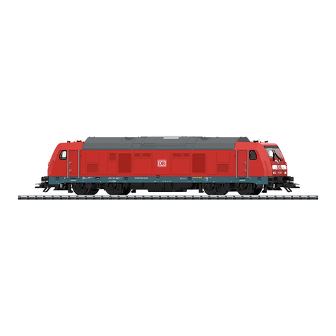
Modell der Baureihe V 90
22290

2
Inhaltsverzeichnis:
Seite
Informationen zum Vorbild 4
Sicherheitshinweise 5
Wichtige Hinweise 5
Funktionen 5
Hinweise zum Digitalbetrieb 5
Schaltbare Funktionen 6
Parameter / Register 7
Wartung und Instandhaltung 29
Ersatzteile 34
Table of Contents:
Page
Information about the prototype 4
Safety Notes 8
Important Notes 8
Function 8
Notes on digital operation 8
Controllable Functions 9
Parameter / Register 10
Service and maintenance 29
Spare Parts 34
Sommaire :
Page
Informations concernant la locomotive réelle 4
Remarques importantes sur la sécurité 11
Informations importante 11
Fonctionnement 11
Remarques relatives au fonctionnement
en mode digital 11
Fonctions commutables 12
Paramètre / Registre 13
Entretien et maintien 29
Pièces de rechange 34
Inhoudsopgave:
Pagina
Informatie van het voorbeeld 4
Veiligheidsvoorschriften 14
Belangrijke informatie 14
Functies 14
Aanwijzingen voor digitale besturing 14
Schakelbare functies 15
Parameter / Register 16
Onderhoud en handhaving 29
Onderdelen 34

3
Indice de contenido:
Página
Aviso de seguridad 17
Informaciones importantes 17
Funciones 17
Informaciones para el funcionamiento digital 17
Funciones posibles 18
Parámetro / Registro 19
El mantenimiento 29
Recambios 34
Indice del contenuto:
Pagina
Avvertenze per la sicurezza 20
Avvertenze importanti 20
Funzioni 20
Avvertenze per la funzione digitale 20
Funzioni commutabili 21
Parametro / Registro 22
Manutenzione ed assistere 29
Pezzi di ricambio 34
Innehållsförteckning:
Sida
Säkerhetsanvisningar 23
Viktiga informationer 23
Funktioner 23
Anvisningar för digital drift 23
Kopplingsbara funktioner 24
Parameter / Register 25
Underhåll och reparation 29
Reservdelar 34
Indholdsfortegnelse:
Side
Vink om sikkerhed 26
Vigtige oplysninger 26
Funktioner 26
Henvisninger til digitaldrift 26
Styrbare funktioner 27
Parameter / Register 28
Service og reparation 29
Reservedele 34

4
Informationen zum Vorbild:
Neben der Einführung von neuen Diesellokomotiven für den
Streckendienst musste die Deutsche Bundesbahn als Ersatz
für die Dampflokomotiven auch neue Lokomotiven für den
Rangierdienst beschaffen. Neben der Baureihe V 60, die in
den 1950er-Jahren in Dienst gestellt wurde, zeichnete sich
der Bedarf nach einem leistungsfähigeren Loktyp ab. Diese
Lücke wurde ab 1964 mit der von der Firma MaK entwickelten
Baureihe V 90 geschlossen. Der eingebaute 12-Zylinder-
Dieselmotor, der von dem Motor aus der V 100 abgeleitet ist,
stellte mit einer Leistung von knapp 810 kW (1.100 PS) genü-
gend Potenzial zur Erfüllung dieser Aufgabe zur Verfügung.
Als reine Rangierlok wurde bei der V 90 auf den Einbau einer
Zugheizung verzichtet. Ab 1968 wurde die Lok bei der DB als
Baureihe 290 eingereiht.
Informations concernant la locomotive réelle:
A la fin de la traction vapeur, la Deutsche Bundesbahn se vit
obligée non seulement d’introduire de nouvelles locomotives
diesel pour le service de ligne, mais également d’acquérir de
nouvelles machines de manœuvre. Outre la série V 60 mise
en service dans les années 1950, se fit sentir le besoin d’un
type de locomotive plus puissant. La série V 90, conçue par la
firme MaK, vint combler cette lacune à partir de 1964. Avec
une puissance de tout juste 810 kW (1100 ch), son moteur
diesel à 12 cylindres - dérivé de celui de la V 100 - offrait un
potentiel suffisant pour satisfaire à cette exigence. La V 90
étant destinée exclusivement aux manœuvres, on se dispensa
de l’installation d’un dispositif de chauffage pour le train. A
partir de 1968, la locomotive fut immatriculée dans la série
290 de la DB.
Informatie van het voorbeeld:
Naast de invoering van nieuwe diesellocomotieven voor de
lijndienst moest de Deutsche Bundesbahn als vervanging
voor de stoomlocomotieven ook nieuwe locomotieven voor
de rangeerdienst aanschaffen. Naast de serie V 60, die in de
jaren ’50 in dienst gesteld werd, tekende de behoefte aan een
sterke loctype zich af. Dit gat werd vanaf 1964 met de door de
firma MaK ontwikkelde serie V 90 gesloten. De ingebouwde
12 cilinder-dieselmotor, die van de motor uit de V 100 afgeleid
is, stelde met een vermogen van bijna 810 kW (1100 pk)
voldoende potentiaal voor de verwezenlijking van deze taak
ter beschikking. Als zuivere rangeerloc werd bij de V 90 op de
inbouw van treinverwarming afgezien. Vanaf 1968 werd de loc
bij de DB als serie 290 opgenomen.
Information about the Prototype:
In addition to introducing new diesel locomotives for road
service, the German Federal Railroad had to procure new loco-
motives for switching work as replacements for steam locomo-
tives. After the class V 60, which was placed into service in the
1950’s, the need became acute for a more powerful locomotive
type. This gap was closed starting in 1964 with the class V 90
developed by the firm MaK. The 12 cylinder diesel motor built
into the locomotive was derived from the motor for the class
V 100 and provided enough power at just 810 kilowatts / 1,100
horsepower to fulfill this task. The V 90 was switch engine pure
and simple and thus dispensed with having a train heating
system. From 1968 on this locomotive was designated by the
DB as the class 290.
5
Sicherheitshinweise
• DieLokdarfnurmiteinemdafürbestimmtenBetriebs-
system eingesetzt werden.
• Analogmax.15Volt=,digitalmax.22Volt~.
• DieLokdarfnichtmitmehralseinerLeistungsquelle
versorgt werden.
• BeachtenSieunbedingtdieSicherheitshinweiseinder
Bedienungsanleitung zu Ihrem Betriebssystem.
•FürdenkonventionellenBetriebderLokmussdas
Anschlussgleis entstört werden. Dazu ist das Entstörset
611 655 zu verwenden. Für Digitalbetrieb ist das Entstörset
nicht geeignet.
•SetzenSiedasModellkeinerdirektenSonneneinstrah-
lung, starken Temperaturschwankungen oder hoher
Luftfeuchtigkeit aus.
•ACHTUNG! Funktionsbedingte scharfe Kanten und Spitzen.
Wichtige Hinweise
•DerbefahrbareMindestradiusist356mm.
•DieBedienungsanleitungunddieVerpackungsindBe-
standteil des Produktes und müssen deshalb aufbewahrt
sowie bei Weitergabe des Produktes mitgegeben werden.
•FürReparaturenoderErsatzteilewendenSiesichbittean
Ihren Trix-Fachhändler.
•http://www.maerklin.com/en/imprint.html
Funktionen
• EingebauteElektronikzumwahlweisenBetriebmit
konventionellem Gleichstrom-Fahrgerät, Trix Systems oder
Digitalsystemen nach NMRA-Norm.
• AutomatischeSystemerkennungzwischenDigital-und
Analog-Betrieb.
•DervolleFunktionsumfangistnurunterTrixSystemsund
unter DCC verfügbar.
• Eingebaute,fahrtrichtungsabhängigeStirnbeleuchtung.
Im Digitalbetrieb schaltbar.
Hinweise zum Digitalbetrieb
•BeimerstenBetriebineinemDigital-System(Selectrix
oder DCC) muss der Decoder auf dieses Digital-System
eingestellt werden. Dazu ist der Decoder einmal in diesem
Digitalsystem zu programmieren.
• DiegenaueVorgehensweisezumEinstellenderdiversen
Parameter entnehmen Sie bitte der Bedienungsanleitung
Ihrer Mehrzug-Zentrale.
•DieabWerkeingestelltenWertesindsogewählt,dass
bestmöglichstes Fahrverhalten gewährleistet ist.
• DerBetriebmitgegenpoligerGleichspannungimBremsab-
schnitt ist mit der werkseitigen Einstellung nicht möglich. Ist
diese Eigenschaft gewünscht, so muss auf den konventio-
nellenGleichstrombetriebverzichtetwerden(CV29/Bit2=0).
Garantie
•GewährleistungundGarantiegemäßderbeiliegenden
Garantieurkunde.

6
Schaltbare Funktionen
Stirnbeleuchtung an Licht-Taste Funktion f0
Telex Kupplung vorne ein/aus — — Funktion 1 Funktion f1
Telex Kupplung hinten ein/aus — — Funktion 2 Funktion f2
ABV, aus — — Funktion 4 Funktion f4
STOP mobile station
15
2
7
1
6
STOP
PR
3
8
Sx
5
ON
Lz
4
9
1/2
Central-Control
66800 f0 f8 f0f8
• Nachabgeschlossenem Entkupplungsvorgang muss
die Funktion durch die Taste am Steuergerät deaktiviert
werden.
• Fehlfunktionen,diedurchÄnderungderwerkseitigen
Einstellungen der Lokelektronik verursacht werden, sind
vom Bediener selbst verursacht und damit kein Reklamati-
onsgrund bezüglich der Garantie- oder Gewährleistungsan-
sprüche.

7
CV Bedeutung Werte DCC Wert DCC Wert Sx
1 Adresse 1 – 127 3 1
2Minimalgeschwindigkeit 0 – 15 0 —
3 Anfahrverzögerung 0 – 127 5 3
4 Bremsverzögerung 0 – 127 4 —
5 Maximalgeschwindigkeit 1 – 7 6 6
8 Werksreset 8 0 —
17 Erweiterte Adresse (oberer Teil) CV29,Bit5=1 192 —
18 Erweiterte Adresse (unterer Teil) CV29,Bit5=1 128 —
29
Bit 0: Umpolung Fahrtrichtung
Bit 1: Anzahl Fahrstufen 14 oder 28/128
Bit 2: DCC Betrieb mit Bremsstrecke oder Gleichstrombetrieb
Bit 5: Adressumfang 7 Bit / 14 Bit
Wert
0 / 1
0 / 2
0 / 4
0 / 32
***
0, 1, 2, 3, 4, 5, 6,
7, 32, 34, 35, 36,
37, 38, 39
6 —
*** Die Werte der gewünschten Einstellungen sind zu addieren!

8
Functions
• Built-inelectroniccircuitforoperationwithaconventi-
onal DC power pack, Trix Systems or NMRA DCC digital
systems.
• Automaticsystemrecognitionbetweendigitalandanalog
operation.
•ThefullrangeoffunctionsisonlyavailableunderTrix
Systems and under DCC.
• Built-inheadlightsthatchangeoverwiththedirectionof
travel. They can be turned on and off in digital operation.
Notes on digital operation
•Thersttimethelocomotiveisusedinadigitalsystem
(Selectrix or DCC), the decoder must be set for this digital
system. To do this, the decoder must be programmed once
in this digital system.
•Theoperatinginstructionsforyourcentralunitwillgive
you exact procedures for setting the different parameters.
• Thevaluessetatthefactorywereselectedtoguarantee
the best possible running characteristics.
• Thesettingdoneatthefactorydoesnotpermitoperation
with opposite polarity DC power in the braking block. If
you want this characteristic, you must do without conven-
tionalDCpoweroperation(CV29/Bit2=0).
Warrenty
•Thewarrantycardincludedwiththisproductspeciesthe
warranty conditions.
Safety Notes
• Thislocomotiveisonlytobeusedwiththeoperating
system it is designed for.
• Analogmax.15voltsDC,digitalmax.22voltsAC.
• Thislocomotivemustnotbesuppliedwithpowersimulta-
neously by more than one power pack.
• Pleasemakenoteofthesafetynotesintheinstructions
for your operating system.
•Thefeedertrackmustbeequippedtopreventinterference
with radio and television reception, when the locomotive
is to be run in conventional operation. The 611 655 inter-
ference suppression set is to be used for this purpose.
The interference suppression set is not suitable for digital
operation.
•Donotexposethemodeltodirectsunlight,extreme
changes in temperature, or high humidity.
•WARNING! Sharp edges and points required for operation.
Important Notes
•Theminimumradiusthislocomotivecannegotiateis356
mm / 14”.
•Theoperatinginstructionsandthepackagingareacom-
ponent part of the product and must therefore be kept as
well as transferred along with the product to others.
•PleaseseeyourauthorizedTrixdealerforrepairsorspare
parts.
•http://www.maerklin.com/en/imprint.html

9
Controllable Functions
Headlights on Headlight button Function f0
Front Telex coupler on/off — — Function 1 Function f1
Rear Telex coupler on/off — — Function 2 Function f2
ABV, off — — Function 4 Function f4
STOP mobile station
15
2
7
1
6
STOP
PR
3
8
Sx
5
ON
Lz
4
9
1/2
Central- Control
66800 f0 f8 f0f8
• Aftertheuncoupling procedure is completed, this
function must also be deactivated with the button on the
locomotive controller.
• Malfunctionsresultingfromchangestothefactory
settings of the locomotive electronics are caused by the
operator and do not give grounds for complaint under our
guarantee or warranty obligations.

10
CV Discription DCC Value DCC Sx
1 Adress 1 – 127 3 1
2 Minimum speed 0 – 15 0 —
3 Acceleration delay 0 – 127 5 3
4 Braking delay 0 – 127 4 —
5 Maximum speed 1 – 7 6 6
8 Factory Reset 8 0 —
17 Extended address (upper part) CV29,Bit5=1 192 —
18 Extended address (lower part) CV29,Bit5=1 128 —
29
Bit 0: Travel direction polarity reversal
Bit 1: number of speed levels 14 or 28/128
Bit 2: DCC Operation with braking Block. DC power Operation
Bit 5: Adress size 7 Bit / 14 Bit
Value
0 / 1
0 / 2
0 / 4
0 / 32
***
0, 1, 2, 3, 4, 5, 6,
7, 32, 34, 35, 36,
37, 38, 39
6 —
*** The values for the desired settings must be added.

11
Remarques importantes sur la sécurité
• Lalocomotivenepeutêtreutiliséequ‘aveclesystème
d‘exploitationindiqué.
• Analogiquemax.15Volt=,numériquemax.22Volt~.
• Lalocomotivenepeutpasêtrealimentéeélectriquement
parplusd‘unesourcedecourantàlafois.
• Ilestimpératifdetenircomptedesremarquessurla
sécuritédécritesdanslemoded‘emploidevotresystème
d‘exploitation.
•Pourl’exploitationdelalocomotiveenmodeconventi-
onnel,lavoiederaccordementdoitêtredéparasitée.A
cet effet, utiliser le set de déparasitage réf. 611 655. Le set
de déparasitage ne convient pas pour l’exploitation en
mode numérique.
•Nepasexposerlemodèleàunensoleillementdirect,àde
fortesvariationsdetempératureouàuntauxd‘humidité
important.
•ATTENTION! Pointes et bords coupants lors du fonction-
nement du produit.
Informations importante
•Lerayonminimald‘inscriptionencourbeestde356mm.
•Lanoticed‘utilisationetl’emballagefontpartieintégrante
duproduit;ilsdoiventdoncêtreconservéset,lecas
échéant, transmis avec le produit.
•Pourtouteréparationouremplacementdepièces,
adressez vous à votre détaillant-spécialiste Trix.
•http://www.maerklin.com/en/imprint.html
Fonctionnement
• Electroniqueintégréepourexploitationauchoixavec
transformateur-régulateur conventionnel délivrant du
courant continu, avec Trix Systems ou avec des systèmes
de conduite digitale conformes aux normes NMRA.
• Reconnaissanceautomatiquedusystèmeentreexploita-
tions numérique et analogique.
•L’intégralitédesfonctionsestdisponibleuniquementen
exploitation Trix Systems et DCC.
• Feuxdesignalisations‘inversantselonlesensdemarche;
feux commutables en exploitation digital.
Remarques relatives au fonctionnement en mode digital
•Unepremièreexploitationensystèmenumérique(Selec-
trix ou DCC) exige le réglage correspondant du décodeur.
Aceteffet,ledécodeurdoitêtreprogramméunefoisdans
ce système numérique.
•Encequiconcernelaprocédurederéglagedesdivers
paramètres,veuillezvousréféreraumoded‘emploide
votre centrale de commande multitrain.
•Lesvaleursparamétréesd’usinesontchoisiesdemanièreà
garantir le meilleur comportement de roulement possible.
• L’exploitationaveccourantcontinudepolaritéinversedansles
sections de freinage n’est pas possible avec le réglage d’usine. Si
cette propriété est désirée, il faut alors renoncer à l’exploitation
conventionnelleencourantcontinu(CV29/Bit2=0).
Garantie
• Garantielégaleetgarantiecontractuelleconformémentau
certificat de garantie ci-joint.

12
• Unefoisleprocessusde dételage terminé, la fonction doit
égalementêtredésactivéevialatouchedel’appareilde
commande.
•
Les défaillances au niveau du fonctionnement, découlant de
la modification des réglages faits en usine sur le système
électronique de la locomotive, sont déclenchées par
l‘opérateuretneconstituentparconséquentaucuneraison
de réclamation; elles ne donnent de ce fait aucun droit de
recours en garantie contractuelle ou commerciale.
Fonctions commutables
Fanal Activé Touche éclairage Fonction f0
Attelage Telex à l’avant allumées/éteintes — — Fonction 1 Fonction f1
Attelage Telex à l’arrière allumées/éteintes — — Fonction 2 Fonction f2
ABV, désactivé — — Fonction 4 Fonction f4
STOP mobile station
15
2
7
1
6
STOP
PR
3
8
Sx
5
ON
Lz
4
9
1/2
Central-Control
66800 f0 f8 f0f8

13
*** Les valeurs des réglages désirés sont à additioner.
CV Affectation DCC Valeur DCC Sx
1 Adresse 1 – 127 3 1
2Vitesse minimale 0 – 15 0 —
3Temporisationd‘accélération 0 – 127 5 3
4 Temporisation de freinage 0 – 127 4 —
5 Vitesse maximale 1 – 7 6 6
8 Réinitialisation d’usine 8 0 —
17 Adresse étendue (partie supérieure) CV29,Bit5=1 192 —
18 Adresse étendue (partie inférieure) CV29,Bit5=1 128 —
29
Bit 0: inversion de polarité, sens de marche
Bit 1: Nombre de crans de marche 14 ou 28/128
Bit 2: Exploitation DCC avec zone de freinage.
DCC et courant continu
Bit5:tailled‘adresse7Bit/14Bit
Valeur
0 / 1
0 / 2
0 / 4
0 / 32
***
0, 1, 2, 3, 4, 5, 6,
7, 32, 34, 35, 36,
37, 38, 39
6 —

14
Veiligheidsvoorschriften
• Delocmagalleenmeteendaarvoorbestemdbedrijfssy-
steem gebruikt worden.
• Analoogmax.15Volt=,digitaalmax.22Volt~.
• Delocmagnietvanuitmeerdanéénstroomvoorziening
gelijktijdig gevoed worden.
• Leesookaandachtigdeveiligheidsvoorschrifteninde
gebruiksaanwijzing van uw bedrijfssysteem.
•Voorhetconventionelebedrijfmetdelocdientde
aansluitrail te worden ontstoort. Hiervoor dient men de
ontstoor-set
611 655 te gebruiken. Voor het digitale bedrijf is deze
ontstoor-set niet geschikt.
•Stelhetmodelnietblootaanindirectezonnestraling,
sterke temperatuurwisselingen of hoge luchtvochtigheid.
•OPGEPAST! Functionele scherpe kanten en punten.
Belangrijke informatie
•Deberijdbareminimaleradiusis356mm.
•Degebruiksaanwijzingendeverpakkingzijneenbestand-
deel van het product en dienen derhalve bewaard en
meegeleverd te worden bij het doorgeven van het product.
•VoorreparatiesenonderdelenkuntzichtotUwTrixhan-
delaar wenden.
•http://www.maerklin.com/en/imprint.html
Functies
• Ingebouwdeelektronicadiehetmogelijkmaaktomnaar
keuze met, een conventionele gelijkstroomrijregelaar, Trix
Systems of digitaalsysteem volgens NMRA-norm te rijden.
• Automatischesysteemherkenningtussendigitaal-en
analoogbedrijf.
•Devolledigetoegangtotallefunctiesisalleenmogelijk
met Trix Systems of met DCC bedrijf.
• Ingebouwde,rijrichtingsafhankelijkefrontverlichting.
Aanwijzingen voor digitale besturing
•Voorheteerstebedrijfmeteendigitaal-systeem(Selectrix
of DCC) moet de decoder op dat digitale systeem worden
ingesteld. Daarvoor moet de decoder éénmaal met dat
digitale systeem geprogrammeerd worden.
•Hetopdejuistewijzeinstellenvandediverseparame-
ters staat beschreven in de handleiding van uw digitale
Centrale.
•Devanafdefabriekingesteldewaardenzijnzoingesteld
dat de rij-eigenschappen optimaal zijn.
• Hetbedrijfmettegengepooldegelijkspanningindeafrem-
sectie is met de fabrieksinstelling niet mogelijk. Indien deze
eigenschap wenselijk is, dan moet worden afgezien van het
conventioneelgelijkstroombedrijf(CV29/Bit2=0).
Garantie
•Vrijwaringengarantieovereenkomstighetbijgevoegde
garantiebewijs.

15
• Nahetafsluiten van de ontkoppelingsprocudure dient de
functie, door nogmaals op de toets van het besturingsap-
paraat te drukken, gedeactiveerd te worden.
• Functiestoringendiedoorwijzigingvandefabrieksmatige
instellingen van loc-elektronica veroorzaakt worden, zijn
aan de gebruiker zelf te wijten en derhalve geen gerede
grond voor reclamering op basis van de garantie- en
aansprakelijkheidsaanspraken.
Schakelbare functies
Frontverlichting aan Verlichtingstoets Functie f0
Telex-koppeling voor aan / uit — — Functie 1 Functie f1
Telex-koppeling achter aan / uit — — Functie 2 Functie f2
ABV, uit — — Functie 4 Functie f4
STOP mobile station
15
2
7
1
6
STOP
PR
3
8
Sx
5
ON
Lz
4
9
1/2
Central-Control
66800 f0 f8 f0f8

16
*** De waarde van de gewenste instellingen moeten bij elkaar opgeteld worden.
CV Betekenis Waarde DCC DCC Sx
1 Adres 1 – 127 3 1
2minimale snelheid 0 – 15 0 —
3 Optrekvertraging 0 – 127 5 3
4 Afremvertraging 0 – 127 4 —
5 Maximumsnelheid 1 – 7 6 6
8 Fabrieksinstelling/fabriekherkenning 8 0 —
17 Uitgebreld adres (bovenste gedeelte) CV29,Bit5=1 192 —
18 Uitgebreld adres (onderste gedeelte) CV29,Bit5=1 128 —
29
Bit 0: ompolen rijrichting
Bit 1: aantal rijstappen 14 of 28/128
Bit 2: DCC bedrijf met afremtraject (geen analoogbedrijf
mogelijk)
Bit 5: adresomvang 7 Bit / 14 Bit
Waarde
0 / 1
0 / 2
0 / 4
0 / 32
***
0, 1, 2, 3, 4, 5, 6,
7, 32, 34, 35, 36,
37, 38, 39
6 —

17
Aviso de seguridad
• Lalocomotorasolamentedebefuncionarenelsistema
que le corresponda.
• Analógicasmáx.15voltios=,digitalesmáx.22voltios~.
• Lalocomotoranodeberárecibircorrientemásquedeun
solo punto de abasto a la vez.
• Observenecesariamentelosavisosdeseguridadindica-
dos en las instrucciones correspondientes a su sistema
de funcionamiento.
•Paraelfuncionamientoconvencionaldelalocomotorade-
bensuprimirselasinterferenciasenlavíadeconexiónde
laalimentación.Paraellodebeemplearseelsetsupresor
de interferencias 611 655.
•Noexponerelmodeloenminiaturaalaradiaciónsolar
directa, a oscilaciones fuertes de temperatura o a una
humedad del aire elevada.
•¡ATENCIÓN! Esquinas y puntas afiladas condicionadas a
lafunción.
Informaciones importantes
•Elradiomínimodeconducciónesde356mm.
•Lasinstruccionesdeempleoyelembalajeformanparte
íntegra del producto y, por este motivo, deben guardarse y
entregarse junto con el producto en el caso de venderlo o
transmitirlo a otro.
•Encasodeprecisarunareparaciónopiezasderecambio,
rogamos ponerse en contacto con su distribuidor Trix.
•http://www.maerklin.com/en/imprint.html
Funciones
• Electrónicaincorporadaparaunfuncionamientoadiscre-
ciónencorrientecontinuaconvencional,TrixSystemso
sistemas Digital según las normas NMRA.
• Detecciónautomáticadelsistemaentrelosmodosdigital
yanalógico.
• Laplenafuncionalidaddefuncionesestádisponiblesólo
en Trix Systems y en DCC.
• Losfarosfrontalesdependendelsentidodelamarcha.
En Digital se pueden encender y apagar.
Informaciones para el funcionamiento digital
•Laprimeravezqueseutiliceenunsistemadigital
(Selectrix o DCC), debe configurarse el decoder para este
sistema digital. Para ello, debe programarse el decoder
una vez en este sistema digital.
• Deberáconsultarelprocedimientoexactodecon-
guracióndelosdiversosparámetrosenelmanualde
instrucciones de la central multitren que desee utilizar.
• Losvaloresconguradosenfábricasehanelegidode
modo que queden garantizadas las mejores característi-
casdeconducciónposibles.
• Noesposibleelfuncionamientocontensióndecorriente
continua de polaridad opuesta en el tramo de frenado en
funcionamiento en modo DCC. Si se desea esta caracterí-
stica, debe renunciarse al funcionamiento convencional
concorrientecontinua(CV29/Bit2=0).
Garantía
•Responsabilidadygarantíaconformealdocumentode
garantía que se adjunta.

18
•
Una vez concluida la maniobra de desenganche, además
debedesactivarseestafunciónpulsandodichateclaenla
unidad de mando.
• Enelcasodefallosdebidosamodicacionesenlosajus-
tesdefábricadelsistemaelectrónicodelalocomotorase
considerará como único responsable al usuario y, por ello,
noseránmotivodereclamacióndederechosdegarantía.
Funciones posibles
Faros frontales encendido Tecla de luz Funciónf0
Enganche Telex adelante encendido/apagado — — Función1 Funciónf1
Enganche Telex atrás encendido/apagado — — Función2 Funciónf2
ABV, apagado — — Función4 Funciónf4
STOP mobile station
15
2
7
1
6
STOP
PR
3
8
Sx
5
ON
Lz
4
9
1/2
Central-Control
66800 f0 f8 f0f8

19
*** ¡Los valores de los ajustes deseados deben sumarse!
CV Significado Valor DCC DCC Sx
1Códigos 1 – 127 3 1
2Velocidad minima 0 – 15 0 —
3 Arranque progresivo 0 – 127 5 3
4 Frenado progresivo 0 – 127 4 —
5 Velocidad máxima 1 – 7 6 6
8 Reset de fábrica 8 0 —
17 Direcciónampliada(partesuperior) CV29,Bit5=1 192 —
18 Direcciónampliada(parteinferior) CV29,Bit5=1 128 —
29 Bit0:inversióndelapolaridad,sentidodelamarcha+luces
Bit 1: pasos de velocidad 14 o 28/128
Bit 2: DCC Funciono freno DCC- y corriente continua
Bit5:capacidaddecódigos7Bit/14Bit
Valor
0 / 1
0 / 2
0 / 4
0 / 32
***
0, 1, 2, 3, 4, 5, 6, 7,
32, 34, 35, 36, 37,
38, 39
6 —

20
Avvertenze per la sicurezza
•Talelocomotivadevevenireimpiegatasoltantoconun
sistema di esercizio prestabilito a questo scopo.
• Analogicomax.15Volt=,digitalemax.22Volt~.
• Lalocomotivanondevevenirealimentatanellostesso
tempo con più di una sorgente di potenza.
• Vogliateprestareassolutamenteattenzionealleavverten-
ze di sicurezza nelle istruzioni di impiego per il Vostro
sistema di funzionamento.
•Perilfunzionamentotradizionaledellalocomotivail
binario di alimentazione deve essere protetto dai disturbi.
A tale scopo si deve impiegare il corredo antidisturbi 611
655. Tale corredo antidisturbi non è adatto per il funziona-
mento Digital.
•Nonesponetetalemodelloadalcunirraggiamentosolare
diretto, a forti escursioni di temperatura oppure a elevata
umidità dell’aria.
•AVVERTENZA! Per motivi funzionali i bordi e le punte sono
spigolosi.
Avvertenze importanti
•Ilraggiominimopercorribileèdi356mm.
•Leistruzionidiimpiegoel’imballaggiocostituisconoun
componente sostanziale del prodotto e devono pertanto
venire conservati nonché consegnati insieme in caso di
ulteriore cessione del prodotto.
•Perleriparazioniolepartiediricambio,contrattareil
rivenditore Trix.
•http://www.maerklin.com/en/imprint.html
Funzioni
• Moduloelettronicoincorporatoperilfunzionamentoa
scelta con un tradizionale regolatore di marcia in corrente
continua, Trix Systems oppure sistemi digitali in base alla
normativa NMRA.
• Riconoscimentoautomaticodelsistematraesercizio
Digital ed analogico.
•Lacompletadotazionedifunzionièdisponibilesoltanto
sotto Trix Systems e sotto DCC.
• IIlluminazioneditestaincorporata,dipendentedalladire-
zione di marcia. Commutabile nel funzionamento Digital.
Avvertenze per la funzione digitale
•Inoccasionedelprimofunzionamentoinundatosistema
digitale (Selectrix oppure DCC) il Decoder deve venire impo-
stato su questo sistema Digital. A tal fine si deve program-
mare almeno una volta il Decoder in questo sistema digitale.
• L’esattoprocedimentoperl’impostazionedeidifferentipa-
rametri siete pregati di ricavarlo dalle istruzioni di servizio
della Vostra centrale per molti treni.
•
I valori impostati dalla fabbrica sono scelti in modo tale che
sia assicurato il comportamento di marcia migliore possibile.
• Unfunzionamentocontensionecontinuadipolaritàin-
vertita nella sezione di frenatura, in caso di esercizio con
DCC, non è possibile. Se si desidera questa caratteristica,
si deve in tal caso rinunciare al funzionamento tradizio-
naleincorrentecontinua(CV29/Bit2=0).
Garanzia
•Prestazionidigaranziaegaranziainconformità
all’accluso certificato di garanzia.
This manual suits for next models
1
Table of contents
Languages:
Other Trix Toy manuals

Trix
Trix BR E10 User manual

Trix
Trix Diesellokomotive V 140 22153 User manual

Trix
Trix Minitrix 12265 User manual

Trix
Trix 66332 User manual

Trix
Trix Re 620 Series User manual

Trix
Trix BB12000 Series User manual

Trix
Trix H0 CidT User manual

Trix
Trix BR 41 User manual

Trix
Trix 23540 User manual

Trix
Trix minitrix VT 75 Operating instructions