enorossi DM Series Operating instructions
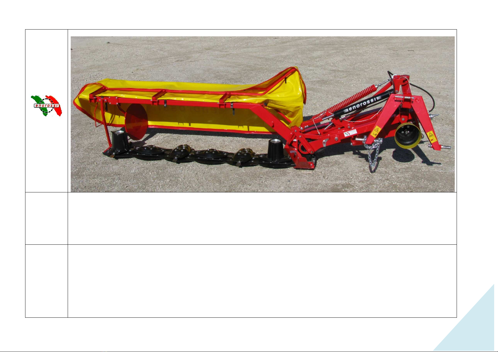
DISC MOWER DM SERIES
USER’S AND MAINTENANCE MANUAL
web: http://www.enorossi.it
DISC MOWER DM SERIES
4-5-6
LIGHT SERIES
USER’S AND MAINTENANCE MANUAL
ENOAGRICOLA ROSSI s.r.l.
06018 Calzolaro di Umbertide – Perugia – Italy
Tel. (39) 075-930 22 22 – Telefax (39) 075-930 23 28
web: http://www.enorossi.it
- http://www.enoagricolarossi.com
1
LIGHT SERIES

Section 1 – General information
................................
Section 2 – Use of the manual
................................
Section 3 – Machine assembly
................................
Section 4 –
Attachment of the machine to the tractor
Section 5 – Cardan shaft
................................
Section 6 – Transport position
................................
Section 7 –
Work position and adjustments
Section 8 –
Use of the mowing machine
Section 9 – Adjustments for operation
Section 10 –
Checks, maintenance, adjustments.
Section 11 - Lubrication
................................
Section 12 – Requesting spare parts
................................
This document is the property of ENOAGRICOLA ROSSI s.r.l.
No parts herein may be reproduced without prior consent from the Company Management
Any
infringements will be punished by law
ROTARY DM 4-5
U
SER’S AND MAINTENANCE MANUAL
Contents
................................
................................................................
................................
................................
................................................................
................................
................................
................................................................
................................
Attachment of the machine to the tractor
................................................................
................................
................................
................................................................
................................
................................
................................................................
................................
Work position and adjustments
................................................................
................................
Use of the mowing machine
................................................................
................................
................................................................................................
................................
Checks, maintenance, adjustments.
................................................................
................................
................................
................................................................
................................
................................
................................................................
................................
This document is the property of ENOAGRICOLA ROSSI s.r.l.
No parts herein may be reproduced without prior consent from the Company Management
.
infringements will be punished by law
.
SER’S AND MAINTENANCE MANUAL
Edition March 2010 -
Pagina 2 di 52
2
................................
...................................3
................................
.....................................4
................................
....................................6
................................
.................................15
................................
...........................................19
................................
...................................20
................................
...............................................22
................................
....................................................24
................................
.......................25
................................
......................................28
................................
.............................................32
................................
.........................36

Section 1 – General information
Assistance
For any needs, contact the machine dealer or the ENOAGRICOLA ROSSI Technical Office.
CE Marking
This mark certifies that the machine complies with the safety
Union.
CE Conformity declaration
conforms to the essential safety requirements established by Directives 89/392/EEC, 91/368/EEC,
The legal representative
ROTARY DM 4-5
U
SER’S AND MAINTENANCE MANUAL
For any needs, contact the machine dealer or the ENOAGRICOLA ROSSI Technical Office.
This mark certifies that the machine complies with the safety
requirements set by the European
ENOAGRICOLA ROSSI
06018 Calzolaro di Umbertide-Perugia-
Italy
ROTARY DISC MOWER
ENOAGRICOLA ROSSI srl
06018 Calzolaro di Umbertide-
Perugia
declares under its
exclusive responsibility that the machine
ROTARY DISC MOWER
Mod.........................
Series...........................
to which this declaration refers,
conforms to the essential safety requirements established by Directives 89/392/EEC, 91/368/EEC,
93/44/EEC, 93/68/EEC.
The legal representative
SER’S AND MAINTENANCE MANUAL
Edition March 2010 -
Pagina 3 di 52
3
For any needs, contact the machine dealer or the ENOAGRICOLA ROSSI Technical Office.
requirements set by the European
Italy
Perugia
-Italy
exclusive responsibility that the machine
conforms to the essential safety requirements established by Directives 89/392/EEC, 91/368/EEC,

Section 2 – Use of the manual
BEFORE INSTALLING AND USING THE MACHINE
OR BEFORE CARRYING OUT ANY OPERATION
READ CAREFULLY THE INSTRUCTIONS CONTAINED IN THIS MANUAL
This manual has been
written for your safety. It is an integral part of this machine and must be kept for reference at all
times, protecting it from moisture, neglect, and sunlight in order to prevent its deterioration
The manual is intended for: the machine users, the o
use, supervision, maintenance, and final dismantling.
The manual provides indications on the correct use of the machine, its technical features, and safety measures; this
manual,
in any case, can never replace an adequate experience of the user.
The manual also gives information for personnel training, for guiding maintenance operations, facilitating the request for
spare parts, and warning about remaining risks that could no
The manual reflects the state of the machine’s technical status as sold and cannot be considered inadequate if
subsequently updated on the basis of new experience
The company supplying the machine
obligation to update previous production and related manuals
N.B.
Enoagricola Rossi accepts no liability for
accordance with national and Community workplace safety requirements
required maintenance, unauthorized changes or repairs,
failure to f
ollow the instructions contained in this manual
ROTARY DM 4-5
U
SER’S AND MAINTENANCE MANUAL
BEFORE INSTALLING AND USING THE MACHINE
OR BEFORE CARRYING OUT ANY OPERATION
READ CAREFULLY THE INSTRUCTIONS CONTAINED IN THIS MANUAL
written for your safety. It is an integral part of this machine and must be kept for reference at all
times, protecting it from moisture, neglect, and sunlight in order to prevent its deterioration
The manual is intended for: the machine users, the o
wner, the safety supervisors, those in charge of handling, installation,
use, supervision, maintenance, and final dismantling.
The manual provides indications on the correct use of the machine, its technical features, and safety measures; this
in any case, can never replace an adequate experience of the user.
The manual also gives information for personnel training, for guiding maintenance operations, facilitating the request for
spare parts, and warning about remaining risks that could no
t be eliminated in the design phase.
The manual reflects the state of the machine’s technical status as sold and cannot be considered inadequate if
subsequently updated on the basis of new experience
.
The company supplying the machine
reserves
the right to make any changes to the product and its manual without the
obligation to update previous production and related manuals
.
Enoagricola Rossi accepts no liability for
damages resulting from improper use by untrained personnel
accordance with national and Community workplace safety requirements
, incorrect installation, serious deficiencies in the
required maintenance, unauthorized changes or repairs,
use of unauthorised spare parts, acts of God, or total or partial
ollow the instructions contained in this manual
.
SER’S AND MAINTENANCE MANUAL
Edition March 2010 -
Pagina 4 di 52
4
READ CAREFULLY THE INSTRUCTIONS CONTAINED IN THIS MANUAL
written for your safety. It is an integral part of this machine and must be kept for reference at all
times, protecting it from moisture, neglect, and sunlight in order to prevent its deterioration
.
wner, the safety supervisors, those in charge of handling, installation,
The manual provides indications on the correct use of the machine, its technical features, and safety measures; this
The manual also gives information for personnel training, for guiding maintenance operations, facilitating the request for
t be eliminated in the design phase.
The manual reflects the state of the machine’s technical status as sold and cannot be considered inadequate if
the right to make any changes to the product and its manual without the
damages resulting from improper use by untrained personnel
, use not in
, incorrect installation, serious deficiencies in the
use of unauthorised spare parts, acts of God, or total or partial

The machine has been designed in conformity with European machine safety standards and, in particular, the following
standards have been considered
1. EN 292/2 Ed. 1991:
Safety of machine. Fundamental
specifications and principles.
2. ISO 7000 Ed. 1994:
Safety decals to be used on machine
The machine must be used by operators who
1.
Have a good knowledge of safety standards and
2.
Are well informed on risks of this machine and dangerous areas and on the importance of not tampering with protection
guards.
3.
Have been well trained on how to operate the machine
4.
Will inform manufacturer of any malfunctioning
In the
event this manual is lost or damaged, a new copy may be requested from this address:
IMPORTANT!
If the machine is sold, please turn this manual over to the new owner.
ROTARY DM 4-5
U
SER’S AND MAINTENANCE MANUAL
The machine has been designed in conformity with European machine safety standards and, in particular, the following
standards have been considered
:
Safety of machine. Fundamental
concepts and general principles of mechanical design. Technical
Safety decals to be used on machine
.
The machine must be used by operators who
:
Have a good knowledge of safety standards and
regulations.
Are well informed on risks of this machine and dangerous areas and on the importance of not tampering with protection
Have been well trained on how to operate the machine
.
Will inform manufacturer of any malfunctioning
.
event this manual is lost or damaged, a new copy may be requested from this address:
ENOAGRICOLA ROSSI Srl
06018 Calzolaro di Umbertide – Perugia –Italy
Tel 075 / 930 22 22 Fax 075 / 930 23 28
If the machine is sold, please turn this manual over to the new owner.
SER’S AND MAINTENANCE MANUAL
Edition March 2010 -
Pagina 5 di 52
5
The machine has been designed in conformity with European machine safety standards and, in particular, the following
concepts and general principles of mechanical design. Technical
Are well informed on risks of this machine and dangerous areas and on the importance of not tampering with protection
event this manual is lost or damaged, a new copy may be requested from this address:

Section 3 – Machine assembly
To facilitate shipments of the machines, several parts have been disassembled to reduce the shipping dimensions. To
reassemble, proceed as follows:
•
Open the case and lay the mower disc bar flat as indicated in Fig. 1.
•
Turn the frame and the 3
as in Fig. 2
Fig. 1
ROTARY DM 4-5
U
SER’S AND MAINTENANCE MANUAL
To facilitate shipments of the machines, several parts have been disassembled to reduce the shipping dimensions. To
reassemble, proceed as follows:
Open the case and lay the mower disc bar flat as indicated in Fig. 1.
Turn the frame and the 3
rd
point using a lifting device (hoist, lift truck, etc.) and position the mower disc bar
Fig. 1
SER’S AND MAINTENANCE MANUAL
Edition March 2010 -
Pagina 6 di 52
6
To facilitate shipments of the machines, several parts have been disassembled to reduce the shipping dimensions. To
point using a lifting device (hoist, lift truck, etc.) and position the mower disc bar
Fig. 2

1
st
assembly –
assembly of the protection support.
Mount protection support A
(Fig. 3
connect the lifting rod hole to support
screws C(screw T.E. M12x5
0 and washer M12
2
nd
assembly –
assembly of the protection bar (only on DM
series).
Position the protection bar E
in support
F
(screw T.E. M10x35), six washers, and six self
DM-P series).
ROTARY DM 4-5
U
SER’S AND MAINTENANCE MANUAL
assembly of the protection support.
(Fig. 3
– Fig. 3/A) in gear case B; first of all,
connect the lifting rod hole to support
D (Fig. 3). Fasten the support with
0 and washer M12
Yand spacer J.
assembly of the protection bar (only on DM
-P
in support
A (Fig. 4) and fasten it with six screws
(screw T.E. M10x35), six washers, and six self
-locking nuts GM10 (only on
SER’S AND MAINTENANCE MANUAL
Edition March 2010 -
Pagina 7 di 52
7
Fig. 3/A
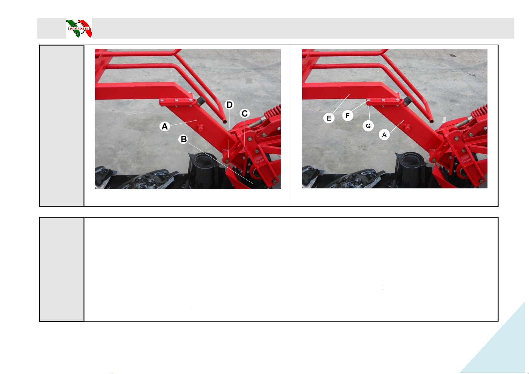
Fig. 3
3
rd
assembly –
support rod.
Mount support rod H
(Fig. 5), and fasten with screws
locking nut M10)
4
th
assembly –
assembly of the side rake disc.
Fasten rake disc unit Ion the
central
plate Z ( 115x95x10)
M
ake sure the rake disc does not touch the cone cover and blades. Observe the safety distance X= from 15 to 25 mm
(Fig. 6).
ROTARY DM 4-5
U
SER’S AND MAINTENANCE MANUAL
Fig. 3
support rod.
(Fig. 5), and fasten with screws
M(T.E. M12x80 + self locking nut
), and screws
assembly of the side rake disc.
central
bar M(Fig. 5). Fasten it using screws P
( T.E.M10x70 + self locking nut M10) and
ake sure the rake disc does not touch the cone cover and blades. Observe the safety distance X= from 15 to 25 mm
SER’S AND MAINTENANCE MANUAL
Edition March 2010 -
Pagina 8 di 52
8
Fig. 4
), and screws
N(T.E. M10x30
+ self
( T.E.M10x70 + self locking nut M10) and
ake sure the rake disc does not touch the cone cover and blades. Observe the safety distance X= from 15 to 25 mm
.

Fig. 5
5
th
assembly –
assembly of the internal cone disc.
Mount internal cone disc M
(Fig. 7)
6
th
assembly –
assembly of the lower slide and protection plate.
Lift the mower and mount the lower slide
locking nuts + washer Ø12
) and two screws
ROTARY DM 4-5
U
SER’S AND MAINTENANCE MANUAL
Fig. 6
assembly of the internal cone disc.
(Fig. 7)
so that the largest dimension is oriented perpendicular to that of the nearby disc.
assembly of the lower slide and protection plate.
Lift the mower and mount the lower slide
N(Fig. 8) and slide tip O
. Fasten them with four screws
) and two screws
Q(TTQS M10x25 + washer M10+ self
locking nut M10
SER’S AND MAINTENANCE MANUAL
Edition March 2010 -
Pagina 9 di 52
9
Fig. 6
so that the largest dimension is oriented perpendicular to that of the nearby disc.
. Fasten them with four screws
P(T.E. 12x30 + self-
locking nut M10
).
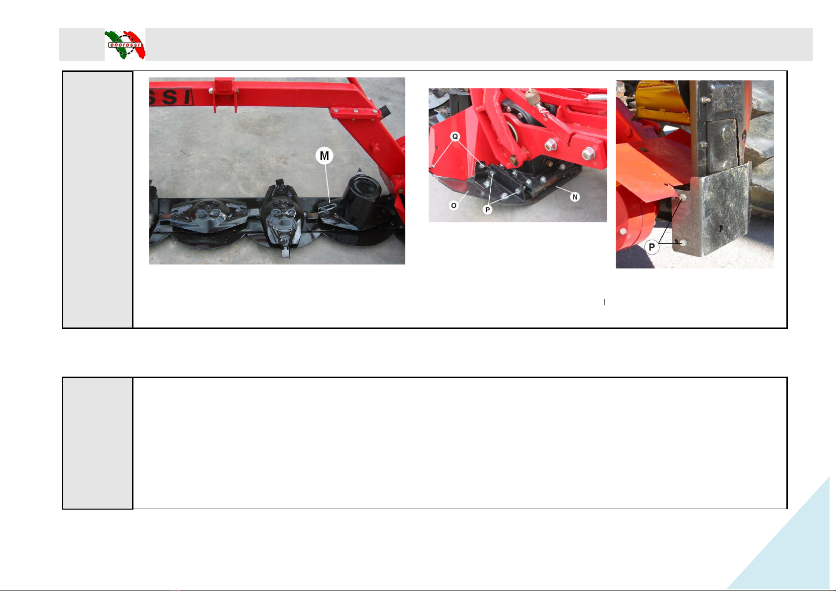
Fig. 7
7
th
assembly –
assembly of internal protective flap.
Mount flap R(Fig. 9)
protecting the gear case and fasten it with connecting bracket
washer M10 + washer +
self locking nut M10
starting to tighten them.
8
th
assembly –
assembly of the belt protection case.
Mount case U (Fig. 10)
, fasten with screws
ROTARY DM 4-5
U
SER’S AND MAINTENANCE MANUAL
Fig. 8
assembly of internal protective flap.
protecting the gear case and fasten it with connecting bracket
S
and three screws
self locking nut M10
). To facilitate assembly of flap R
, it is advisable to insert all screws before
assembly of the belt protection case.
, fasten with screws
V(T.E. M10x120), washers and self-
blocking nuts (M10).
SER’S AND MAINTENANCE MANUAL
Edition March 2010 -
Pagina 10 di 52
10
Fig. 8
and three screws
T
(TTQS M10x25 +
, it is advisable to insert all screws before
blocking nuts (M10).
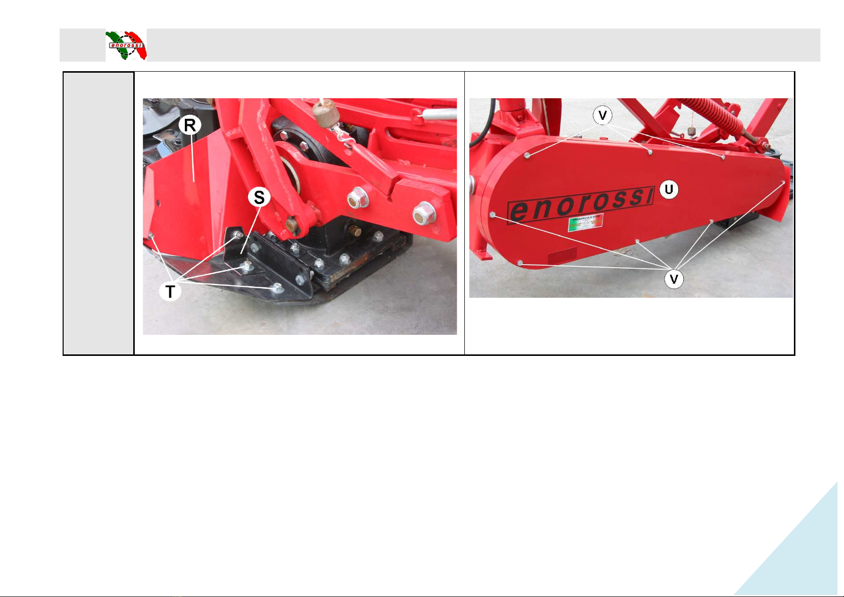
Fig. 9
ROTARY DM 4-5
U
SER’S AND MAINTENANCE MANUAL
Fig. 9
SER’S AND MAINTENANCE MANUAL
Edition March 2010 -
Pagina 11 di 52
11
Fig. 10

9
th
assembly –
compensating spring.
Hook spring W(Fig. 11) on pin
Y
To facilitate this operation, attach the machine to the tractor, lifting it until the support hole is aligned with pin
10
th
assembly –
assembly of the release cord.
Insert cord A (Fig. 12)
through ring
through ring E
and tie safety hook
Mount hydraulic pipe G
on the hydraulic piston, with the perforated screw, positioning the copper washers (Fig. 13).
Fig. 11
ROTARY DM 4-5
U
SER’S AND MAINTENANCE MANUAL
compensating spring.
Y
of the protection support and fast
en it with an elastic pin Ø 6x40
To facilitate this operation, attach the machine to the tractor, lifting it until the support hole is aligned with pin
assembly of the release cord.
through ring
B, then fasten the hook to safety hook C
. Close the hook with a pliers. Insert cord
and tie safety hook
C (Fig. 13), making a knot in the hole.
on the hydraulic piston, with the perforated screw, positioning the copper washers (Fig. 13).
Fig. 12
SER’S AND MAINTENANCE MANUAL
Edition March 2010 -
Pagina 12 di 52
12
en it with an elastic pin Ø 6x40
.
To facilitate this operation, attach the machine to the tractor, lifting it until the support hole is aligned with pin
Y(Fig. 11).
. Close the hook with a pliers. Insert cord
D
on the hydraulic piston, with the perforated screw, positioning the copper washers (Fig. 13).
Fig. 13
11
th
assembly –
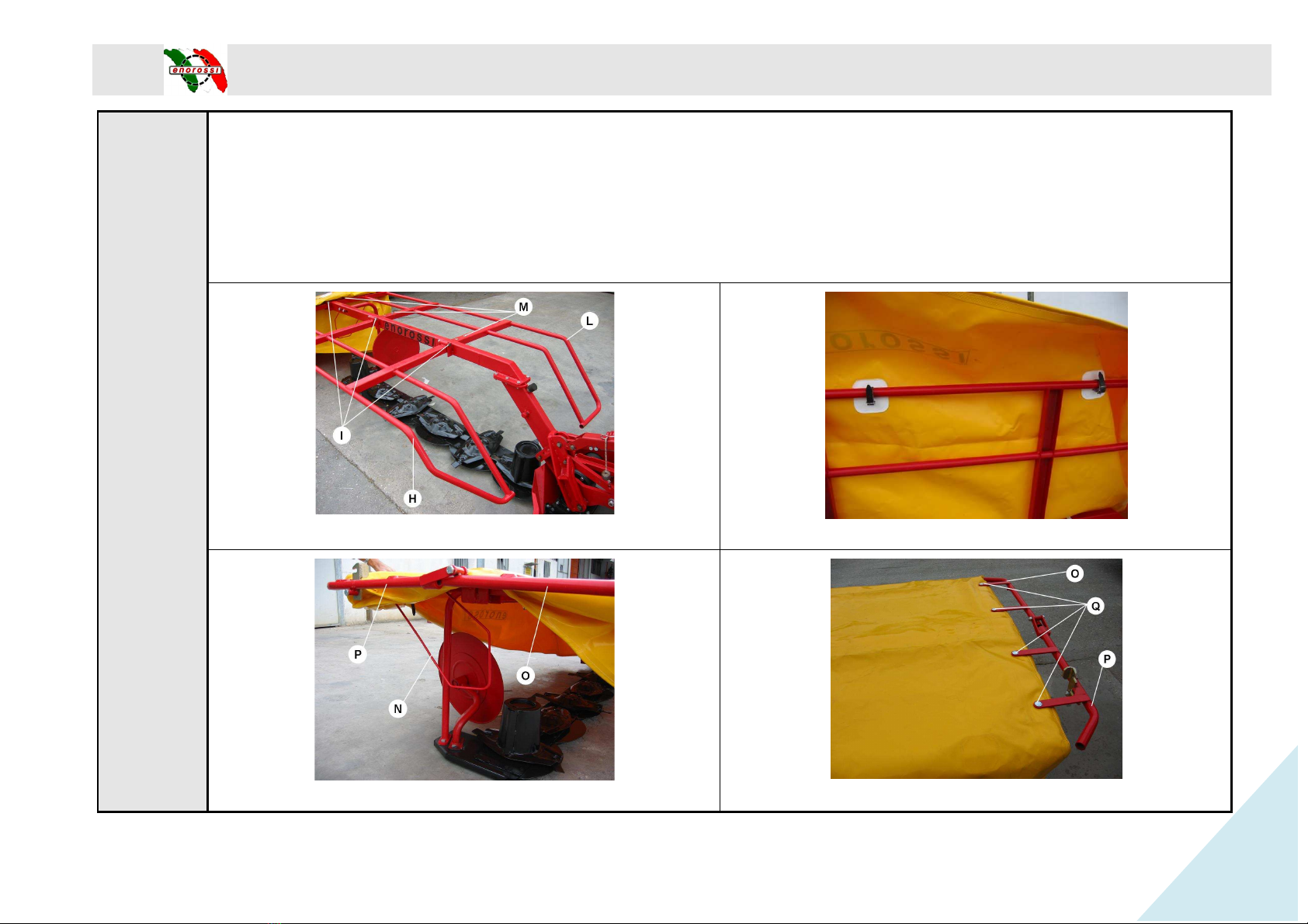
assembly of protection guards.
Mount front guard H(Fig. 14)
on the three hinges and fasten with screws
Mount rear guard L
with six screws
Assemble the protection guard frame and fasten it to the supporting structure using the ties found under the tarpaulin (Fig.
Assemble the protection rod for tarpaulin
Fasten rear handle Pwith screws
Q
Fig. 14
Fig. 16
ROTARY DM 4-5
U
SER’S AND MAINTENANCE MANUAL
assembly of protection guards.
on the three hinges and fasten with screws
I(T.E. M10x85
) and self
with six screws
M(TTQS M10x25) and self-locking nuts M10.
Assemble the protection guard frame and fasten it to the supporting structure using the ties found under the tarpaulin (Fig.
Assemble the protection rod for tarpaulin
N(Fig. 17)
and at the same time assemble (Fig. 16) front handle
Q
(TTQS M10x35), washers, and self-locking nuts M10.
Fig. 14
Fig. 16
SER’S AND MAINTENANCE MANUAL
Edition March 2010 -
Pagina 13 di 52
13
) and self
-locking nuts M10 + washer.
Assemble the protection guard frame and fasten it to the supporting structure using the ties found under the tarpaulin (Fig.
15).
and at the same time assemble (Fig. 16) front handle
Oand rear handle P.
Fig. 15
Fig. 17

12
th
assembly –
blade assembly.
Check the
rotation direction of the discs; each blade has an arrow indicating the rotation direction. After tightening the
screw and nut, make sure the blade can rotate fre
13
th
assembly –
assembly of the protective guard.
Insert the
guard into the power takeoff tube an
14
th
Insert pin A
Ø40x274 on left side
washers Ø24
Fig. 18
Free
Rotation
ROTARY DM 4-5
U
SER’S AND MAINTENANCE MANUAL
blade assembly.
rotation direction of the discs; each blade has an arrow indicating the rotation direction. After tightening the
screw and nut, make sure the blade can rotate fre
ely from the oval disc (Fig. 18).
assembly of the protective guard.
guard into the power takeoff tube an
d fasten with the band
screw T.E. M8x16 and washer M8x24
Ø40x274 on left side
; insert pin BØ40x219
on right side see fig. 19. Fasten the pins using nuts
Fig. 18
Rotation
SER’S AND MAINTENANCE MANUAL
Edition March 2010 -
Pagina 14 di 52
14
rotation direction of the discs; each blade has an arrow indicating the rotation direction. After tightening the
screw T.E. M8x16 and washer M8x24
(Fig. 19).
on right side see fig. 19. Fasten the pins using nuts
CM24 +
Fig. 19
Section 4 –
Attachment of the machine to the tractor
NB: The mower must be attached to a tractor with a power takeoff of 540
rpm and to a 3-
point attachment (Fig. 20).
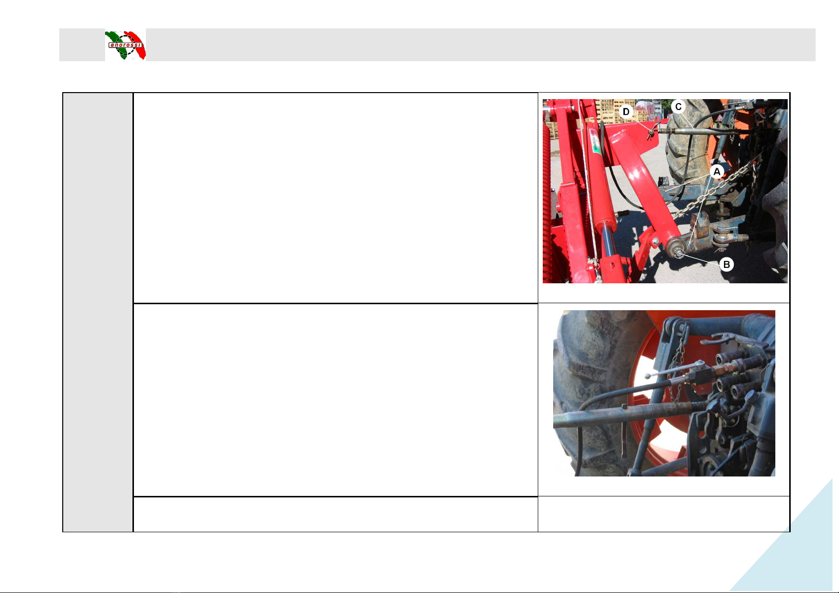
Instructions for attachment to the
1)
Insert the tractor’s lifting arms
fasten them with split pins.
2) Insert 3
rd
point C
and fasten it with pin
3)
Connect the hydraulic pipe of the piston to th
21)
ROTARY DM 4-5
U
SER’S AND MAINTENANCE MANUAL
Attachment of the machine to the tractor
NB: The mower must be attached to a tractor with a power takeoff of 540
point attachment (Fig. 20).
Instructions for attachment to the
tractor:
Insert the tractor’s lifting arms
A (Fig. 20) into attachment pins Band
and fasten it with pin
D(Fig. 20).
Connect the hydraulic pipe of the piston to th
e tractor’s distributor (Fig.
SER’S AND MAINTENANCE MANUAL
Edition March 2010 -
Pagina 15 di 52
15
Fig. 20
Fig. 21

4) Connect the tractor’s cardan shaft to the power takeoff of the mower;
use chains to prevent rotation of the protection pipe.
5) Lift the machine using the hydraulic lift; turn edge
6) IMPORTANT!!!
During work and transport, edge
turned upwards as in Fig. 23.
ROTARY DM 4-5
U
SER’S AND MAINTENANCE MANUAL
4) Connect the tractor’s cardan shaft to the power takeoff of the mower;
use chains to prevent rotation of the protection pipe.
5) Lift the machine using the hydraulic lift; turn edge
Eupwards (Fig. 22)
During work and transport, edge
Emust always
be
SER’S AND MAINTENANCE MANUAL
Edition March 2010 -
Pagina 16 di 52
16
Fig. 22
Fig. 23
7)
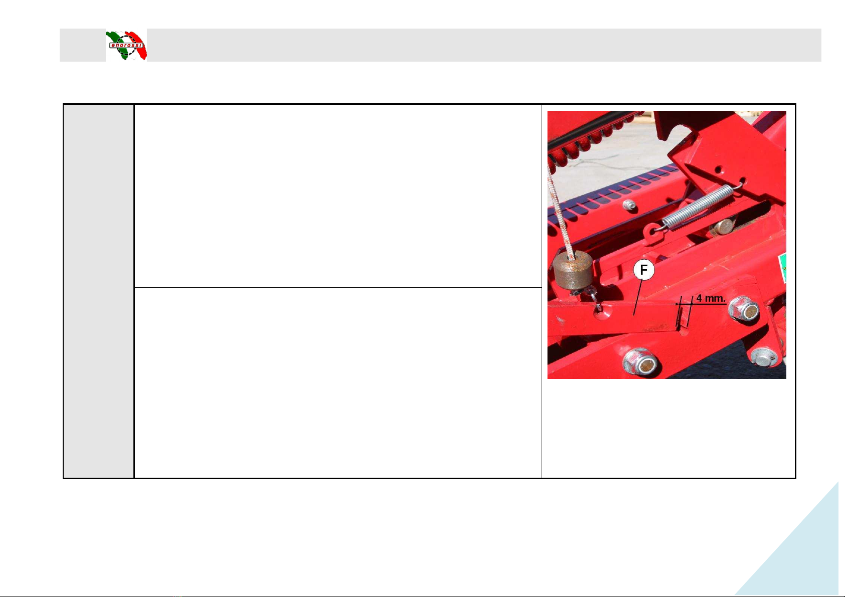
ADJUSTMENT OF FRAME HEIGHT FROM THE GROUND.
A -
for tractors equipped with hydraulic lift position control:
Position the tractor on level ground and lower the hydraulic lift until the
lifting lever F
is positioned at a distance of 4 mm from the edge, as shown
in Fig. 24.
After adjusting the height of the mower frame, set the lift control
tractor driver’s seat. In this case it is not necessary to use the limiting chain
supplied with the machine.
ROTARY DM 4-5
U
SER’S AND MAINTENANCE MANUAL
ADJUSTMENT OF FRAME HEIGHT FROM THE GROUND.
for tractors equipped with hydraulic lift position control:
Position the tractor on level ground and lower the hydraulic lift until the
is positioned at a distance of 4 mm from the edge, as shown
After adjusting the height of the mower frame, set the lift control
from the
tractor driver’s seat. In this case it is not necessary to use the limiting chain
SER’S AND MAINTENANCE MANUAL
Edition March 2010 -
Pagina 17 di 52
17
Fig. 24

B –
for tractors not equipped with hydraulic lift position control:
The chain supplied with the machine must be used.
Fasten bracket G
(Fig. 25) and the limiting chain
free holes of the tractor’s third point.
Lower the machine to work position, until lifting lever
distance of 4 mm from the edge, as shown in Fig. 24. Limiting
must be taut (Fig. 25
), and the lifting lever must be at a distance of 4 mm.
as per Fig. 24.
To be able to always recognize this position, mark the chain ring that will
be hooked with bracket G.
ROTARY DM 4-5
U
SER’S AND MAINTENANCE MANUAL
for tractors not equipped with hydraulic lift position control:
The chain supplied with the machine must be used.
(Fig. 25) and the limiting chain
Hsupplied, to one of the
free holes of the tractor’s third point.
Lower the machine to work position, until lifting lever
F is positioned at a
distance of 4 mm from the edge, as shown in Fig. 24. Limiting
chain H
), and the lifting lever must be at a distance of 4 mm.
To be able to always recognize this position, mark the chain ring that will
SER’S AND MAINTENANCE MANUAL
Edition March 2010 -
Pagina 18 di 52
18
Fig. 25

Section 5 – Cardan shaft
ROTARY DM 4-5
U
SER’S AND MAINTENANCE MANUAL
The cardan shaft supplied with the mower is of the correct size for coupling
with most tractors on the market.
In any case, before starting work for the first time, it is advisable to check its
length.
If adaptation is required, proceed as follows:
Important!
Use only the cardan shaft supplied or recommended, otherwise any warranty
claim or request will be considered null and void.
If the cardan shaft is too long, open the two halves and overlap them; this way
it will be possible to determine how much longer it is in cm.
Cut both tubes of the internal and external cardan shaft to the same length, as
well as their guards.
Clean the cut edges of the tubes with a file, grease them, and reclose the
cardan shaft.
Important!
The maximum work length (L1)
must allow an overlapping of the tubes equal to
half the length of the closed cardan shaft (min. _X).
Always make sure that the cardan shaft is correctly tightened before starting
work
Support chain
Use the chain to prevent rotation of the protection tube.
Make sure that the chain does not hamper the side movements of the cardan
shaft.
SER’S AND MAINTENANCE MANUAL
Edition March 2010 -
Pagina 19 di 52
19
The cardan shaft supplied with the mower is of the correct size for coupling
In any case, before starting work for the first time, it is advisable to check its
Use only the cardan shaft supplied or recommended, otherwise any warranty
If the cardan shaft is too long, open the two halves and overlap them; this way
Cut both tubes of the internal and external cardan shaft to the same length, as
Clean the cut edges of the tubes with a file, grease them, and reclose the
must allow an overlapping of the tubes equal to
Always make sure that the cardan shaft is correctly tightened before starting
Make sure that the chain does not hamper the side movements of the cardan

Section 6 – Transport position
Before moving the mower into transport position, send away
all persons who may be in the manoeuvring area.
To
position for road transport or for moving from one field to
another, carry out the following operations:
1)
Disconnect the tractor power takeoff, and make sure the
discs have stopped rotating.
2) Turn front guard I
backward until the fastening point with
hook L(Fig. 26).
3) Lift the bar using the tractor’s hydraulic lift, positioning
lower slide Mat about 15-
20 cm from the ground (Fig. 27).
4) Edge E
must be turned upwards (Fig. 22
15).
ROTARY DM 4-5
U
SER’S AND MAINTENANCE MANUAL
Before moving the mower into transport position, send away
all persons who may be in the manoeuvring area.
position for road transport or for moving from one field to
another, carry out the following operations:
Disconnect the tractor power takeoff, and make sure the
discs have stopped rotating.
backward until the fastening point with
3) Lift the bar using the tractor’s hydraulic lift, positioning
20 cm from the ground (Fig. 27).
must be turned upwards (Fig. 22
– Fig. 23 Pag.
SER’S AND MAINTENANCE MANUAL
Edition March 2010 -
Pagina 20 di 52
20
Fig. 26
Fig. 27
This manual suits for next models
3
Table of contents
Other enorossi Farm Equipment manuals

enorossi
enorossi G4V-3P User manual

enorossi
enorossi 16 Series Operating instructions

enorossi
enorossi ENODUO TRACER 780 User manual

enorossi
enorossi ENODUO 610 User manual

enorossi
enorossi ENOSPE US User manual

enorossi
enorossi RAKE CADDY Series Operating instructions

enorossi
enorossi EASY RAKE 10 User manual

enorossi
enorossi RT7 User manual

enorossi
enorossi DR 420 4R User manual

enorossi
enorossi G2 Series User manual


