Worksaver SSGB-8B Owner's manual

Safety Instructions Assembly & Mounting
Tractor Preparation Maintenance
Operating Instructions Repair Parts
SKID STEER MOUNTED
GRADER BLADE
OWNER’S/
OPERATOR’S
MANUAL
MODEL NO.
SSGB-8%
CAUTION
For Safe Operation
Read Rules And
Instructions Carefully
SINO LEEINGLES, PIDA AYUDA
A AIGUIEN QUE SI LO LEA
PARA QUE LE TRADUZCA LAS
MEDIDAS DE SEGURIDAD.
CAUTION
THE FOLLOWING SAFETY PRECAUTIONS SHOULD BE THOROUGHLY UNDERSTOOD
BEFORE ATTEMPTING TO BEGIN ASSEMBLING THIS MACHINE
1. Select an area for assembly that is clean and free of any
debris which might cause persons working on the
assembly to trip.
2. Do not lift heavy parts or assemblies. Use crane, jack,
tackle, fork trucks or other mechanical devices.
3. Preview the assembly instructions in your operator’s
manual before proceeding further.
4. If the assembly instructions call for parts or assemblies to
be blocked up, use only blocking material that is in good
condition and is capable of handling the weight of the
assembly to be blocked. Also insure that the blocking
material is on a clean, dry surface.
5. Never put hands, or any part of body, under blocked up
assemblies if at all possible.
6. After completing assembly, thoroughly inspect the
machine to be sure that all nuts, bolts, hydraulic fittings
or any other fastened assemblies have been thoroughly
tightened.
7. Before operating the machine, thoroughly read the
operation section of your operator’s manual.
8. Before operating, read the maintenance section of your
operator’s manual to be sure that any parts requiring
lubrication, such as gearboxes, are full, to avoid any
possible damage.
9. Before operating equipment – If you have any
questions regarding the proper assembly or
operation, contact your dealer or representative.


1
TO THE OWNER:
Read this manual before using your Grader Blade. This manual is provided to give you the necessary operat-
ing and maintenance instructions for keeping your Grader Blade in top operating condition. Please read this
manual thoroughly. Understand what each control is for and how to use it. Observe all safety signs on the machine
and noted throughout the manual for safe operation of implement. Keep this manual handy for ready reference.
Like all mechanical products, it will require cleaning and upkeep. Lubricate the Grader Blade as specified.
Use only genuine Worksaver, Inc. service parts. Substitute parts will void the warranty and may not meet
standards required for safe and satisfactory operation. Record the model and serial number of your Grader Blade
here:
Model:________________________________________ Serial Number:_______________________________
RETAIL CUSTOMER’S RESPONSIBILITY
It is the Retail Customer and/or Operator’s responsibility to read the Operator’s Manual, to operate, lubri-
cate, maintain, and store the product in accordance with all instructions and safety procedures. Failure
of the operator to read the Operator’s Manual is a misuse of this equipment.
It is the Retail Customer and/or Operator’s responsibility to inspect the product and to have any part(s)
repaired or replaced when continued operation would cause damage or excessive wear to other parts or
cause a safety hazard.
It is the Retail Customer’s responsibility to deliver the product to the authorized Worksaver Dealer, from
whom he purchased it, for service or replacement of defective parts which are covered by warranty.
Repairs to be submitted for warranty consideration must be made within forty-five (45) days of failure.
It is the Retail Customer’s responsibility for any cost incurred by the Dealer for traveling to or hauling
of the product for the purpose of performing a warranty obligation or inspection.
SINO LEEINGLES, PIDA AYUDA A
AIGUIEN QUE SI LO LEA PARA QUE
LE TRADUZCA LAS MEDIDAS DE
SEGURIDAD.
STATEMENT
OF POLICY
It is the policy of Worksaver,
Inc. to improve its products
where it is possible and practical
to do so. Worksaver, Inc.
reserves the right to make
changes or improvements in
design and construction at any
time, without incurring the obliga-
tion to make these changes on
previously manufactured units.
TABLE OF CONTENTS
WARRANTY . . . . . . . . . . . . . . . . . . . . . . . . . . . . . . . . . . . . . . . 2
SAFETY INFORMATION . . . . . . . . . . . . . . . . . . . . . . . . . . . . . 3
SAFETY SIGNS . . . . . . . . . . . . . . . . . . . . . . . . . . . . . . . . 11 - 12
PREPARATION INSTRUCTIONS . . . . . . . . . . . . . . . . . . . 13 - 14
OPERATING INSTRUCTIONS . . . . . . . . . . . . . . . . . . . . . 15 - 16
SERVICE & MAINTENANCE . . . . . . . . . . . . . . . . . . . . . . 17 - 18
TROUBLE-SHOOTING . . . . . . . . . . . . . . . . . . . . . . . . . . . 19 - 20
PARTS LISTS . . . . . . . . . . . . . . . . . . . . . . . . . . . . . . . . . . 21 - 24
WIRING & ELECTRICAL SCHEMATIC . . . . . . . . . . . . . . 25 - 26
END PLATE OPTION . . . . . . . . . . . . . . . . . . . . . . . . . . . . . . . . 27
LASER POLE OPTION . . . . . . . . . . . . . . . . . . . . . . . . . . . . . . 28
SPECIFICATIONS . . . . . . . . . . . . . . . . . . . . . . . . . . . . . . . . . . 29
BOLT TORQUE CHART . . . . . . . . . . . . . . . . . . . . . . . . . . . . . . 30

2
LIMITED WARRANTY
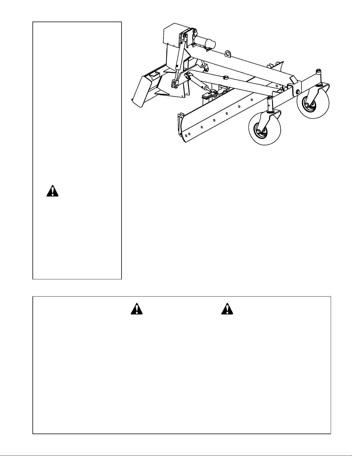
Worksaver warrants to the original purchaser of any new Grader Blade Model SSGB-%, that the equipment
be free from defects in material and workmanship for a period of TWELVE (12) MONTHS COMMENCING ON
THE DATE OF DELIVERY OF THE PRODUCT TO THE ORIGINAL PURCHASER.This warranty will apply if
notified to Worksaver, Inc.within thirty (30) days after such defect is discovered.
The warranty registration must be completed and returned to Worksaver, Inc.
Replacement or repair parts installed in the equipment covered by this warranty are warranted for ninety (90)
days from the date of purchase of such part or to the expiration of the applicable new equipment warranty
period, whichever occurs later.
Such parts shall be provided at no cost to the user during regular working hours. Worksaver reserves the right
to inspect any equipment or parts which are claimed to have been defective in material or workmanship.
This warranty is extended solely to the original purchaser of the product. Should the original purchaser sell or
otherwise transfer this product to a third party, this warranty does not transfer to the third party purchaser in
any way. There are no third party beneficiaries of this warranty.
DISCLAIMER OF IMPLIED WARRANTIES & CONSEQUENTIAL DAMAGES
Worksaver shall not be liable for any incident or consequential losses, damages or expenses, arising directly
or indirectly from the product, whether such claim is based upon breach of contract, breach of warranty,
negligence, strict liability in tort or any other legal theory.
Worksaver’s obligation under this warranty, to the extent allowed by law, is in lieu of all warranties, implied or
expressed, including implied warranties of merchantability and fitness for a particular purpose and any liabili-
ty for incidental and consequential damages with respect to the sale or use of the items warranted. Such
incidental and consequential damages shall include but not be limited to: transportation charges other than
normal freight charges; cost of installation other than cost approved by Worksaver; duty; taxes; charges for
normal service or adjustments; loss of crops or any other loss of income; rental of substitute equipment,
expenses due to loss, damage, detention or delay in the delivery of equipment or parts resulting from acts
beyond the control of Worksaver.
THIS WARRANTY SHALL NOT APPLY:
1. To vendor items which carry their own warranties, such as hydraulic cylinders, tires, and laser control
systems.
2. If the unit has been subjected to misapplication, abuse, misuse, negligence, fire or other accident.
3. If parts not made or supplied by Worksaver have been used in connection with the unit, if, in sole judge-
ment of Worksaver such use affects its performance, stability, or reliability.
4. If the unit has been altered or repaired outside of an authorized Worksaver dealership in a manner which,
in the sole judgement of Worksaver affects its performance, stability or reliability.
5. To normal maintenance service and normal replacement items such as gearbox lubricant, hydraulic fluid,
worn blades, or to normal deterioration of such things as hoses and exterior finish, due to use or exposure.
6. To expendable or wear items such as cutting edge, plow bolts, springs and other items that in the
company’s sole judgement is a wear item.
NO EMPLOYEE OR REPRESENTATIVE OF WORKSAVER IS AUTHORIZED TO CHANGE THIS
WARRANTY IN ANY WAY OR GRANT ANY OTHER WARRANTY UNLESS SUCH CHANGE IS MADE IN
WRITING AND SIGNED BY WORKSAVER’S SERVICE MANAGER, POST OFFICE BOX 100, LITCHFIELD,
ILLINOIS 62056-0100.
This warranty is subject to the warranty registration being submitted within sixty (60) days after
purchase. For warranty services, contact your selling dealer.

3
To the Owner/Operator/Dealer
All implements with moving parts are potentially hazardous. There is no substitute for a cautious, safe-minded opera-
tor who recognizes the potential hazards and follows reasonable safety practices. The manufacturer has designed this
implement to be used with all its safety equipment properly attached to minimize the chance of accidents.
BEFORE YOU START!!
Read the safety messages on the implement and shown in your manual.
Observe the rules of safety and common sense!
THIS SAFETY ALERT SYMBOL IDENTIFIES IMPORTANT
SAFETY WARNING MESSAGES. CAREFULLY READ EACH
WARNING MESSAGE THAT FOLLOWS. FAILURE TO
UNDERSTAND AND OBEY A SAFETY WARNING, OR
RECOGNIZE A SAFETY HAZARD, COULD RESULT IN AN
INJURY OR DEATH TO YOU OR OTHERS AROUND YOU.
THE OPERATOR IS ULTIMATELY RESPONSIBLE FOR THE
SAFETY OF HIMSELF, AS WELL AS OTHERS, IN THE
OPERATING AREA OF THE SKID STEER AND ATTACHED
EQUIPMENT.
IMPORTANT SAFETY INFORMATION!
Working with unfamiliar equipment can lead to careless injuries. Read this manual, and the manual for your tractor,
before assembly or operating, to acquaint yourself with the machines. It is the implement owner’s responsibility, if this
machine is used by any person other than yourself, is loaned or rented, to make certain that the operator, prior to
operating:
1. Reads and understands the operator’s manuals.
2. Is instructed in safe and proper use.
The use of this equipment is subject to certain hazards which cannot be protected against by mechanical
means or product design. All operators of this equipment must read and understand this entire manual,
paying particular attention to safety and operating instructions, prior to using. If there is something in this
manual you do not understand, ask your supervisor, or your dealer, to explain it to you.
THIS SYMBOL MEANS
–A
TTENTION!
– BECOME ALERT!
– YOUR SAFETY IS INVOLVED!
UNDERSTAND SIGNAL WORDS
Note the use of the signal words DANGER, WARNING
and CAUTION with the safety messages. The
appropriate signal word for each has been selected
using the following guidelines:
DANGER: Indicates an imminently hazardous situation
that, if not avoided, will result in death or serious injury.
This signal word is to be limited to the most extreme
situations typically for machine components which, for
functional purposes, cannot be guarded.
If you have questions not answered in this manual or require additional copies or the manual is damaged, please
contact your dealer or the manufacturer directly.
WARNING: Indicates a potentially hazardous sit-
uation that, if not avoided, could result in death
or serious injury, and includes hazards that are
exposed when guards are removed. It may also
be used to alert against unsafe practices.
CAUTION: Indicates a potentially hazardous sit-
uation that, if not avoided, may result in minor or
moderate injury. It may also be used to alert
against unsafe practices.

4
SAFETY INSTRUCTIONS (continued)
Safety of the operator is one of the main concerns in designing and developing a new piece of equipment.
Designers and manufacturers build in as many safety features as possible. However, every year many
accidents occur which could have been avoided by a few seconds of thought and a more careful approach to
handling equipment.You, the operator, can avoid many accidents by observing the following precautions in this
section. To avoid personal injury, study the following precautions and insist those working with you, or for you,
follow them.
In order to provide a better view, certain photographs or illustrations in this manual may show an assembly with
a safety shield removed. However, equipment should never be operated in this condition. Keep all shields in
place. If shield removal becomes necessary for repairs, replace the shield prior to use.
Do not paint over, remove or deface any safety signs or warning signs on your equipment. Observe all safety
signs and practice the instruction on them.
Never exceed the limits of a piece of machinery. If its ability to do a job, or to do so safely, is in question –
DON’T TRY IT.
Do not modify the equipment in any way. Unauthorized modification may impair the function and/or safety and
could affect the life of the equipment.
In addition to the design and configuration of this implement, including Safety Signs and Safety Equipment,
hazard control and accident prevention are dependent upon the awareness, concern, prudence, and proper
training of personnel involved in the operation, transport, maintenance, and storage of the machine. Refer also
to Safety Messages and Operation Instructions in each of the appropriate sections of the Skid Steer and
Attachment Manuals. Pay close attention to the Safety Signs affixed to the Skid Steer and the Attachment.
Replace any CAUTION, WARNING, DANGER or instruction safety sign that is not readable or is missing.
Location of such safety signs is indicated in this booklet.
Never use alcoholic beverages or drugs which can hinder alertness or coordination while operating this
equipment. Consult your doctor about operating this machine while taking prescription medications.
Review the safety instructions with all users annually.
This equipment is dangerous to children and persons unfamiliar with its operation. The operator should be a
responsible adult familiar with farm machinery and trained in this equipment’s operations. Do not allow per-
sons to operate or assemble this unit until they have read this manual and have developed a thorough
understanding of the safety precautions and of how it works.
EQUIPMENT SAFETY GUIDELINES

5
SAFETY INSTRUCTIONS (continued)
Keep safety signs clean and legible at all times.
Replace safety signs that are missing or have become illegible.
Replaced parts that displayed a safety sign should also display the current sign.
Safety signs are available from your Distributor or Dealer Parts Department or the factory.
Be sure that the installation area is clean and dry. Be sure temperature is above 50°F (10°C).
Decide on the exact position before you remove the backing paper.
Remove the smallest portion of the split backing paper. Align the sign over the specified area and carefully
press the small portion with the exposed sticky backing in place.
Slowly peel back the remaining paper and carefully smooth the remaining portion of the sign in place. Small
air pockets can be pierced with a pin and smoothed out using the piece of sign backing paper.
How to Install Safety Signs:
SAFETY SIGNS
Safety is a primary concern in the design and manufacture of our products. Unfortunately, our efforts to
provide safe equipment can be wiped out by a single careless act of an operator. It is the operator’s respon-
sibility to read and understand ALL Safety and Operating instructions in the manual and to follow these.
Accidents can be avoided.
In addition to the design and configuration of equipment, hazard control and accident prevention are
dependent upon the awareness, concern, prudence and proper training of personnel involved in the operation,
transport, maintenance and storage of equipment.
Know your controls and how to stop skid steer, engine, and attachment quickly in an emergency. Read this
manual and the one provided with your skid steer.
Train all new personnel and review instructions frequently with existing workers. A person who has not read
and understood all operating and safety instructions is not qualified to operate the machine. An untrained
operator exposes himself and bystanders to possible serious injury or death.
Working with unfamiliar equipment can lead to careless injuries. Read this manual, and the manual for your
skid steer, before assembly or operating, to acquaint yourself with the machines. It is the owner’s responsibil-
ity, if this machine is used by any person other than yourself, is loaned or rented, to make certain that the
operator, prior to operating:
1. Reads and understands the operator’s manuals.
2. Is instructed in safe and proper use.
SAFETY TRAINING
Do not allow children to operate this machine.

6
SAFETY INSTRUCTIONS (continued)
Avoid uneven and rough terrain. DO NOT operate near drop off, ditches, or embankments. Unit can suddenly
turn over if a wheel is over the edge of a cliff or ditch, or if an edge caves in.
Take all possible precautions when leaving unit unattended: Disengage hydraulic power, set parking brake,
stop engine and remove key from ignition. Park in level area.
Grader blade operating power is supplied from skid steer hydraulic system. Refer to your skid steer manual for
hydraulic engagement and disengagement instructions. Know how to stop skid steer and grader controls
quickly in case of an emergency.
Grader blade should be on the ground before engaging hydraulic power and be sure that no one is near the
machine. When engaging hydraulic system, the RPM should always be low.
Be certain the skid steer is in neutral or park position before starting engine.
Do not leave the skid steer or the attachment unattended with the engine running.
The use of this equipment is subject to certain hazards which cannot be protected against by mechanical
means or product design. All operators of this equipment must read and understand this entire manual, pay-
ing particular attention to safety and operating instructions, prior to using. If there is something in this manu-
al you do not understand, ask your supervisor, or your dealer, to explain it to you.
Most accidents occur because of neglect or carelessness. Keep all helpers and bystanders at least twenty (20)
feet from an operating grader. Only properly trained people should operate this machine.
STARTING AND STOPPING SAFETY
OPERATIONAL SAFETY
Do not walk or work under a raised skid steer attachment unless it is securely blocked or held in position. Do
not depend on the hydraulic system to hold the skid steer attachment in place.
A heavy load can cause instability of the skid steer. Use extreme care during travel. Slow down on turns and
watch out for bumps. The skid steer may need additional counter-weights to counter-balance the weight of the
grader blade attachment.
Never use alcoholic beverages or drugs which can hinder alertness or coordination while operating this
equipment. Consult your doctor about operating this machine while taking prescription medications.
Never permit any person other than the operator to ride or board the skid steer or grader blade attachment at
any time. ALLOW NO RIDERS!

7
SAFETY INSTRUCTIONS (continued)
Consult local utility companies to make certain there are no buried gas lines, electrical cables, etc., in the work
area before beginning operation.
Use extreme care and maintain minimum ground speed when transporting on hillside, over rough ground and
when operating close to ditches or fences. Be careful when turning sharp corners.
Inspect the entire machine periodically as indicated in the Maintenance Section of this manual. Look for loose
fasteners, worn or broken parts and/or shields. Make sure all pins have cotter pins and washers. Serious injury
may occur from not maintaining this machine in good working order.
Avoid sudden starts and stops while traveling up or downhill. Avoid parking on a slope.
Always drive down slopes; never across the face. Avoid operation on steep slopes. Slow down on sharp turns
and slopes to prevent tipping and/or loss of control. Avoid slopes when surface is wet, slippery grass or soil.
Be careful when changing directions on slopes. Do not start or stop suddenly on slopes.
Keep work area clear of all debris. Debris could damage the unit. Never assume an area is clear. ALWAYS
CHECK.
OPERATIONAL SAFETY (continued)
Before you operate the grader blade, check over all pins, bolts and connections to be sure all are securely in
place. Replace any damaged or worn parts immediately.
When maneuvering close to buildings or passing through narrow areas, be sure to allow sufficient clearance
for the skid steer and attachment. Drive slowly.
Keep alert and watch the rear as well as the front when working with the grader blade. Watch for traffic when
operating along streets or curbs.
Most accidents occur because of neglect or carelessness. Keep all helpers and bystanders at a safe distance.
Make sure children are out of work area and under watchful care of a responsible adult.
Beware of low electrical wires if grader blade attachment is raised with skid steer loader. Serious injury or death
can result if contact is made. Beware of lift clearance when raising grader blade to maximum height.

8
SAFETY INSTRUCTIONS (continued)
OPERATIONAL SAFETY (continued)
Stop skid steer loader gradually when lowering or lifting loads. Operate skid steer and grader blade controls
smoothly, avoid jerky operation.
Operate grader blade from operator’s seat only. Remain at controls until operating cycle is complete.
Allow for additional length of loader arms and attachment on skid steer while turning.
Be sure that people, livestock, or pets are not standing near the machine while operating.
Avoid excessive speed during operation.
Do not lift or carry anyone on loader or in bucket or on attachment. Do not use grader blade for a work platform.
ALWAYS lower loader and grader blade attachment to the ground or block securely before performing any
maintenance work.
Use extra care when loading or unloading grader blade onto trailer or truck. NEVER secure rods or linkages
on unit that could be damaged when transporting.
Stay alert for holes, rocks and roots in the terrain and other hidden hazards. Keep away from drop-offs.
Before operating equipment: if you have any questions regarding the proper assembly or operation, contact
your dealer or representative.

9
SAFETY INSTRUCTIONS (continued)
Make sure there is plenty of ventilation. Never operate the engine of the vehicle in a closed building. The
exhaust fumes may cause asphyxiation.
Before working on this machine, drive to a level area, relieve hydraulic pressure, lower implement (or if work-
ing underneath, raise and block securely), shut off the engine, set the brakes, and remove the ignition keys.
Relieve hydraulic pressure prior to doing any maintenance.
Never work under equipment unless it is blocked securely. Never depend on hydraulic system to keep
implement in raised position.
Always use personal protection devices such as eye, hand and hearing protectors, when performing any
service or maintenance.
Never use your hands to locate a hydraulic leak on attachments. Use a small piece of cardboard or wood.
Hydraulic fluid escaping under pressure can penetrate the skin.
Openings in the skin and minor cuts are susceptible to infection from hydraulic fluid. If injured by escaping
hydraulic fluid, see a doctor at once. Gangrene and death can result. Without immediate medical treatment,
serious infection and reactions can occur.
Keep all persons away from operator control area while performing adjustments, service, or maintenance.
Periodically tighten all bolts, nuts and screws and check that all cotter pins are properly installed to ensure unit
is in a safe condition.
When completing a maintenance or service function, make sure all safety shields and devices are installed
before placing unit in service.
Always use two people to handle heavy, unwieldy components during assembly, installation, removal, or
moving the grader blade attachment
MAINTENANCE SAFETY
Check to ensure all safety signs are installed and in good condition. (See safety sign section for location
drawing.)
Good maintenance is your responsibility. Poor maintenance is an invitation to trouble.

10
SAFETY INSTRUCTIONS (continued)
Comply with state and local laws governing highway safety and movement of machinery on public roads.
The use of flashing amber lights is acceptable in most localities. However, some localities prohibit their use.
Local laws should be checked for all highway lighting and marking requirements.
Always be sure the attachment is in the proper raised position for transport.
Reduce speed when transporting mounted attachments to avoid bouncing and momentary loss of steering
control.
If grader unit is loaded on a truck or trailer for transport, make sure unit is securely tied down. NEVER tie to
rods or linkage parts that could be damaged.
Plan your route to avoid heavy traffic.
Do not drink and drive!
Watch for traffic when operating near or crossing roadways.
Never allow riders on either skid steer or attachment. Falling off can kill.
Be a safe and courteous driver. Always yield to oncoming traffic in all situations, including narrow bridges, inter-
sections, etc.
TRANSPORT SAFETY
Store the unit in an area away from human activity. Do not permit children to play on or around the stored unit.
Make sure all parked machines are on a hard, level surface and engage all safety devices. Storage location
should be level and solid to make connecting and unconnecting to skid steer easy.
If blocking is used, make sure it is solid and secure before leaving area.
STORAGE SAFETY

11
SAFETY SIGNS
REMEMBER: If Safety Signs have been damaged, removed, become illegible or parts replaced without Signs, new
Safety Signs must be applied. New Safety Signs are available from your authorized distributor or factory.
WARNING
Stand clear 101027

SAFETY SIGN LOCATION
The types of safety signs and locations on the equipment are shown in the illustration
below. Good safety requires that you familiarize yourself with various safety signs, the type
of warning and the area, or particular function related to that area, that requires your
SAFETY AWARENESS.
Ref. Part No. Description No.
No. Req’d.
1 101289 Safety Sign – Warning (Avoid Serious Injury) 1
2 101290 Safety Sign – Caution (Getting On and Off) 1
3 101288 Safety Sign – Warning (Crushing and Pinching) 1
4 101122 Safety Sign – Warning (High-Pressure Fluid) 1
5 101027 Safety Sign – Warning (Stand Clear) 2
6 101291 Safety Sign – Caution (No Step) 1
The model and serial number plate is located on the right side of the vertical
part of the main frame.
The serial number is also stamped into the top cross tube of the skid steer
mounting frame.
12

13
CAUTION!
Be sure your skid steer is in good condition. Read
all the safety precautions and make sure all skid
steer operators are familiar with the safety rules of
operation.
Refer to the “exploded view” of the skid steer mounted
grader blade on page 22 of this manual. Become famil-
iar with the relationship of the various components and
parts shown.
The caster wheel assemblies have been removed for
shipping. Clean the vertical caster fork spindles and
smear grease on the spindles before assembly. Fasten
with the lock collar and make sure set screw bolt goes
into countersunk hole in spindle. Then connect grease
gun to grease zerk and apply until excess grease
appears.
The hydraulic cylinder has been disconnected from the
blade to allow a narrow shipping profile.
After the grader blade is attached to the skid steer,
manually position the blade so the pin can connect the
cylinder rod end to the shearpin arm of the blade.
Check the skid steer tires. The rear tires are used to
operate the skid steer with the grader blade attachment
and should have good tread. Adjust tire pressure to 50
psi (346 KN/m2). Keep tire valves capped.
If an optional laser control is used, see manual
provided with laser unit for installation and operating
instructions.
NOTE: Read section on hydraulic valve – page 16.
INSTRUCTIONS
SKID STEER REQUIREMENTS
AND PREPARATION
——————————————————
The Model SSGB-% Grader Blade is designed to fit
skid steer units with the “Universal”style quick-attach
loaders.
Remove the bucket from your Skid Steer unit. Check the
loader arms and cylinders to make sure they are in good
working order. Lubricate all loader pivot points. Check all
bolts to make sure they are in place and tight.
Be sure the skid steer hydraulic oil and filter have been
serviced according to the skid steer manufacturer’s
recommendations.
GRADER INSTALLATION /
REMOVAL
——————————————————
To install:
1. Read and understand skid steer manufacturer’s
instructions for installing attachments.
2. Make sure attachment pins are in “unlock” position in
skid steer mounting plate.
3. Line up skid steer and grader on level ground.
4. Tilt skid steer attachment mounting plate to fit grader
mounting plate.
5. Move skid steer forward and raise skid steer mounting
plate until it meets grader mounting plate with skid
steer mounting plate tilted slightly forward.
6. Raise skid steer mounting plate until the grader blade
leaves the ground.
7. Tilt skid steer mounting plate back to secure grader
mounting plate.
8. Turn off skid steer and make sure auxiliary hydraulic
controls are off (see skid steer manual).
9. Lock grader to skid steer. Flip the spring loaded latch
pins to the “latch lock” position and check to see they
are properly latched.
ASSEMBLY
——————————————————
This unit is shipped almost completely assembled.
Carefully follow instructions for final assembly.
Before attempting assembly check the following items.
Having all the needed parts and equipment readily at
hand will speed up your assembly task and will make the
job as safe as possible.
• Check for fasteners and pins that were shipped with
the grader blade. All hardware coming from the factory
has been installed in the location where it will be used.
If a part or fastener is temporarily removed for assem-
bly reasons, remember where it goes. Keep the parts
separated.
• Have a minimum of 2 people at hand during assembly.

14
GRADER INSTALLATION /
REMOVAL (continued)
——————————————————
13. Mount grader control panel to skid steer with hard-
ware provided.
14. Connect black battery wire from grader to skid steer
negative battery terminal. Connect red wire to skid
steer positive battery terminal.
15. Test grader for proper hydraulic flow. Change position
of auxiliary hydraulic control on skid steer if grader
does not respond. (See skid steer operation manual).
NOTE: Grader has a check valve so hydraulic oil can only
flow correctly.
To Remove Grader From Skid Steer:
1. Turn off skid steer and make sure auxiliary hydraulic
controls are off (see skid steer manual).
2. Disconnect battery wires from battery terminals, start-
ing with the negative wire. Disconnect grader control
panel box wiring.
3. Disconnect auxiliary hydraulic hoses. Cap all hoses.
4. Unlatch skid steer attachment pins from grader mount-
ing plate.
5. Lower skid steer attachment mounting plate to the
ground.
6. Tilt skid steer attachment mounting plate forward and
back skid steer away from grader.
GRADER BLADE CONTROL PANEL
——————————————————
The grader blade control panel is intended to mount
vertically inside the skid steer for easy accessibility on the
operator’s left side.
The Grader has four control switches:
Grader Blade Rotation Switch (1)
Press the rotation switch OHIW to rotate the grader
blade FRXQWHUclockwise.Press the rotation switch ULJKW
to rotate thegrader blade clockwise.
Laser Power Switch (2)
If unit is equipped with laser, press the laser power switch
OHIWto turn on.Press the laser power switch ULJKW to turn
off.
Right-Side Lift Switch ()
Press the right-hand lift switch up to raise the right side of
the grader blade.Press the right-hand lift switch down to
lower the right side of the grader blade.
Left-Side Lift Switch ()
Press the left-hand lift switch up to raise the left side of
the grader blade.Press the left-hand lift switch down to
lower the left side of the grader blade.
INSTRUCTIONS (continued)
DANGER!
Escaping hydraulic fluid under pressure can pene-
trate the skin, causing serious injury.
DO NOT use your hand to check for leaks. Use a
piece of cardboard or paper to search for leaks.
Stop engine and relieve pressure before connecting
or disconnecting lines.
Tighten all connections before starting engine or
pressurizing lines.
If any fluid is injected into the skin, obtain medical
attention immediately, or gangrene may result.
10. Attach the grader hydraulic hose with the female con-
nector to the skid steer auxiliary hydraulic hose with
male connector.
IMPORTANT: Make sure connectors are clean prior to
installation.
11. Attach the grader hydraulic hose with the male con-
nector to the skid steer auxiliary hydraulic hose with
the female connector.
12. Route the hose to avoid pinching or chafing the hose.
Use nylon ties or tape to fasten hose on loader arm
to keep it in place. Make sure the hose routing and
length is adequate for your particular make and
model skid loader.

15
OPERATING INSTRUCTIONS
PRE-OPERATION CHECKLIST
——————————————————
(OWNER/OPERATOR RESPONSIBILITY)
____ Review and follow safety rules and safety signs on
pages 3 through 12.
____ Check that Grader Blade is properly and securely
attached to skid steer.
____ Lubricate all grease fitting locations.
____ Check that all hardware is properly installed.
____ Check that no one enters the area of machine oper-
ation.
____ Know your controls and how to stop skid steer
quickly in an emergency. READ THIS MANUAL
AND THE ONE PROVIDED WITH YOUR POWER
UNIT.
____ To avoid accident or injury, do not allow anyone to
operate this equipment without proper instructions.
Any person who operates this equipment must be
instructed in and be capable of the safe operation
of the skid steer, attachment and all controls.
OPERATION
——————————————————
The operator is responsible for the safe operation of this
equipment. The operator must be properly trained.
Operators should be familiar with the attachment, skid
steer and all safety practices before starting operation.
Make sure all operators have read the
Owner’s/Operator’s Manual and are familiar with the
instructions and the safety rules of operation.
All reference to left, right, front, or rear are given from
the operator’s position, facing the direction of forward
travel.
NOTE: Watch for and avoid hidden obstructions, i.e.,
buried pipes, rocks, concrete piers, or uneven slabs
of concrete, when operating, or blade damage may
occur.
NOTE: Stop skid steer and implement immediately
upon striking an obstruction. Turn off engine, remove
key, inspect, and repair any damage before resuming
operation.
TO LEVEL
——————————————————
To level an area, install the optional end plates on each
end of the grader blade moldboard.
Set the blade angle at 90° to forward travel.
The optional end plates will keep excess material from
leaving a ridge at the end of the moldboard and carry the
material to fill in any low spots.
To order optional end plates, order #81.
TO GRADE
——————————————————
1. Activate auxiliary control in skid steer (see skid steer
manufacturer’s operation manual).
2. Raise grader blade using the left and right-side lift
switches.
3. Position loader arms on the skid steer to the frame
stops.
4. Tilt attachment plate forward raising the front tires of
the skid steer off the ground approximately 4”-5”.
5. Adjust the grader blade downward to meet desired
grade.
6. To raise blade height while grading, tilt attachment
plate forward.
7. To lower blade height while grading, tilt attachment
plate backward.
8. Angle blade to direct flow of material as desired.
Tips For Operation
For best grading:
1. Start grading at perimeter of work area with blade
angled to left or right.
2. Once end of first path is reached, spin around to next
path, keeping blade at same angle.
3. Once end of second path is reached, double back to
push excess material into next grading path. Follow
this procedure, keeping blade at same angle, until
grading is complete.

16
HYDRAULIC VALVES
——————————————————
The Model SSGB-% grader bladeis equipped with a
proportional current (PC) typehydraulic valve.This valve
provides smoother movement with the hydraulic
cylinders.
NOTE: 7R LQWHUIDFH ZLWK D /HLFD ODVHU V\VWHP SOHDVH
RUGHU2SWLRQDO /DVHU,QWHUIDFH-XQFWLRQ%R[.LW
IURPGHDOHU+\GUDXOLFYDOYHFDQEHLQWHJUDWHGZLWKRWKHU
EUDQGV RI ODVHU V\VWHPV FKHFN with your laser supplier
for which models are compatible. 7KH 7ULPEOH 0RGHO
*&560 /DVHU UHFHLYHU LV QRW FRPSDWLEOH ZLWK WKH
SURSRUWLRQDOFXUUHQWYDOYH
SHEARPIN PROTECTION
——————————————————
There is an arm (part #811981) that connects the
moldboard weldment of the grader to the hydraulic cylin-
der that angles the blade assembly.
This arm is connected to the moldboard weldment by
a 5/16” X 2 1/2” standard clevis pin (part #2504244 – pkg.
of 10).
These pins are available from the grader manufacturer.
In an emergency, you may use a 5/16” X 2 1/2” long
Grade 2 bolt. DO NOT USE anything harder than a
Grade 2 bolt! Use of a hard bolt may result in damage to
the machine.
TRANSPORTING
——————————————————
OPERATING INSTRUCTIONS (continued)
CAUTION!
When traveling on public roads, whether at night or
during the day, use accessory light and devices for
adequate warnings to operators of other vehicles.
Comply with all federal, state and local laws.
When Travelling To Another Work Area:
1. Tilt adjustment plate backward to place the front tires
of the skid steer back on the ground.
2. Lift loader arms off the frame stops.
3. Raise grader blade.
4 Drive to new work area.
Check visibility. If visibility is impaired, reduce speed or
consider other means of transport.
Allow for additional length of loader and attachment on
skid steer while turning.
Select a safe ground travel speed when transporting
from one area to another. When traveling on roadways,
transport in such a way that faster moving vehicles may
pass you safely.
When traveling over rough or hilly terrain or when
making turns, slow down and use extra care.
Read all the safety warnings in the front of this manu-
al and in the manual of skid steer.
Transporting Unit On Truck Or Trailer:
The unit may be lifted and moved by a crane.
1. Disconnect grader from skid steer unit.
2. Secure crane hook to lift lug located on top of main
frame.
3. Lift the entire unit off the ground and carefully load on
truck or trailer.
If transporting unit on a trailer, tie down the unit by the
torsion tube and the mounting plate.
Use extra care when loading for unloading unit onto
trailer or truck.
NEVER secure rods or linkages on unit that could be
damaged when securing grader to transport vehicle.

17
OWNER SERVICE
Check hydraulic hoses and fittings for leaks. Repair any
leaks immediately. Never use your hand to check for a
hydraulic leak when system is under pressure.
Thoroughly clean the grease zerks before servicing.
Dirt mixed with lubricant will rapidly wear parts. Keep it
clean.
Periodically check all bolts to make sure they are tight.
Check hydraulic hoses. Make sure they are not chafed
or pinched. Replace any damaged hose.
Replace any worn or damaged parts immediately. Do
not use attachment with any damaged parts.
Replace safety signs and instruction decals if damaged
or missing.
Replacing Cutting Edge
The grader blade uses a 1/2” x 6” (12.7 x 152 mm)
cutting edge. It is reversible.
1. Raise the blade.
2. Place a 4” x 4” block under the lower moldboard sup-
port. Then lower the blade so the lower moldboard
support rests securely on the block.
3. Place two smaller blocks under the cutting edge so
when the cutting edge is loose from the blade it
doesn’t fall directly on the ground (these blocks will
also support the cutting edge when bolting it back on
the blade).
NOTE: Do not block the machine any higher than
necessary to remove cutting edge.
4. Refer to the Parts Drawings/Schematics on pages 21
and 22 for proper parts identification. Remove the hex
nuts and plow bolts that are securing the cutting edge
to the moldboard. Turn the cutting edge over and use
the new edge, or replace it if both edges have been
used.
5. Attach the cutting edge to the blade and secure with
plow bolts and hex nuts previously removed.
6. Torque plow bolts to specifications given in Bolt Torque
Chart, page 30.
MAINTENANCE
——————————————————
The information in this section is written for operators
who possess basic mechanical skills. If you need help,
your dealer has trained service technicians available. For
your protection, read and follow the safety information in
this manual.
WARNING!
Keep all persons away from operator control area
while performing adjustments, service, or mainte-
nance.
Before dismounting power unit or performing any
service or maintenance, follow these steps: disen-
gage power to equipment, lower all raised compo-
nents to the ground, operate valve levers to release
any hydraulic pressure, set parking brake, stop
engine, remove key, and unfasten seat belt. Never
leave equipment unattended with engine running.
WARNING!
NEVER GO UNDERNEATH EQUIPMENT. Never
place any part of the body underneath equipment or
between moveable parts even when the engine has
been turned off. Hydraulic system leak down,
hydraulic system failures, mechanical failures, or
movement of control levers can cause equipment to
drop or rotate unexpectedly and cause severe injury
or death.
• Read Manual for service instructions or have
service performed by a qualified dealer.

18
STORAGE
——————————————————
• At the end of the working season or when the Grader
Blade will not be used for a long period, it is good
practice to clean off any dirt or grease that may have
accumulated.
• Inspect the Grader Blade for loose, damaged or worn
parts and adjust or replace if needed.
• Always store in a clean, dry location away from
children and livestock.
• Storage location should be level and solid to make
hitching and unhitching easy.
• Grease the unit.
• Check and adjust the tire pressure.
• Place plastic caps on the hydraulic hose ends.
• Check all bolts, nuts, screws and tighten.
• Touch up all areas where paint has been removed.
• Cover the unit to keep it clean.
• Coat hydraulic cylinder rods with lithium based grease.
GRADER LUBRICATION
——————————————————
Thoroughly clean the grease zerks before servicing. Dirt
mixed with lubricant will rapidly wear parts. Keep it clean.
Use a lithium grease of No. 2 consistency with a MOLY
(molybdenum disulfide) additive for all locations.
Lubricate the following points:
1. Blade Pivot Spindle
2. Caster Pivot Spindles
3. Front Axle Pivot
4. Torsion Beam Pivot (Vertical)
5. Torsion Beam Pivot (Tilt)
6. Caster Wheel Hubs
CHECK TIRE PRESSURE
——————————————————
Adjust the tire pressure for all tires to 50 psi (346
KN/m2). Keep tire valves capped.
CHECK HYDRAULIC LINES
——————————————————
Check the hydraulic lines every 100 operating hours.
Inspect hoses for wear, cracks, loose connections,
leaks, etc. Repair hoses as needed.
IMPORTANT: Moving hydraulic hoses should be
replaced every two years or as wear dictates.
SERVICE INSTRUCTIONS (continued)
GREASE LOCATIONS
Table of contents
Other Worksaver Farm Equipment manuals
Popular Farm Equipment manuals by other brands

DALBO
DALBO MAXIDISC 300 Operator's manual

Generac Power Systems
Generac Power Systems Powerwagon owner's manual

Tube-Line
Tube-Line BF8000 Operator's manual

Blue Diamond
Blue Diamond PICKUP BROOM 2 Series Operation and maintenance manual

Spraying Systems
Spraying Systems TeeJet Matrix PRO840GS user manual

FERRANTI
FERRANTI Standard Assembly manual