3
TRUE
tcgr www.truemfg.com
OWNERSHIP
To ensure that your unit works properly from the first day, it must
be installed properly. We highly recommend a trained refrigeration
mechanic and electrician install your TRUE equipment. The cost of a
professional installation is money well spent.
Before you start to install your TRUE unit, carefully inspect it for
freight damage. If damage is discovered, immediately file a claim with
the delivery freight carrier.
TRUE is not responsible for damage incurred during shipment.
UNCRATING
TOOLS REQUIRED
• Tin Snips / Band Cutters
• Claw Hammer
• Hex Head Driver
• Adjustable Wrench
• 3/4" (19 mm) Open-End Wrench
• Phillips Screwdriver
• Level
The following procedure is recommended for uncrating the unit:
A. Cut metal retaining straps securing protective top skid. Remove
the outer packaging by pulling tri-wall nails from skid. Remove
(4) cardboard corner pads and dust cover.
B. Inspect for concealed damage. Again, immediately file a claim
with the freight carrier if there is damage.
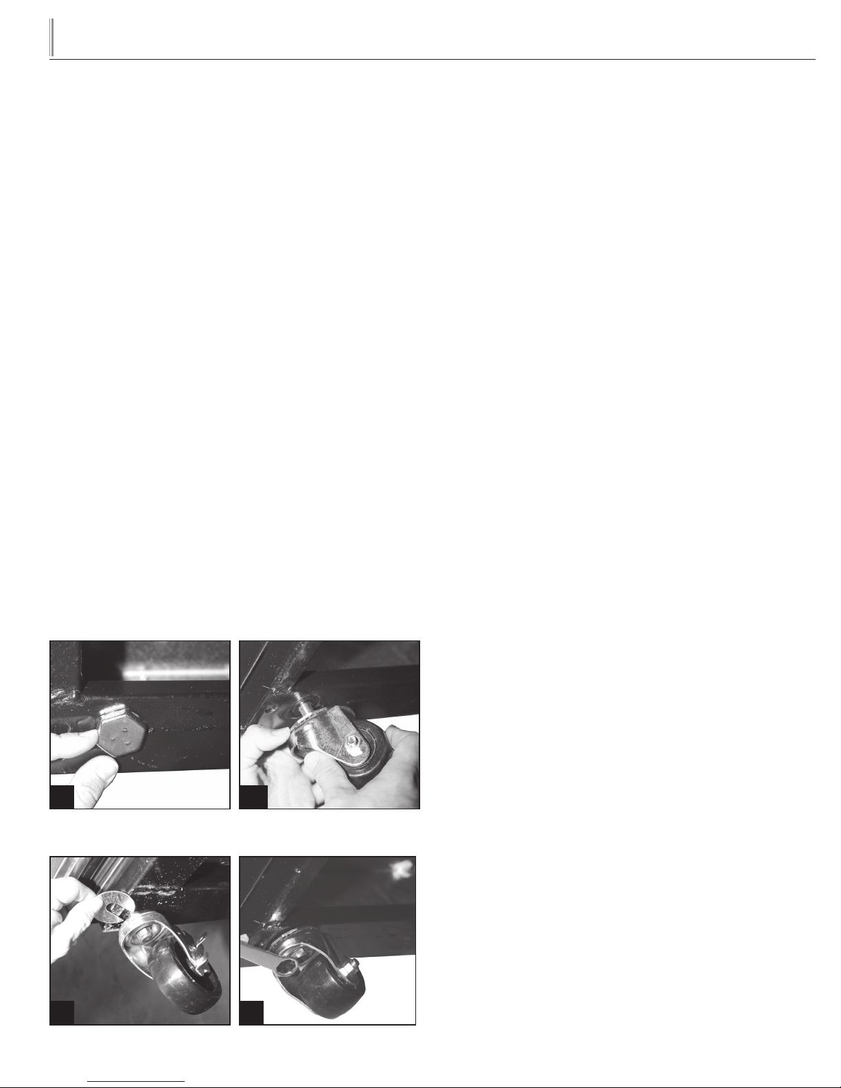
C. Move your display case as close to the final location as possible
before removing the wooden skid.
NOTE: KEYS FOR COOLERS WITH DOOR LOCKS
ARE LOCATED IN WARRANTY PACKETS.
INSTALLATION
ELECTRIC INSTALLATION & SAFETY
INFORMATION
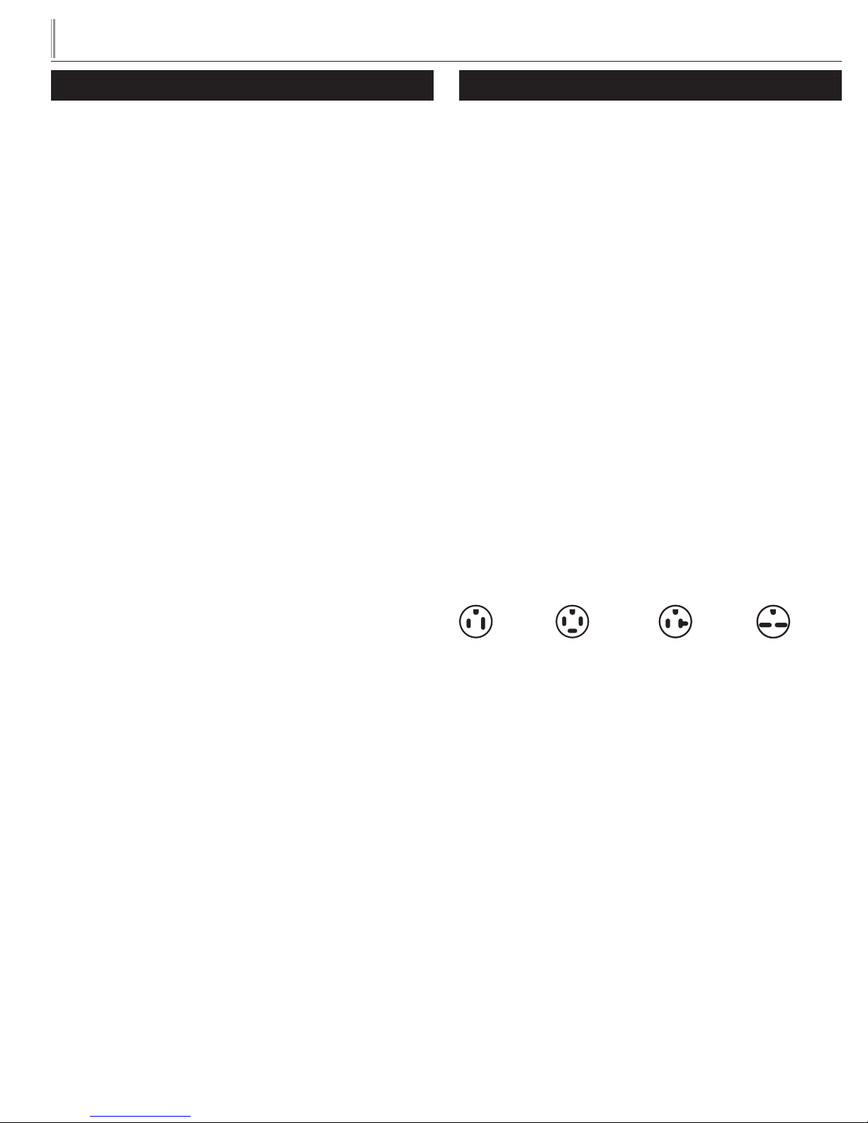
Hard wiring for a 30 amp circuit is required on specific Display Cases.'
Models standard with power cords: Do not, under any circumstances, cut
or remove the ground prong from the power cord. For personal safety, this
appliance must be properly grounded.
• If the supply cord is damaged, it must be replaced by a special
cord or assembly available from the manufacturer or its service
agent.
• Lamps must be replaced by identical lamps only.
• Appliance tested according to the climate classes 5 and 7
temperature and relative humidity.
ELECTRICAL INSTRUCTIONS
A. Before your new unit is connected to a power supply, check the
incoming voltage with a voltmeter. If anything less than 100% of
the rated voltage for operation is noted, correct immediately.
B. All units equipped with a service cord must be powered at
proper operating voltage at all times. Refer to cabinet data
plate for this voltage.
TRUE RECOMMENDS THAT A SOLE USE CIRCUIT BE
DEDICATED FOR THE UNIT.
WARNING: Compressor warranties are void if compressor burns
out due to low voltage.
WARNING: Power supply cord ground should not be removed!
WARNING: Do not use electrical appliances inside the food stor-
age compartments of the appliances unless they are of the type
recommended by the manufacturer.
NOTE: To reference wiring diagram, remove front louvered grill,
wiring diagram is positioned on the inside cabinet wall.
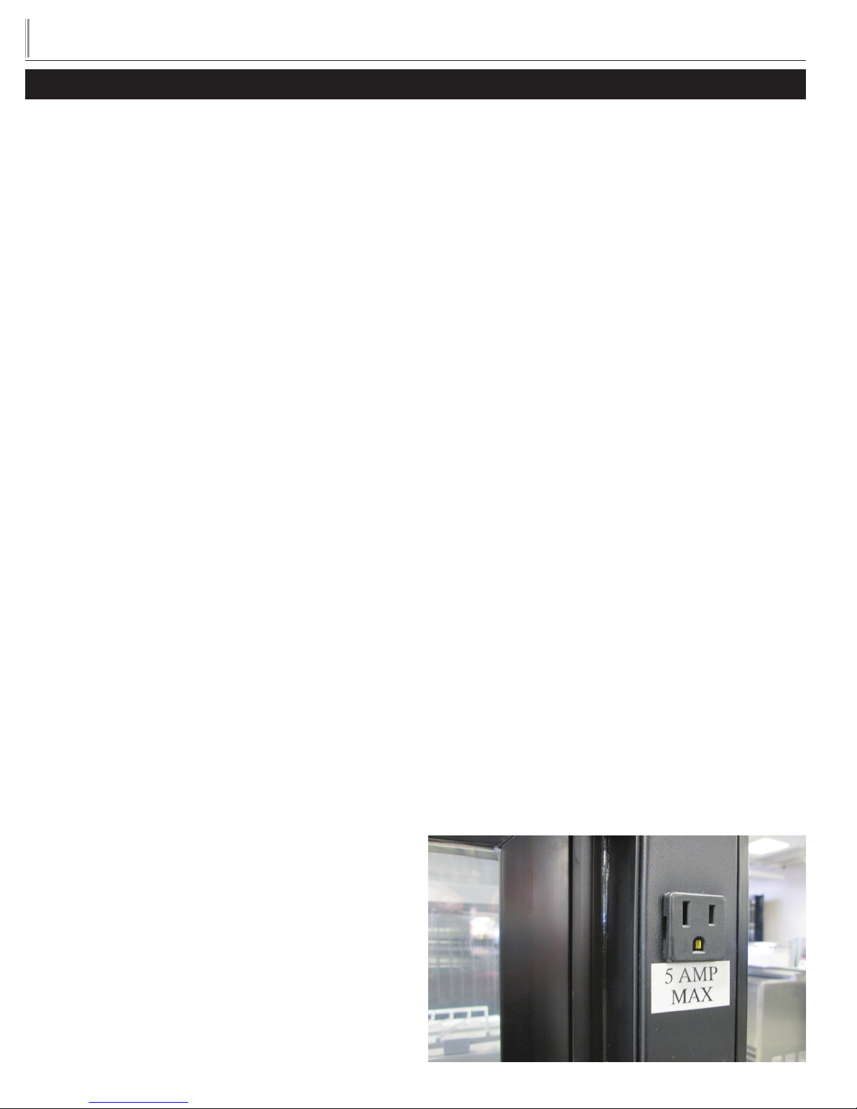
CURVED GLASS DISPLAY CASES
Some cases are equipped with a service receptacle, found on the
upper right cabinet and backside. No electrical load greater than 4-5
amps should be connected to this receptacle. Maximum Amp load is
listed on the label next to the service receptacle.
FOR REFERENCE ONLY