manuals.online logo
Brands
  1. Home
  2. •
  3. Brands
  4. •
  5. turck
  6. •
  7. Accessories
  8. •
  9. turck RU100-CP40 Series User manual

turck RU100-CP40 Series User manual

Umsetzen der aktiven Fläche ( C )
(Lieferzustand aktive Fläche vorne)
Changing of Sensing Face Position ( C )
(unit comes with sensing face in front)
Changement d´orientation de la face
active ( C ) (Appareil livré face active
frontale)
●Loosen screw ( B ) and remove
amplifier ( A ) with together sensor head
( D ) from the terminal socket ( F ).
●For "top" target approach loosen
screws ( E ), rotate sensor head ( D ) by
180° and re-tighten screws ( E ).
●For "bottom", "right" or "left" target
approach proceed as above ("top"
target approach). Remove sensor head
( D ) from the amplifier ( A ), rotate
sensor in 45° steps for the desired
target approach. Re-connect sensor
head ( D ) and amplifier ( A ).
●Insert amplifier ( A ) with sensor head
( D ) into the terminal socket ( F ) and
re-tighten screws ( B ).
●Desserrer les vis ( B ) et enlever la
partie électronique ( A ) avec la tête
de détection ( D ) du socle de
raccordement ( F ) .
●Lorsqu’on désire obtenir le sens
d’attaque "dessus“, desserrer les
vis ( E ), enlever la tête du détecteur ( D )
et la tourner de 180° et resserrer les
vis ( E ).
●Lorsqu’on désire obtenir le sens
d’attaque "dessous", "droite" ou
"gauche", regler le sens d’attaque
"dessus", séparer ensuite la tête de
détecteur ( D ) de la partie électronique
( A ), tourner par pas de 45° dans le
sens d’attaque souhaité et emboîter à
nouveau sur la partie électronique ( A ).
●Terminer en emboîtant la partie
électronique ( A ) avec la tête de
détection ( D ) sur le socle de
raccordement ( F ) et serrer les vis ( B ).
●Schrauben ( B ) lösen und Elekronikteil
( A ) zusammen mit Sensorkopf ( D )
vom Anschlusssockel ( F ) abziehen.
●Ist Anfahrrichtung "oben" gewünscht,
Schrauben ( E ) lösen, Sensorkopf ( D )
abheben und um 180° drehen,
Schrauben ( E ) wieder anziehen.
●Ist Anfahrrichtung "unten", "rechts" oder
"links" gewünscht, Anfahrrichtung "oben"
einstellen. Anschließend das Elektronik-
teil ( A ) vom Sensorkopf ( D ) abziehen,
den Sensorkopf in 45°-Schritten in die
gewünschte Anfahrrichtung drehen und
wieder aufs Elektronikteil ( A ) stecken.
●Abschließend Elektronikteil ( A ) mit
Sensorkopf ( D ) auf den Anschluss-
sockel ( F ) stecken und Schrauben ( B )
anziehen.
Détecteurs ultrasoniques
RU100-CP40…
Ultrasonic sensors
RU100-CP40…
Ultraschall-Sensoren
RU100-CP40…
(weitere Hinweise auf Rückseite) (further information overleaf) (informations supplémentaires au verso)
C
D
B
A
F
M20 x 1,5
60
30
ø 5,3
34
E
C
D
A
E
RU100-CP40…
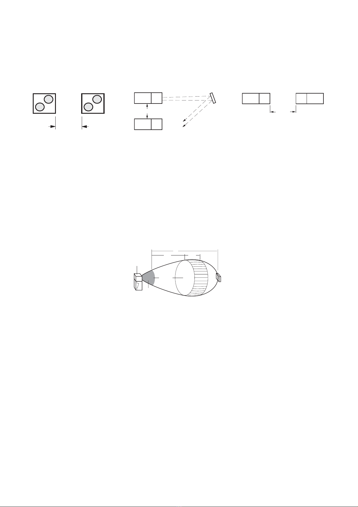
Einbauvorschriften bei Verwendung
mehrerer Sensoren
Bei ungünstiger Ausrichtung des Objektes
muss in Abhängigkeit des Winkels αein
größerer Abstand e gewählt werden. Stehen
sich zwei Sensoren gegenüber, muss der
Abstand f ≥ 6 m eingehalten werden.
Mounting instructions for multiple
sensors
If the object is unfavourably aligned, a larger
distance e must be selected according to the
angle α. If two sensors are opposite to each
other, a distance of f ≥6 m must be observed.
Prescriptions de montage lors de
l´utilisation de plusieurs détecteurs
Einstellhinweise
Der Schalt-/Messbereich B wird mit den
Potentiometern S1 und S2 eingestellt
(Werkseinstellung auf Minimum):
(1) Mit S1 innerhalb des Erfassungsbereichs A
(max. 180 cm) den Anfang des Bereichs B
(5...100 cm) einstellen.
(2) Mit S2 die Tiefe des Bereichs B
(10...100 cm)
En cas d’alignement défavorable de l’objet,
on doit choisir une distance plus grande en
fonction de l’angle α. Lorsque deux détec-
teurs se trouvent face à face respecter une
distance f ≥ 6 m.
Achtung: Betrieb in der Blindzone C unzulässig;
Mindestschaltabstand Smin = 5 cm beachten.
Adjustment guidelines
The switching/measuring range B is adjustable
by means of potentiometers S1 and S2
(factory setting: minimum range)
(1) Use S1 to set the beginning of measuring
range B (5...100 cm) within sensing range
A (max. 180 cm)
(2) Use S2 to set the depth of measuring
range B (10...100 cm)
Indications de réglage
La zone de commutation et de mesure B est
réglable à l’aide des potentiométres S1 et S2
(réglage minimum en usine)
(1) Ajuster le début de la zone B (5...100 cm)
à l’aide de S1 à l’intérieur de la zone de
détection A (max. 180 cm)
(2) Ajuster la profondeur de la zone B
(10...100 cm) à l’aide de S2
Attention: l’utilisation dans la zone morte C
n’est pas autorisée; respecter la distance
minimale Smin = 5 cm.
Ausgangswert des RU100-CP40-LIUX
Befindet sich das Betätigungselement vor oder
hinter dem Meßbereich B, ist der Ausgangswert
0 V (0 mA). Wird das Betätigungsobjekt inner-
halb des Messbereichs vom Sensor weg bewegt,
steigt der Ausgangswert von 0 V (0 mA) am
Messbereichsanfang linear bis zum Maximalwert
von 10 V (20 mA) am Meßbereichsende an.
LED-Anzeigefunktionen
RU100-CP40-AP6X2:
– gelbe LED leuchtet, wenn der Ausgang
durchgeschaltet ist
– grüne LED leuchtet, wenn ein Objekt
detektiert wird
RU100-CP40-LIUX:
– gelbe LED leuchtet stetig, wenn Betriebs-
spannung anliegt;
blinkt mit 20 Hz, wenn ein Objekt im
Messbereich B detektiert wird.
With the target in front or behind measuring
range B the output value is 0 V (0 mA). When
the target is moved away from the sensor
within the measuring range, the output value
increases linearly from 0 V ( 0 mA) at the lower
end of the measuring range up to the maxi-
mum value of 10 V (20 mA) at the upper end.
LED indications
RU100-CP40-AP6X2:
– yellow LED on, if output is activated
– green LED on, if an object is detected
RU100-CP40-LIUX:
– yellow LED constantly on, if power is
applied;
flashes with 20 Hz, if an object is
detected in measuring range B.
La valeur de sortie est de 0 V (0 mA) lorsque
l’élément de commande se trouve devant ou der-
rière la zone de mesure B. Lorsque l’élément de
commande est éloigné du détecteur à l’intérieur
de la zone de mesure, la valeur de sortie aug-
mente de façon linéaire de 0 V (0 mA) au début
de la plage de mesure jusqu’à la valeur maximale
de 10 V (20 mA) à la fin de la plage de mesure.
Fonction des LED de signalisation
RU100-CP40-AP6X2:
– LED jaune allumée,
lorsque la sortie est commutée
– LED verte allumée,
lorsqu’un objet est détecté
RU100-CP40-LIUX:
– LED jaune allumée de façon continue,
lorsque la tension de service est présente;
clignote avec une fréquence de 20 Hz,
lorsqu’un objet est détecté dans la zone
de mesure B.
A
CB
S1 S2
60°
Sensor
Attention: It is not permitted to use the
sensor in blind zone C; observe the minimum
switching distance Smin = 5 cm.
Output value of RU100-CP40-LIUX Valeur de sortie du RU100-CP40-LIUX
D101086 0103 *D101086ßß0103*
Irrtümer und Änderungen vorbehalten / Subject to change without notice / Sous réserve de modifications • © Hans Turck GmbH & Co. KG 2003
Hans Turck GmbH & Co. KG • D–45466 Mülheim/Ruhr • Tel. 0208/4952-0 • Fax 0208/4952-264 • E-Mail: [email protected] • www.turck.com
e ³ 1m
e
a
f ³ 6 m

Other turck Accessories manuals

turck RU D UPN8X2 Series User manual

turck

turck RU D UPN8X2 Series User manual

turck FCS-G1/2HC22-NAEX/D100 5M User manual

turck

turck FCS-G1/2HC22-NAEX/D100 5M User manual

turck BI2-M12-Y1X-H1141 User manual

turck

turck BI2-M12-Y1X-H1141 User manual

turck PK01VR N Series User manual

turck

turck PK01VR N Series User manual

turck Li-Q25LxE Series User manual

turck

turck Li-Q25LxE Series User manual

turck BI1.5-HS865-Y1 User manual

turck

turck BI1.5-HS865-Y1 User manual

turck uprox BI6U-M12 Series User manual

turck

turck uprox BI6U-M12 Series User manual

turck NI4-DSU35-2Y1X2-H1140 User manual

turck

turck NI4-DSU35-2Y1X2-H1140 User manual

turck uprox + BI4U-EM12WD-AP6X-H1141/3GD User manual

turck

turck uprox + BI4U-EM12WD-AP6X-H1141/3GD User manual

turck LPRE-M30-AP6X2-H1141 User manual

turck

turck LPRE-M30-AP6X2-H1141 User manual

turck FCS-G1/2A4-NAEX0-H1141/L065 User manual

turck

turck FCS-G1/2A4-NAEX0-H1141/L065 User manual

turck FCS-DN NAEX0 Series User manual

turck

turck FCS-DN NAEX0 Series User manual

turck FCS-GL1/2TN-NAEX-H1141 User manual

turck

turck FCS-GL1/2TN-NAEX-H1141 User manual

turck PK01VR P Series Instruction manual

turck

turck PK01VR P Series Instruction manual

turck PS Series User manual

turck

turck PS Series User manual

turck RU600 Series User manual

turck

turck RU600 Series User manual

turck FCS-GL1/2A4-NAEX/D100 User manual

turck

turck FCS-GL1/2A4-NAEX/D100 User manual

turck BC3-M12-AP6X 15M User manual

turck

turck BC3-M12-AP6X 15M User manual

turck S120 User manual

turck

turck S120 User manual

turck FCS-G1/2A4-NAEX0/L065/D024 User manual

turck

turck FCS-G1/2A4-NAEX0/L065/D024 User manual

turck NI4-DSU35TC-2AP4X2/3GD User manual

turck

turck NI4-DSU35TC-2AP4X2/3GD User manual

turck FCS-G1/4A4-NAEX User manual

turck

turck FCS-G1/4A4-NAEX User manual

turck FCS-G1/2A4-NAEX0/L065 User manual

turck

turck FCS-G1/2A4-NAEX0/L065 User manual

turck FCS-G3/4A4-NAEX/D100 User manual

turck

turck FCS-G3/4A4-NAEX/D100 User manual

Popular Accessories manuals by other brands

Quincy lab 140AE-1 operating manual

Quincy lab

Quincy lab 140AE-1 operating manual

HomePro ZIR000 user manual

HomePro

HomePro ZIR000 user manual

DOL 20SCR Technical user guide

DOL

DOL 20SCR Technical user guide

RAB Smart Task installation manual

RAB

RAB Smart Task installation manual

Kemppi KMS 300 quick guide

Kemppi

Kemppi KMS 300 quick guide

Stearns 57,500 Series Installation and service instructions

Stearns

Stearns 57,500 Series Installation and service instructions

iGuzzini TWILIGHT COPENAGHEN manual

iGuzzini

iGuzzini TWILIGHT COPENAGHEN manual

Adelaide Annexe & Canvas Avan Deluxe installation guide

Adelaide Annexe & Canvas

Adelaide Annexe & Canvas Avan Deluxe installation guide

OHAUS 5000 instruction manual

OHAUS

OHAUS 5000 instruction manual

HOME8 WLS1300 quick start guide

HOME8

HOME8 WLS1300 quick start guide

MAXBOTIX MaxSonar quick start guide

MAXBOTIX

MAXBOTIX MaxSonar quick start guide

ioSmart iSmart56 Installation and user guide

ioSmart

ioSmart iSmart56 Installation and user guide

Focusrite Scarlett 18i8 user guide

Focusrite

Focusrite Scarlett 18i8 user guide

Velleman ED38105 user manual

Velleman

Velleman ED38105 user manual

JumpSport SkyBounce user manual

JumpSport

JumpSport SkyBounce user manual

Prima-Temp PRIYA Instructions for use

Prima-Temp

Prima-Temp PRIYA Instructions for use

Tefcold BC85I-BC85I W user manual

Tefcold

Tefcold BC85I-BC85I W user manual

Vaisala WMS302 user guide

Vaisala

Vaisala WMS302 user guide

manuals.online logo
manuals.online logoBrands
  • About & Mission
  • Contact us
  • Privacy Policy
  • Terms and Conditions

Copyright 2025 Manuals.Online. All Rights Reserved.