manuals.online logo
Brands
  1. Home
  2. •
  3. Brands
  4. •
  5. turck
  6. •
  7. Measuring Instrument
  8. •
  9. turck FTCI-3/4D15A4P-2LUX-H1141 User manual

turck FTCI-3/4D15A4P-2LUX-H1141 User manual

EN Quick-Start Guide
FTCI-3/4D15A4P-2LUX-H1141
Other documents
Besides this document, the following material can be found on the Internet
at www.turck.com:
■Data sheet
■EU declaration of conformity (current version)
For your safety
Intended use
The devices are designed only for use in industrial areas.
The devices are used for flow measurement of water/glycol mixes up to
70%, deionized water, HT110 and HT135.
The devices can monitor the flow rate and temperature and display these
values on a three-digit seven-segment display. The devices are intended for
inline mounting in a pipe.
The devices must only be used as described in these instructions. Any other
use is not in accordance with the intended use. Turck accepts no liability for
any resulting damage.
Obvious misuse
The devices are not safety components and must not be used for personal or
property protection.
General safety notes
■The device must be mounted, installed, operated, parameterized and
maintained only by trained and qualified personnel.
■The monitored medium must be free of air pockets and bubbles.
Product description
Device overview
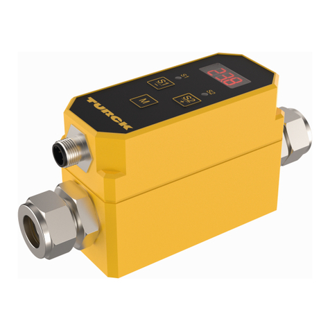
See Fig. 1 (product image)
Functions and operating modes
The devices have two analog outputs (0…10V). A voltage signal for the flow
rate is issued at output 1, while a voltage signal for the temperature value
is issued at output 2. The values for flow rate and temperature can also be
shown alternately on the display. The following device functions can be
configured using the three buttons on the front of the device:
■Access code: protects the device from unauthorized programming access
■Initial temperature value/final temperature value
■Mean value generation: sets a time interval for generating the mean value
of the measuring signal (2…16s). A low value results in a fast response, a
higher value results in the steady display of the measured value.
■Media selection: sets the media to be monitored.
■Reference function: changes the value shown in the display by ± 25%.
Mounting
CAUTION
Shearing forces between the pipe connections of the device
Damage to equipment caused by shearing forces
➤Mount the device in such a way that shearing forces between the pipe
connections of the device are prevented. See Fig. 2
The devices are intended for inline mounting in a pipe. When installing, the
pipe can be connected either directly via the cutting ring fitting or by using
an adapter (not included in the delivery).
➤ Pay attention to the flow direction when mounting (see type label).
Mounting the cutting ring tting
➤ If mounting the device without using an adapter, use a precision pipe
(3/4”) in accordance with DIN2391.
➤ Cut the pipe to length with a perpendicular cut and remove burrs.
➤ Slide the union nut onto the pipe, along with the clamp ring and cutting
ring.
➤ Insert the pipe in the fitting body as far as it will go.
➤ Tighten the union nut by hand and check the position of the pipe.
➤ Apply an AF27 wrench to the sensor connection.
➤ Tighten the union nut by 1 ¼ turns.
➤ Check that the pipe is securely seated.
Mounting the housing
The sensor is equipped with four M4 threaded bushes with a depth of 5mm
in the bottom of the housing to facilitate mounting.
➤ Mount the device at the intended location using four M4 screws.
Alternatively:
➤ Mount the device on mounting plate FTCI-MP01AL (Ident-No. 6870040,
not included in the delivery). With the mounting plate, it is possible to
install the device from the front.
Connection
➤ Connect the device in accordance with the “Wiring Diagram.”
Commissioning
The device is operational automatically once the power supply is switched
on.
© Hans Turck GmbH & Co. KG | 100017718 2020-03 EN
FTCI-3/4D15A4P-2LUX-H1141
FTCI-3/4D15A4P-2LUX-H1141
Flow Meter
Quick-Start Guide
Doc.-No. 100017718 2003
Additional
information see
turck.com

Wiring Diagram
–
+
2 WH
4 BK
1 BN
3 BU
U
TEMP
U
FLOW
FC
➤ Exit programming mode: Press and hold the [M] button for at least 3s
until the display stops flashing.
Changing the temperature unit
➤ Disconnect the sensor from the supply voltage.
➤ Reconnect the sensor while pressing the [V/-] and [V/+] buttons
➥ [°F] or [°C] appears on the display.
➤ Change the temperature unit using the [V/+] button.
➤ Confirm the selection using the [M] button.
➥ The programmed values for t0 and t10 will be set to 0 °C/32 °F for 0 V and
80 °C or 176 °F for 10 V after changing the temperature unit.
Changing the ow unit
➤ Disconnect the sensor from the supply voltage.
➤ Reconnect the sensor while pressing the [V/-] and [V/+] buttons
➤ Enter the access code.
➥ [GAL] or [L] appears on the display.
➤ Select the flow unit using the [V/+] button.
➤ Confirm the selection using the [M] button.
Resetting the device to the factory settings (see “Factory settings”)
➤ Disconnect the sensor from the supply voltage.
➤ Reconnect the sensor while pressing the [M] button.
➥ [rES] appears on the display.
➤ Enter the access code.
➤ To reset the device, press the [M] button.
Maintenance
Operating the device in contaminated or chalky water causes deposits that
can distort measurements.
➤ Clean the part of the sensor through which the medium flows. During
cleaning, ensure that the metallic surface of the sensor is not damaged.
Repair
The device must not be repaired by the user. The device must be decom-
missioned if it is faulty. Observe our return acceptance conditions when
returning the device to Turck.
Disposal
The devices must be disposed of correctly and must not be included
in normal household garbage.
EN Quick-Start Guide
Operation
The device has three buttons on the front that can be used to activate func-
tions and configure settings. All values are shown in the display.
Button Function in normal mode
Function in programming mode
V/- Displays the current value for
the flow rate in V
Reduces the displayed value
V/+ Displays the current value for
the temperature in V
Increases the displayed value
M Displays the currently measured
temperature or the current flow
rate for 3s
Selects functions and
parameters
Changing the displayed value
➤ Press the [M] button as per the table below:
Press [M] Displayed function Possible display values
1x Current temperature -10…+90
2x Initial temperature value 0V (t0) 14…162°F/-9.9…+74.0°C
3x
Final temperature value 10V (t10)
46…194°F/6.1…90.0°C
4x Time interval for mean value
generation (nfi)
2…16
5x Fluid (FLU) GLY, di, 110, 135
➥ The selected value is shown on the display for approximately 3s.
Setting
➤ Start programming mode: Press and hold the [V/-] and [V/+] buttons at
the same time for at least 3s until the display starts to flash.
➤ Enter the access code (factory setting: 0).
➤ Select the value to be set: Press the [M] button as per the table below:
Press [M] Congurable function Possible display values
1x Enter the access code (Cod) 0…255
2x Initial temperature value 0V in
°F (t0)
14…162°F
3x Final temperature value 10V in
°F (t10)
46…194°F
4x Time interval for mean value
generation (nfi)
2…16
5x Fluid (FLU) GLY: glycol 0…70 %
di: deionized water
110: HT110
135: HT135
6x Reference function ± 25% (CAL)
7x Configure the display: tempera-
ture only, flow rate only, flow
rate and temperature alter-
nately (diS)
°F…GAL…°FG
8x Change the access code (COD) 0…255
Hans Turck GmbH & Co. KG | Witzlebenstraße 7, 45472 Mülheim an der Ruhr, Germany | Tel. +49 208 4952-0 | Fax +49 208 4952-264 | [email protected] | www.turck.com © Hans Turck GmbH & Co. KG | 100017718 2020-03 EN
FTCI-3/4D15A4P-2LUX-H1141
Technical Data
Technical data FTCI-3/4D15A4P-2LUX-H1141
Ident-No. 6878041
Supply voltage 24 V DC ± 10% (PIN1: BN +, PIN3: BU -)
Current consumption 100 mA
Ambient temperature 32…140 °F
Output 1 Flow – analog 0…10 V (PIN 4: BK)
Output 2 Temperature – analog 0…10 V (PIN 2: WH)
Load 50…500 Ω
Medium temperature 14…194 °F
Detection range flow
Water
Water/monoethylenglycol 0…70 %
1…12 gpm
1…12 gpm
Display range 0.8…14.4 gpm
Detection range temperature 14…194 °F
Accuracy temperature ± 5 °F (68…158 °F: ± 3.0 °F) (Flow rate >
3 gpm)
Adjustment range temperature 4 mA: 14…162 °F
20 mA: 46…194 °F
t20 mA – t4 mA ≥ 32 °F
Reaction time 2…8 s
Material sensor AISI 316 Ti / FKM
Material housing PBT
Protection IP 65
Compressive strength 20 bar
Factory setting code 0
Factory Settings
Unit flow gpm
Unit temperature °F
t0 32 °F
t10 176 °F
nFi 8
Medium Water
Display Flow only (gal)
This manual suits for next models

1

Other turck Measuring Instrument manuals

turck IM34-11Ex-i User manual

turck

turck IM34-11Ex-i User manual

turck FMX-IM-2UPLI63X User manual

turck

turck FMX-IM-2UPLI63X User manual

turck B2N45H-Q20L60-2Li2-H1151/3GD User manual

turck

turck B2N45H-Q20L60-2Li2-H1151/3GD User manual

turck IM21-14Ex-CDTRi User manual

turck

turck IM21-14Ex-CDTRi User manual

turck duotec Latooyete User manual

turck

turck duotec Latooyete User manual

turck IMXK12-AO01 Series User manual

turck

turck IMXK12-AO01 Series User manual

turck B1N360V-QR20-IOLX3 Series User manual

turck

turck B1N360V-QR20-IOLX3 Series User manual

turck IM18-CCM Series User manual

turck

turck IM18-CCM Series User manual

turck IM21-14Ex-CDTRi User manual

turck

turck IM21-14Ex-CDTRi User manual

turck FCI-X-H114 Series User manual

turck

turck FCI-X-H114 Series User manual

turck B1N360V-Q20L60-2UP6X3-H1151/3GD User manual

turck

turck B1N360V-Q20L60-2UP6X3-H1151/3GD User manual

turck B1N360V-Q20L60-2Li2-H1151/3GD User manual

turck

turck B1N360V-Q20L60-2Li2-H1151/3GD User manual

turck IMX12-CCM02 Series User manual

turck

turck IMX12-CCM02 Series User manual

turck BL ident TW-R30-B128-EX User manual

turck

turck BL ident TW-R30-B128-EX User manual

turck IM18-CCM51-12I User manual

turck

turck IM18-CCM51-12I User manual

turck B N QR20-2UPN Series User manual

turck

turck B N QR20-2UPN Series User manual

turck B N Series User manual

turck

turck B N Series User manual

turck B N -QR20-IOL Series User manual

turck

turck B N -QR20-IOL Series User manual

turck IM18-CCM40 User manual

turck

turck IM18-CCM40 User manual

turck MK21-122Ex0-R User manual

turck

turck MK21-122Ex0-R User manual

turck IM18-CCM40 User manual

turck

turck IM18-CCM40 User manual

turck LMA-4 User manual

turck

turck LMA-4 User manual

turck FCMI Series User manual

turck

turck FCMI Series User manual

turck FM-FX/FMX-FX Series User manual

turck

turck FM-FX/FMX-FX Series User manual

Popular Measuring Instrument manuals by other brands

Pittsburgh 63656 owner's manual

Pittsburgh

Pittsburgh 63656 owner's manual

Gecko Compact Product user manual

Gecko

Gecko Compact Product user manual

horiba LAQUA WQ-300 Series quick guide

horiba

horiba LAQUA WQ-300 Series quick guide

Metrohm NIRS manual

Metrohm

Metrohm NIRS manual

Thyracont VD8 Series operating instructions

Thyracont

Thyracont VD8 Series operating instructions

PCE Instruments PCE-MMK 1 user manual

PCE Instruments

PCE Instruments PCE-MMK 1 user manual

Ele 29-3729 operating instructions

Ele

Ele 29-3729 operating instructions

MG R7MWTU instruction manual

MG

MG R7MWTU instruction manual

Extech Instruments 401027 user manual

Extech Instruments

Extech Instruments 401027 user manual

Kanomax OMX-SRM Operation manual

Kanomax

Kanomax OMX-SRM Operation manual

Elditest CT4025 user manual

Elditest

Elditest CT4025 user manual

Biolase epic V series user manual

Biolase

Biolase epic V series user manual

Siemens Sitrans F Series operating instructions

Siemens

Siemens Sitrans F Series operating instructions

BRUEL & KJAER 2221 instruction manual

BRUEL & KJAER

BRUEL & KJAER 2221 instruction manual

Minolta MULTI GLOSS 268 brochure

Minolta

Minolta MULTI GLOSS 268 brochure

BTI MoTeC M130 manual

BTI

BTI MoTeC M130 manual

Keeler IntelliPuff Service manual

Keeler

Keeler IntelliPuff Service manual

Foxwell BT705 user guide

Foxwell

Foxwell BT705 user guide

manuals.online logo
manuals.online logoBrands
  • About & Mission
  • Contact us
  • Privacy Policy
  • Terms and Conditions

Copyright 2025 Manuals.Online. All Rights Reserved.