1.1 Input Voltage Range
¡Input voltage range of the power supplies is from AC85V to
AC264V (please see SPECIFICATIONS for details).
¡To comply with safety standards, input voltage range is AC100-
AC240V(50/60Hz).
¡If input value doesn’t fall within above range, a unit may not oper-
ate in accordance with specifications and/or start hunting or fail.
If you need to apply a square waveform input voltage, which is
commonly used in UPS and inverters, please contact us.
¡When the input voltage changes suddenly, the output voltage
might exceed the specification. Please contact us.
¡When DC input voltage is applied, external DC fuse is required for
the protection. Please contact us about detail.
¿ PLA100F, PLA150F
¡Power factor correction circuit will be stopped at AC250Vin
or more. The operation is normal except decreasing the power
factor. Please contact us about detail.
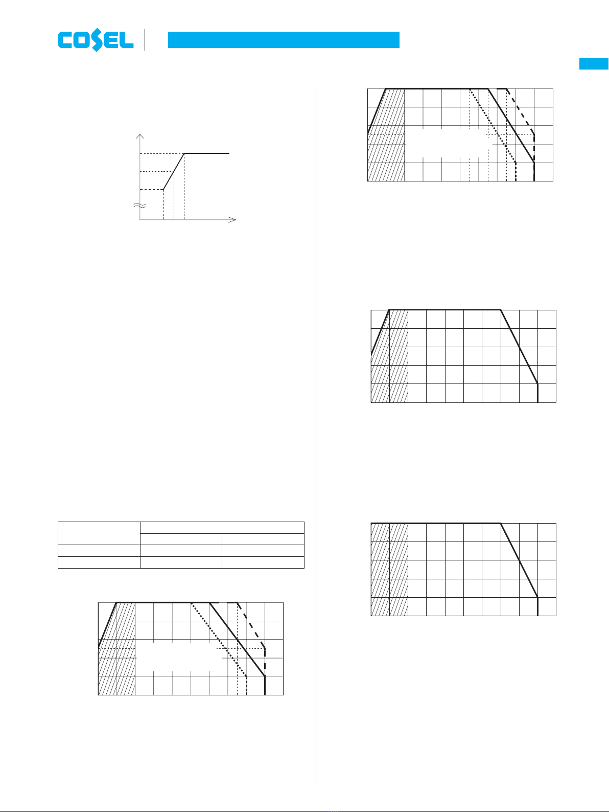
¡Operation stop voltage is set at a lower value by output power de-
rating.
-Use Conditions Maximum output power
PLA100F 40W
PLA150F 60W
Input AC50V (DC70V)
Duty 1s/30s
*Please avoid using continuously for more than 1 second
under above conditions. Doing so may cause a failure.
¿ PLA300F, PLA600F
¡By using -U option, it is possible to operate at input voltage dip
condition that is lower than AC85V. Output derating is required
(Refer to 5. Option and Others). Please contact us for details.
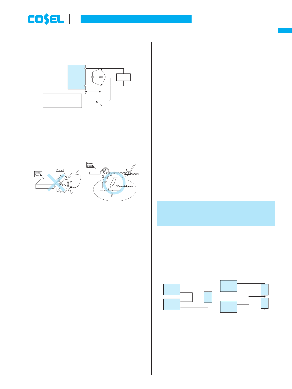
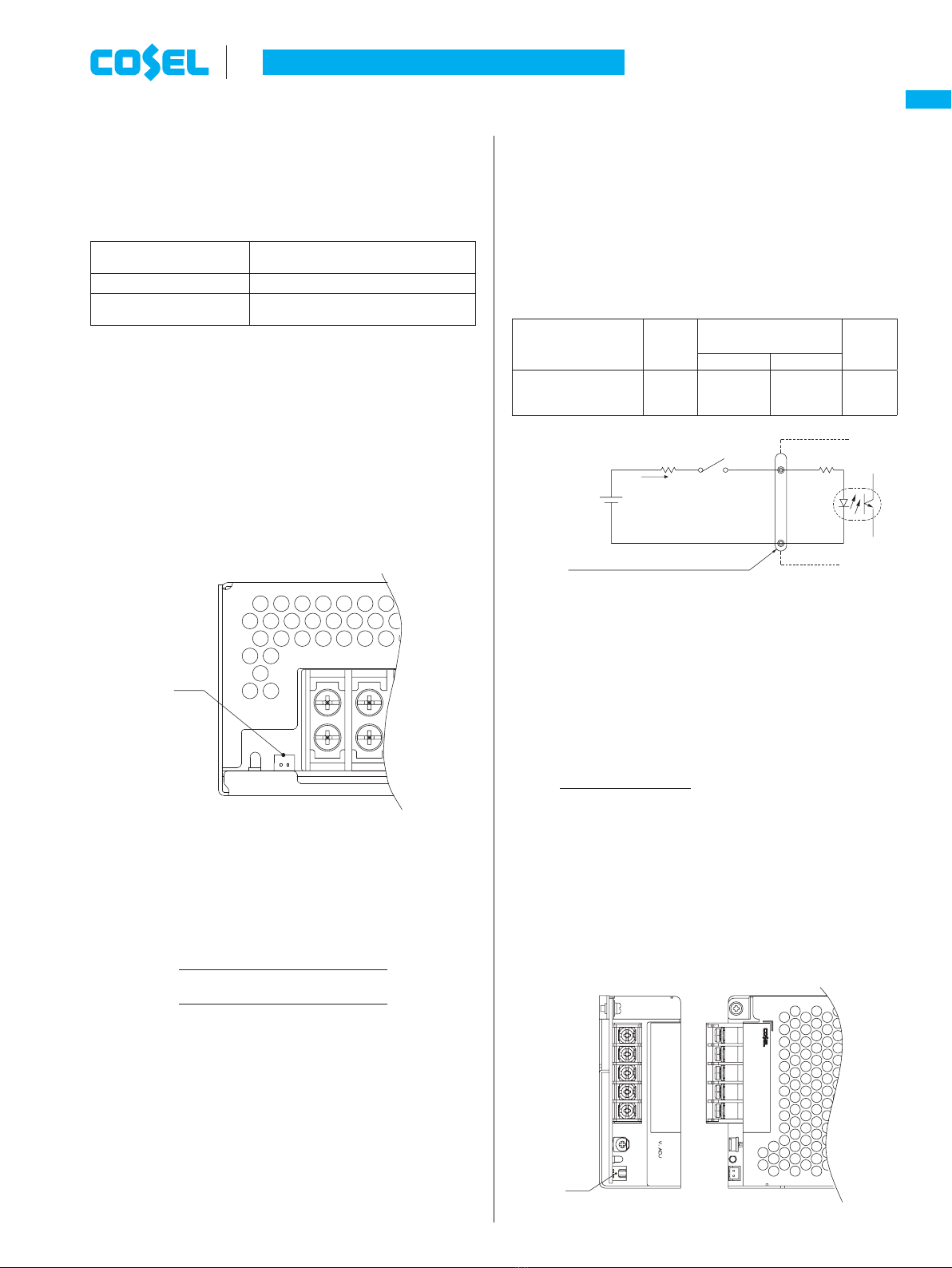
1.2 Inrush Current Limiting
¡An inrush current limiting circuit is built-in.
¡If you need to use a switch on the input side, please select one
that can withstand an input inrush current.
¿ PLA100F, PLA150F, PLA300F
¡Thermistor is used in the inrush current limiting circuit. When you
turn the power ON/OFF repeatedly within a short period of time,
please have enough intervals so that a power supply cools down
before being turned on.
¿ PLA600F
¡Thyristor technique is used in the inrush current limiting circuit.
When you turn the power ON/OFF repeatedly within a short period
of time, please have enough intervals so that the inrush current
limiting circuit becomes operative.
1 Function ¡When the switch of the input is turned on, the primary inrush cur-
rent and secondary inrush current will be generated because the
thyristor technique is used for the inrush current limiting circuit.
1.3 Overcurrent Protection
¡An overcurrent protection circuit is built-in and activated at 105%
of the rated current. An unit automatically recovers when a fault
condition is removed.
Please do not use a unit in short circuit and/or under an overcur-
rent condition.
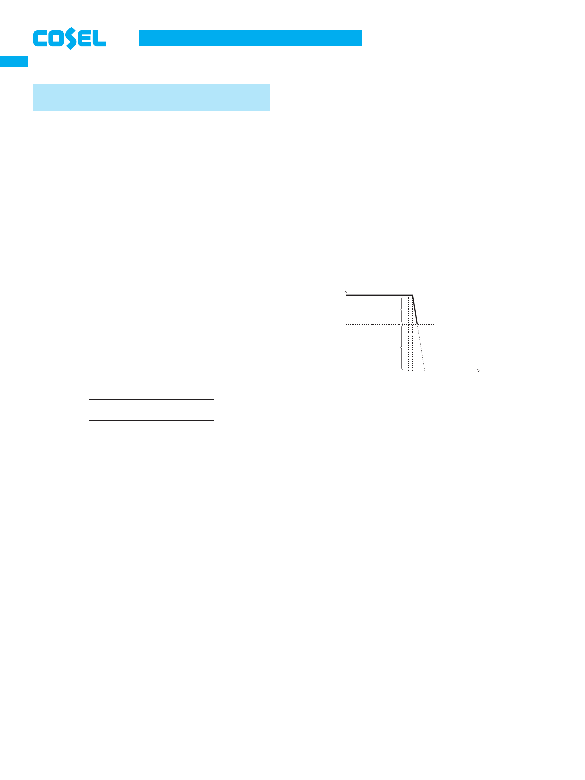
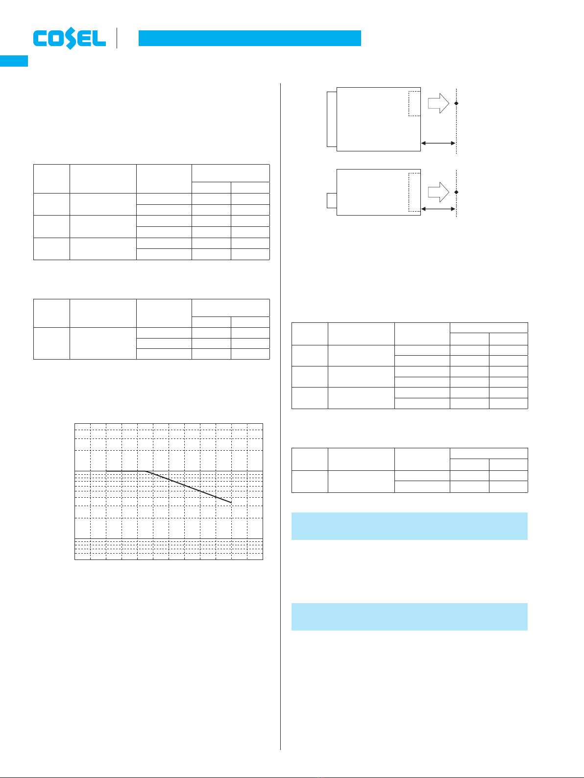
¡Intermittent Operation Mode
When the overcurrent protection circuit is activated and the output
voltage drops to a certain extent, the output becomes intermittent
so that the average current will also decrease.
¡When used with overcurrent at start-up, power supply may not
start-up by Intermittent operation mode. See the characteristics
below. (PLA100F, PLA150F)
100%
0%
Vo
Intermittent operation
start voltage
Not Intermittent
operation
Intermittent
operation
100 105min Io
Load factor [%]
Fig.1.1 Overcurrent protection characteristics
1.4 Overvoltage Protection
¡An overvoltage protection circuit is built-in. If the overvoltage pro-
tection circuit is activated, shut down the input voltage, wait more
than 3 minutes and turn on the AC input again to recover the out-
put voltage. Recovery time varies depending on such factors as
input voltage value at the time of the operation.
Remarks :
Please avoid applying a voltage exceeding the rated voltage to an
output terminal. Doing so may cause a power supply to malfunc-
tion or fail. If you cannot avoid doing so, for example, if you need
to operate a motor, etc., please contact us for details.
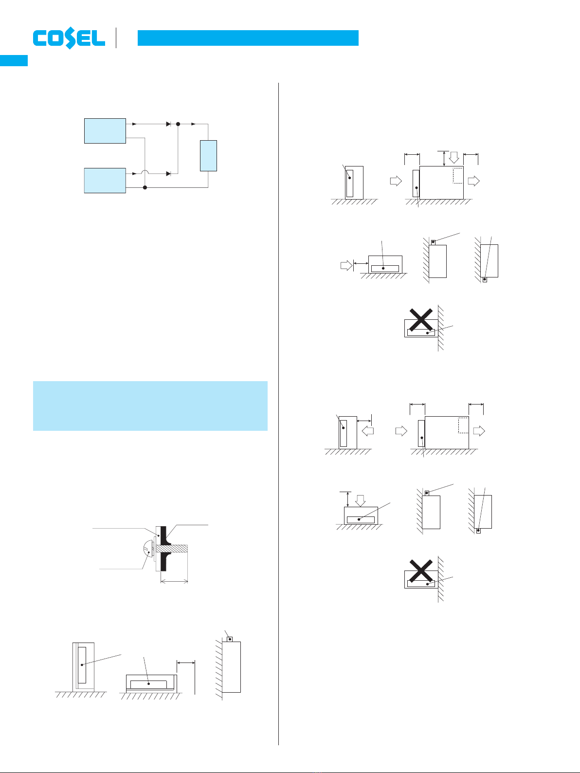
1.5 Thermal Protection
¿ PLA100F, PLA150F
¡PLA100F and PLA150F do not have thermal protection.
¿ PLA300F, PLA600F
¡A thermal protection circuit is built-in.
The thermal protection circuit may be activated under the follow-
ing conditions and shut down the output.
1
When a current and a temperature continue to exceed the val-
ues determined by the derating curve.
2
When a fan stops or air flow is blocked from the fan and weak-
ens.
If the thermal protection circuit is activated, shut off the input volt-
age and eliminate all the overheating conditions. To recover the
output voltage, have enough time to cool down the unit before
turning on the input voltage again.
AC-DC Power Supplies Enclosed type Instruction Manual
PLA-12
PLA
mepla1.inddPLA-12me pla1 indd PLA-12 2014/03/0410:34:422014/03/04 10:34:42