Turnstiles OST Instruction Manual

OST FULL HEIGHT SINGLE TURNSTILE
INSTALLATION & USER’S MANUAL

Orion reserves the right to make changes in this document without prior notice.
WARNING!
Safety instructions
READ CAREFULLY!
BEFORE INSTALLING AND STARTING UP THE DEVICE, PLEASE OBSERVE THE
SAFETY INSTRUCTIONS LISTED IN THE FOLLOWING SECTIONS. THIS WILL
HELP YOU TO AVOID MAKING SERIOUS ERRORS THAT COULD IMPAIR YOUR
HEALTH, DAMAGE THE DEVICE AND ENDANGER OTHERS. WE THEREFO-RE
RECOMMEND THAT YOU KEEP THIS MANUAL IN CLOSE PROXIMITY TO THE
INSTALLATION.
THE SAFETY OF THIS DEVICE AND ITS PROPER FITTING DEPENDS,
THEREFORE, ON RESPECTING ITS TECHNICAL CHARACTERISTICS AND
PROPER FITTING, TO BE DONE PROPERLY, AND UNDER SAFE CONDITIONS AS
EXPLAINED IN THE TECHNICAL DOCUMENT THAT COMES WITH THE DEVICE.
THIS DEVICE SHOULD ONLY BE USED FOR THE PURPOSE FOR WHICH IT WAS
EXPLICITLY DESIGNED. ANY OTHER USE IS DANGEROUS. TANSA IS NOT
LIABLE FOR ANY DAMAGE CAUSED BY IMPROPER, WRONGFUL AND
UNREASONABLE USE
STORAGE RECOMMENDATIONS
•THE RECOMMENDED MAXIMUM STORAGE TIME IS 6 MONTHS. IT SHOULD
BE NOTED THAT EQUIPMENT STORED FOR A LONGER PERIOD THAN THE
MAXIMUM STORAGE TIME INDICATED MUST BE INSPECTED BEFORE USED.
•THE UNITS MUST NOT BE STACKED AND SHOULD BE STORED OFF THE
GROUND, UNDER COVER PROTECTED FROM WEATHER, CONSTRUCTION
ACTIVITIES AND EXTREME TEMPERATURES
•BE CAREFUL WHEN HANDLING DEVICES THAT WEIGH OVER 25 KG. IF
NEEDED, USE PROPER SAFETY HOISTING EQUIPMENT.
•MINIMUM TWO PEOPLE MUST ALWAYS BE USED TO MOVE EACH
PEDESTAL, DUE TO ITS WEIGHT AND SIZE. ALWAYS PLAN THE PATH AND
ALLOCATE WHERE THE PEDESTAL WILL BE MOVED TO. THIS IS THE ONLY
WAY TO AVOID ACCI DENTS AND DAMAGE TO THE EQUIPMENT.
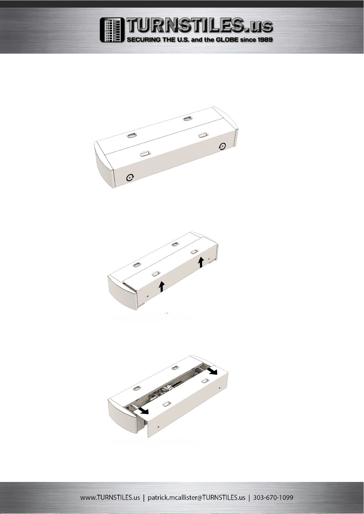
BEFORE INSATALLING
•(CHECK, IF SOMETHING IS MISSING, DO NOT CONTINUE UNTIL YOU HAVE
COMPLIED WITH ALL SAFETY PROVISIONS)
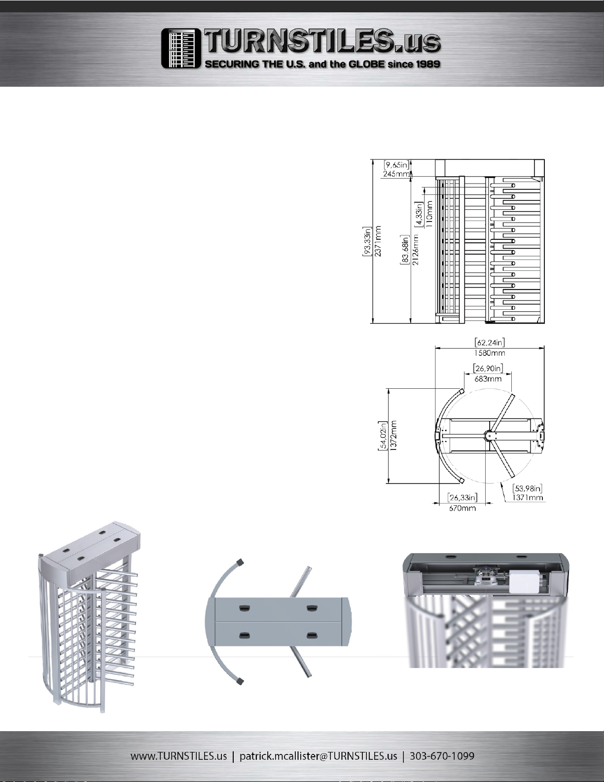
•IT IS ESSENTIAL THAT THE INFORMATION ON INSTALLATION AND THE
TECHNICAL DATA FOR THE DEVICE BE OBSERVED DURING UNPACKING AND
INSTALLATION AND BEFORE OPERATING THE DEVICE. THIS INCLUDES
DIMENSIONS, ELECTRI CAL VALUES, NECESSARY AMBIENT AND CLIMATIC
CONDITIONS, ETC.
•FITTING AND TESTING MUST BE BE ONLY PERFORMED BY QUALIFIED
TECHNICIANS.
•LAYING THE CABLES, INSTALLATION AND TESTING MUST FOLLOW PROPER
PROCEDURES AS DICTATED BY LOCAL REGULATIONS.
•MAKE SURE THE DEVICE IS IN GOOD MECHANICAL STATE, BALANCED
AND ALIGNED, AND THAT IT OPENS AND CLOSES PROPERLY. ALSO, IF
NEEDED, FIT SUITABLE PROTECTIONS OR USE PROPER SAFETY SENSORS.
•MAKE SURE THAT THE OPENING TURNSTILE CAN NOT RESULT IN ANY
HAZARDS.
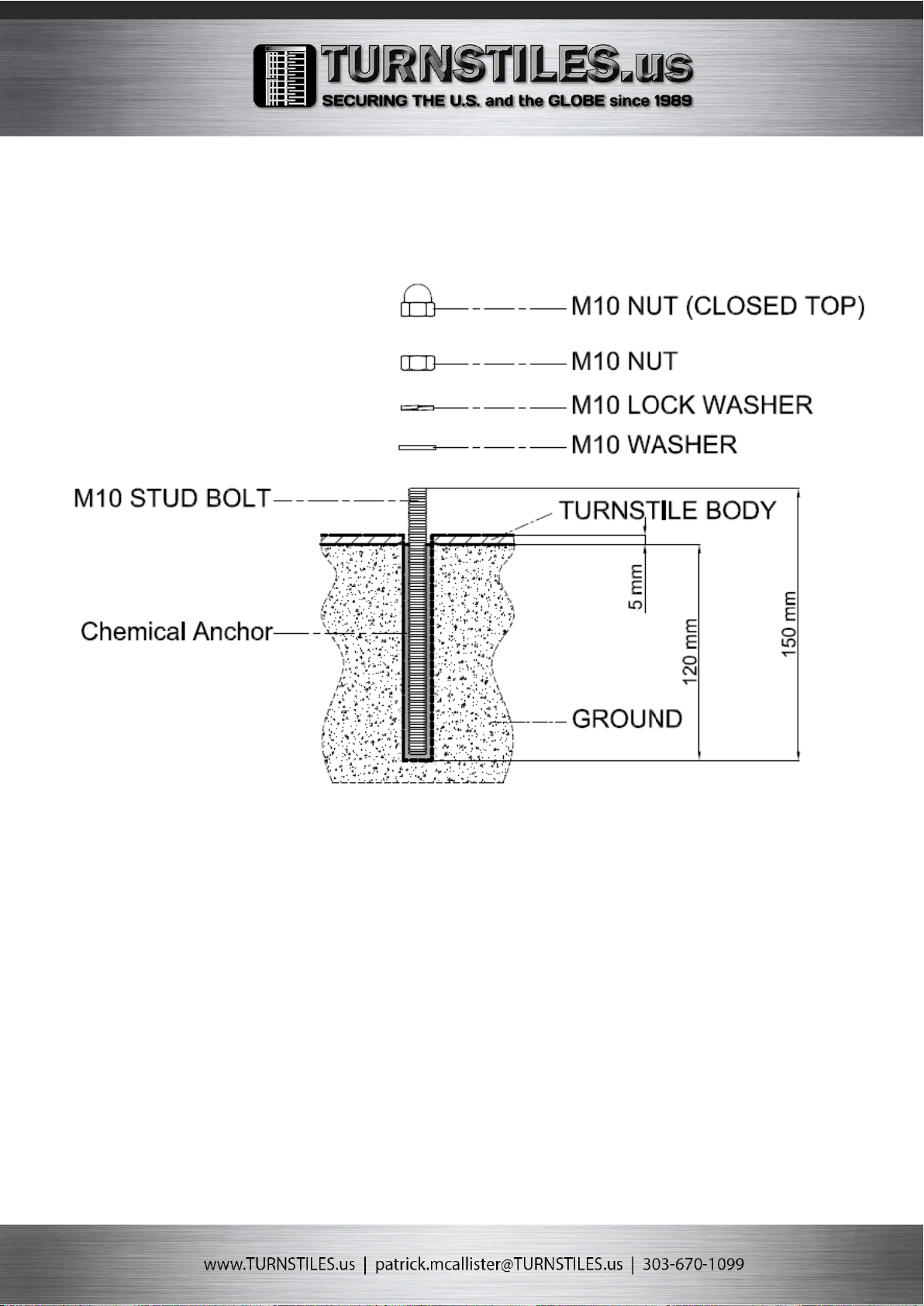
•DO NOT INSTALL THE DEVICE ON TO SURFACES THAT COULD YIELD AND
BEND. IF NECESSARY, ADD SUITABLE REINFOR CEMENTS TO THE
ANCHORING POINTS.
•ONLY INSTALL ON A LEVEL SURFACE.
•MAKE SURE ANY SPRINKLER SYSTEMS CAN NOT WET THE DEVICE FROM
THE GROUND UP.
INSTALLATION SAFETY
•SUITABLY SECTION OFF AND DEMARCATE THE ENTIRE
INSTALLATION SITE TO PREVENT UNAUTHORIZED PERSONS FROM
ENTERING THE AREA, ESPECIALLY MINORS AND CHILDREN.
•THE DEVICE MUST BE CONNECTED TO AN EFFICIENT, PROPER
GROUNDING SYSTEM.
•TANSA DECLINES ANY LIABILITY FOR USING NON-ORIGINAL
PRODUCTS; WHICH WOULD RESULT IN WARRANTY LOSS.
•APPLY WARNING SIGNS WHERE NECESSARY AND IN A VISIBLE
PLACE.
•ESD (ELECTROSTATIC DISCHARGE) REFERS TO THE MEASURES
TAKEN TO PROTECT COMPONENTS VULNERABLE TO ELECTROSTATIC
DISCHARGES AGAINST SUCH DISCHARGES AND HENCE FROM
POTENTIAL DAMAGE OR DESTRUCTION.
CABLE CONNECTIONS
•NO CABLES MAY BE CONNECTED OR DISCONNECTED DURING A
STORM (DANGER OF BEING STRUCK BY LIGHTNING).
•WHEN CONNECTING OR DISCONNECTING ANY OF THE LEADS,
ALWAYS HOLD THEM BY THE PLUG.
•NEVER PULL ON THE CABLES THEMSELVES. DOING SO COULD
CAUSE A CABLE TO BECOME DETACHED FROM THE PLUG.
•LAY THE CABLES SO THAT THEY DO NOT PRESENT A DANGER
(TRIPPING) AND CANNOT BE DAMAGED, BY BEING BENT, FOR
INSTANCE.
•PLEASE CHECK DEVICES WITH ADJUSTABLE RATED VOLTAGE TO
DETERMINE WHETHER THE PRESET RATED VOLTAGE OF THE DEVICE
CONFORMS TO THE LOCAL MAINS VOLTAGE. AN INCORRECT
SETTING MAY LEAD TO DAMAGE TO OR DESTRUCTION OF THE
DEVICE.
•BEFORE OPERATING, CHECK WHETHER ALL THE CABLES AND
WIRES ARE IN A PERFECT, UNDAMAGED CONDITION.
•ENSURE IN PARTICULAR THAT THE CABLES HAVE NOT BEEN BENT,
HAVE NOT BEEN LAID TOO TIGHTLY ROUND CORNERS, AND THAT
THERE ARE NO OBJECTS LOCATED ON TOP OF THEM. ALSO MAKE
SURE THAT ALL CONNECTORS HAVE A TIGHT FIT. DEFECTIVE
SCREENING OR WIRING MAY DAMAGE YOUR HEALTH (ELECTRIC
SHOCK) AND CAN DAMAGE OTHER DEVICES.
•THE SYSTEM EARTHING (EARTH WIRE) IS CONNECTED TO THE
PEDESTAL ENCLOSURE. THE EARTHING OF THE ENCLOSURE IS NOT
REQUIRED FOR ELECTRICAL SAFETY, ALTHOUGH THIS MAY BE
REQUIRED TO CONFORM TO CERTAIN STANDARDS.
•MAKE SURE THAT NO OBJECTS (E.G. JEWELLERY, PAPER CLIPS,
ETC.) OR LIQUIDS GET INSIDE THE DEVICE. THIS CAN LEAD TO
ELECTRIC SHOCKS OR SHORT-CIRCUITS.
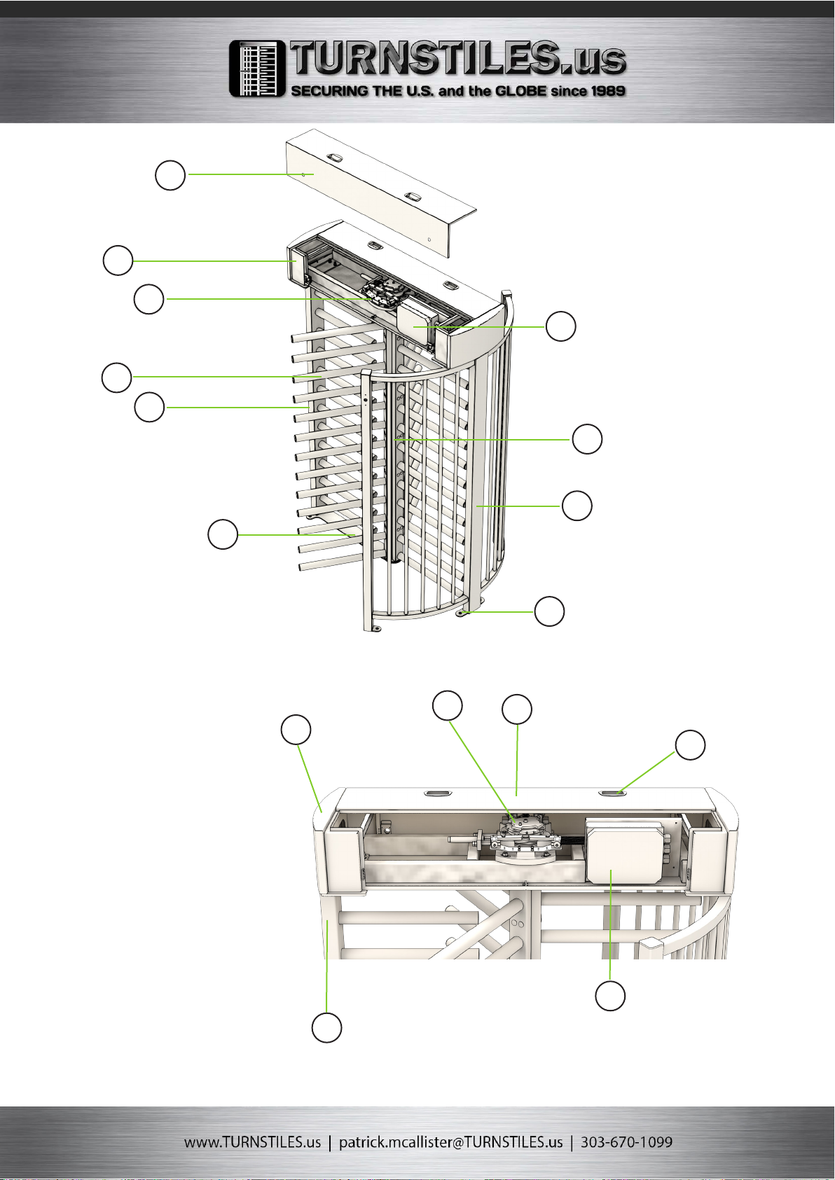
•PROPER OPERATION AND COMPLIANCE WITH THE EMC
(ELECTROMAGNETIC COMPATIBI-LITY) LIMIT VALUES IS ONLY
GUARANTEED WHEN THE ENCLOSURE IS MOUNTED CORRECTLY AND
THE SIDE PANELS ARE IN PLACE.

•IN THE EVENT OF A MALFUNCTION OR SERVICING, THE DEVICES NEED
TO BE DISCONNEC-TED FROM THE MAINS IMMEDIATELY. IF DEVICES ARE
CONNECTED TO ONE OR MORE UNIN-TERRUPTIBLE POWER SUPPLIES
(UPS), THEY WILL CONTINUE TO OPERATE EVEN IF THE PLUG TO THE UPS
IS PULLED. YOU THEREFORE NEED TO SHUT DOWN THE UPS IN
ACCORDANCE WITH THE APPROPRIATE USER DOCUMENTATION.
•PERMANENT WIRING IS TO BE EMPLOYED AS REQUIRED BY LOCAL
CODES.
DURING OPERATION & USE
•KEEP TURNSTILE OPERATION AREAS CLEAN AND FREE OF ANY
OBSTRUCTIONS.
•DO NOT ALLOW CHILDREN TO PLAY WITH FIXED COMMANDS, OR TO
LOITER IN THE TURNSTILE’S MANEUVERING AREA. KEEP ANY REMOTE
CONTROL TRANSMITTERS OR
ANY OTHER COMMAND DEVICE AWAY FROM CHILDREN, TO PREVENT THE
OPERATOR FROM BEING ACCIDENTALLY ACTIVATED.
•THE APPARATUS MAY BE USED BY CHILDREN OF EIGHT YEARS AND
ABOVE AND BY PHYSICALLY, MENTALLY AND SENSORY-CHALLENGED
PEOPLE, OR EVEN ONES WITHOUT ANY EXPERIENCE, PROVIDED THIS
HAPPENS UNDER CLOSE SUPERVISION OR ONCE THEY HAVE BEEN
PROPERLY INSTRUCTED TO USE THE APPARATUS SAFELY AND TO THE
POTENTIAL HAZARDS INVOLVED.
•CLEANING AND MAINTENANCE BY USERS MUST NOT BE DONE BY
CHILDREN, UNLESS PROPERLY SUPERVISED.
•FREQUENTLY CHECK THE SYSTEM FOR ANY MALFUNCTIONS OR SIGNS
OF WEAR AND TEAR OR DAMAGE TO THE MOVING STRUCTURES, TO THE
COMPONENT PARTS, ALL ANCHORING POINTS, INCLUDING CABLES AND
ANY ACCESSIBLE CONNECTIONS.
•KEEP ANY HINGES, MOVING JOINTS AND FRICTION POINTS PROPERLY
LUBRICATED.
•KEEP AWAY FROM AND DO NOT LOITER NEAR THE BARRIER AND
MECHANICAL MOVING PARTS.
•DO NOT ENTER THE BARRIER’S AREA OF OPERATION WHEN IT IS
MOVING.
•DO NOT COUNTER THE OPERATOR’S MOVEMENT AS THIS COULD
RESULT IN DANGEROUS SITUATIONS.
•ALWAYS PAY SPECIAL ATTENTION TO ANY DANGEROUS POINTS, WHICH
HAVE TO BE LABELED WITH SPECIFIC PICTOG RAMS AND/OR BLACK AND
YELLOW STRIPES.
•WHEN USING A SELECTOR SWITCH OR A COMMAND IN MAINTAINED
ACTION MODE, KEEP CHECKING THAT THERE ARE NO PERSONS WITHIN
THE OPERATING RANGE OF ANY MOVING PARTS, UNTIL THE COMMAND IS
RELEASED.
•THE TURNSTILE MAY MOVE AT ANY TIME AND WITHOUT WARNING.
MAINTANENCE SAFETY
•ALWAYS CUT OFF THE MAINS POWER SUPPLY BEFORE
PERFORMING ANY MAINTENANCE OR CLEANING.
•WHEN REPAIRING OR MODIFYING THE DEVICE, USE ONLY
APPROVED PARTS. FAILURE TO OBSERVE THIS RULE CAN LEAD TO
VIOLATION OF THE ELECTROMAGNETIC COMPATIBILITY (EMC) OR
SAFETY STANDARDS AND CAUSE DEVICE MALFUNCTIONS.
•IF THE POWER SUPPLY CABLE IS DAMAGED, IT MUST BE
REPLACED BY THE MANUFAC-TURER OR AUTHORIZED TECHNI CAL
ASSISTANCE SERVICE, OR IN ANY CASE, BY SIMILARLY QUALIFIED
PERSONS, TO PREVENT ANY RISK.
•THE DEVICE MAY ONLY BE REPAIRED BY AUTHORISED,
QUALIFIED PERSONNEL. IMPROPER REPAIRS MAY EXPOSE THE
USER TO CONSIDERABLE DANGER (ELECTRIC SHOCK, FIRE).
•IT IS FORBIDDEN FOR USERS TO PERFORM ANY OPERATIONS THAT
ARE NOT EXPRESSLY REQUIRED OF THEM. FOR ANY REPAIRS,
MODIFICATIONS AND ADJUSTMENTS AND FOR EXTRA-ORDINARY
MAINTENANCE, CALL TECHNICAL ASSISTANCE.
•UNAUTHORISED OPENING OF THE DEVICE OR INDIVIDUAL PARTS OF
THE DEVICE CAN ALSO EXPOSE THE USER TO DANGER. UNAUTHORISED
OPENING OF THE DEVICES OR PARTS THEREOF RESULTS IN VOIDING
OF THE WARRANTY AND EXCLUSION OF LIABILITY.
•DISCHARGE STATIC (E.G. BY TOUCHING AN EARTHED OBJECT)
BEFORE TOUCHING THE PCB. ONLY USE TOOLS AND DEVICES THAT ARE
FREE FROM STATIC CHARGES.
•BEFORE INSTALLING OR REMOVING PARTS, REMOVE THE POWER
SUPPLY.
•AVOID TOUCHING THE PINS OR CONDUCTOR TRACKS OF PCBS; TRY
TO HOLD THEM BY THE EDGES.
•THE MAINTENANCE SCHEDULE FOR THESE PRODUCTS IS TO INCLUDE
A 6-MONTH INSPECTION AND 12-MONTH MAINTENANCE PROCEDURE,
AS ADVISED BY THE MANUFACTURER.
CLEANING
•THE UNIT MUST NOT BE WET CLEANED. WATER ENTERING THE UNIT
COULD REPRESENT CONSIDERABLE DANGER FOR THE OPERATOR (E.G.
ELECTRIC SHOCK).
•IF ANY, PLEASE CLEAN THE INFRARED (IR) WINDOWS REGULARLY
(RECOMMEND ANNUAL-LY). DIRTY WINDOWS CAN CAUSE FALSE
ALARMS OR RESULT IN UNAUTHORISED PERSONNEL TO GAIN ACCESS
INTO THE SECURE AREA. IR WINDOWS MUST BE CLEANED INSIDE AND
OUT.
•NEVER USE SCOURING CLEANSERS, ALKALINE DETERGENTS, SHARP
OR SCOURING CLEANING AIDS. THIS MAY RESULT IN DAMAGE TO THE
SURFACE OF THE DEVICE. THE SAME APPLIES FOR PARTS INSIDE.
•DO NOT USE ANY CHEMICAL OR CLEANING SOLUTIONS NEXT TO THE
DEVICE, AND MAKE SURE SUCH MATERIALS ARE NOT KEPT THERE.
THEY MAY DAMAGE THE DEVICE.
THIS UNIT CONTAINS PARTS THAT ARE SUITABLE FOR
RECYCLING, AND COMPONENTS THAT REQUIRE SPECIAL
DISPOSAL. YOU ARE REQUESTED TO TAKE SUITABLE
MEASURES TO ENSURE THE PRODUCT WILL BE RECYCLED
AT THE END OF ITS SERVICE LIFE.

FEATURES
• Portal and housing made of steel
• Portal turnstile, four-part rotor blade with spars, 90°division
OR three-part rotor, 120° division
• As standard with 13 rod-shaped crossbars with plastic caps
on each section of the rotor. Arm diameter 51mm
• Rotor with 13 rod-shaped bars made of steel
•Limitation of passage: with steel filler rods
•Unidirectional or bidirectional operation
• Completely assembled or disassembled delivery as a kit for
easier transport or for places that are difficult to access.
• Lockable maintenance lid with top and side opening for easy
maintenance and installation in areas with low ceilings.
• In addition to the turnstile: Motorized or manually operated
pedestrian door in full height (bi-directional)
DRIVE MECHANISM OPTIONS
• Elektromechanic / Hand operated
• BLDC Motor-driven
• A self centring mechanism to ensure complete rotation of
the mechanism to the home position.
• A hydraulic damper to ensure smooth operation
• Anti backup device to prevent reverse rotation once the
mechanism has moved 30 degrees from the home position
• Fail-safe operation as standard. (Optional fail-locked)
FUNCTIONS & INTERFACE
• Logic controlled interface, bi-directional operation
• Entrance and exit directions can be individually set as
controlled, locked or free before or after the installation.
• In controlled access mode, after release conrmation which
was sent by access control system, the turnstile unlocks
the released direction and enables one person access in the
direction of travel. After each person, the turnstile rotor
blocks passage again and does not permit access from both
entrance and exit directions until receiving a new release
signal from the access control system.
• After the release, the turnstile blocks itself after an
adjusted time if no transition or passage occures.
• If people from both directions would like to pass through
simultaneously, the rst person who activates the turnstile
takes precedense.
• Multiple opening: An additional person is able to to release
the next passage cycle during an ongoing passage cycle in
both directions. The turnstile controller stores up to 255
releases and lets corresponding number of individuals pass
through.
• Relay outputs for counting passage in either direction
• RS 232 serial port
• Control for inputs and outputs via potential-free contact
EMERGENCY & POWER CUT
In the event of emergency or power-cut the mechanism
unlocks the rotor and the rotor rotates freely in both
directions. The turnstile reset itself automatically when the
emergency alarm stops or the power is switched back on.
LED INDICATORS
LED lights indicates the operating status of the turnstile in both
directions.
Option-1 Option-2
Green: Standby or locked Released or free passage
Red: Released or free passage Standby or locked
SETTINGS
Operation mode for each directions : Controlled / Free / Locked
Acoustic Notications : On/Off
Release time out : 5-10-15-20 secs
Consecutive passage : On/Off
Emergency connection : On/Off
LED Indicator options :Option-1/Option-2
SPECIFICATIONS:
Construction: Steel
Passage width: 670 standard (26.4 in)
Weight: 490 Kg (1080 lb)
Power Supply: 100 - 240 VAC, 50/60 Hz
Logic Voltage: 24V DC
Standby power consumption: 12 W
Operation Temperature: -10 ° / +70 °
IP Protection: Cabinet IP54 / Logic Controller IP65
MATERIAL OPTIONS
• Galvanized
• Galvanized + Powder coated
• AISI 304 Stainless steel
• AISI 316 Stainless steel
• Stainless steel rotor & Powder coated frame
ACCESSORIES:
• Access Controller mounting plate
• Access Controller Box
• Ceilig lights
• LED indicators
• Heating kit for -40 degrees
• Roof & Canopy
• Tempered glass side panels
• Mounting plate (suitable for forklift transport)
• Mounting frame for pre-installation into concrete
• Back-up battery 7A
• Access controller integration options
(Please contact with sales represantative for full list of options
and accessories)
OST Full Height Mechanical Single Turnstile

3 sectional (120°) and 13
horizontal arms in 51 mm
diameter in each section
2370 mm / 93,31” (Standard)
2460 mm / 96,85” (Motor driven)
2430 mm / 95,67”
2125 mm / 83,66”
670 mm / 25,54”
683 mm / 26,90”
Rotor:
Complete Height:
Complete Width:
Passage Height:
Passage Widht:
Entrance Widht:
OST Full Height Mechanical Single Turnstile

1. Removable lid
2. Keylocked Cabinet / Housing
3. Mechanism
4. Rotor arms
5. Barrier comb
6. Bottom bearing plate
7. IP67 Electronics box
8. Rotor
9. Yoke with filler rails
10. Installation locations
11. Lid handles
1
2
3
4
5
6
7
8
9
10
11
1
2
3
4
5

2. Opening the lid

3. Ground Installation

1. Sensor plate
2. Lock plate
3. Cast and machined aluminium mechanism plate
4. Hydrolic shock-absorber to ensure smooth operation
5. Lock arms
6. 24V solenoid/electromagnetic lock
7. Proximity sensor for direction control
8. Anti backup device to prevent reverse rotation once the the mechanism
has moved 30 degrees from home position.
9. Shock-absorber balancing spring.
4. Full Height Mechanism
1
2
3
45
6
7
8
9

5. TEC 101 Logic Controller Board Connections


ELECTRICAL CONNECTIONS
Control card 1and specifications
Open the electronic card box on the corner of the turnstile slowly by pressing lightly on the right and left sides to see the TEC-101 control
card. When closing the cover of the card box, please pay attention to the electric cables.
The circuit diagram of the control card in the turnstile is as in Figure 5.2. The software and functional equipment of the control card vary
according to the turnstile model. All components on the control board consist of components to operate in industrial environment.
The LEDs on the electronic card show the operation status of the card in group 1 in Figure 5.1.1. The green LED flashes continuously. This
indicates that the card processor is working properly. The other red LEDs are power LEDs. These LEDs show the presence of energy by
flashing.
The label on the control card shows the mode of operation and version of the turnstile. Therefore, it should not be disassembled.
Figure 5.1 shows the protective plastic box of the control board. On the membrane label located on the box, the connection diagrams of the
input and output terminals and the functions of the switches are explained. There is a reset button on the card to restart the control card.
There is a hole for access to the reset button, and you can reach the reset button by using a screwdriver to reset the device.
The TEC-101 turnstile control card has LEDs on all inputs and outputs. It can be monitored that the input or output related to these LEDs is
working electronically.
The following figure shows the status and functions of the LEDs located on the control card.
Figure 5.1 Electronic Card Box
Figure 5.1.1 Control Card LED Layout

1- These LEDs indicate the internal operating voltages of the turntable, that are + 5V and + 24V, and that the turnstile works. The function
of the corresponding LED is written on it. During the breakdown, first it should be checked whether the + 24V LED is on, then the + 5V LED
should be checked. If the + 5V LED is off the control card is defective and must be changed without any interference. The Run LED indicates
that the processor of the control card is working. The Run LED flashes during normal operation, if it is continuously on or off, the control
board is faulty.
2- The LEDs in this block indicate whether the equipment is working by checking the solenoid outputs. The L19 and L20 LEDs turn green
continuously when the solenoid is locked, and they must turn off in free mode or during passing.
3- The L8 LED in coin-operated turnstile models show whether the coin unit has an external +12V power supply connection.
4- The most important LEDs in this group are sensor LEDs. The operation of 2 direction sensors located on the mechanism is controlled
by these LEDs. The SensA and SensB LEDs are on when the turnstile arm is in the middle position at idle, and they are all turned off when
sensor disc passes through the sensors while the turntable arm rotates. If the sensor LEDs are all off or on during arm rotation, there may
be a malfunction in the sensors or connection points.
In very dusty environments, the inside of the sensors can be cleaned first with a fine brush and then with a damp cloth.
5- 4 LEDs (Ain, Bin, Oin, Emr) indicate whether the external inputs are working or not. The emergency input LED (Emr) must be permanently
on unless there is an emergency. Ain, Bin, Oin will be on as long as there is a signal in the input. If these LEDs on 3 inputs are always on, it
means that NC “normally closed” contact signal is connected to external inputs or that there is a connection error.
6- There is a dry corac relay output in the direction of pass after the arm rotation. The LEDs placed in front of these roles are turned on and
off together with the 500mS relay after passing, so that it is understood that the relay is working and there is contact.
7- The LEDs in this group show the operation stop of the control LEDs at the entrance and exit of the turnstile. When the corresponding LED
is on, it is understood that the guiding LED is working. Red / Green LEDs are used for direction A and direction B.
8- L21 LED is used in turnstiles with drop arm option. It turns on when the arm dropping motor is powered, and remains off at the other
time.

Figure 5.2 TEC101 Control Card
1. Motherboard supply input (+24VDC)
2. (Option) drop arm motor connection
3. A direction / B direction LED indicator connector
4. Guiding indicators (Indicator LED)
5. A direction / B direction pass information NO / NC selection jumper
6. A direction / B direction pass information relay output connector
7. Control inputs connector
8. Emergency parallel connection jumper
9. Emergency active / passive jumper
10. Control inputs indicator LED
11. Option input
12. Sensor inputs indicator LED
13. Sensor Inputs
14. Coin connection connector
15. B solenoid connection connector
16. A solenoid connection connector
17. On / off function switch
18. Serial connection connector
19. Reset switch
20. Power LED indicator
21. Programming socket
22. Buzzer

Figure 5.3 Function switch
Control card switch descriptions
The functions of the on / off function switches (number 17 on the control card) seen in figure
5.3 above are as follows:
The switches are ON in Figure 5.3.
Automatic shutdown time: It is determined by the switch 1 and switch 2. It is the waiting
time setting for the person to pass, corresponding to the “open” signal coming from the controller
to the turnstile. If the person passes just after the open signal, the waiting time is cancelled and the
turnstile is locked.
Passing direction control: It is determined by the switch 3 and switch 4. One or both of the
desired directions of the turnstile designed for two-way controlled transition can be set to
continuous free pass mode. The guiding led in the direction of free pass will be green.

Continuous pass with entry signal: It is determined by the switch 6. With this mode, if A direction, B direction and common input signals are received
continuously without interruption, continuous passing is allowed. In some reader models, it is used when the relay trigger times are long and the reader
signal is continuous in successive passes.
Passing Direction and Guiding LED Operation Mode Selection in Coin Operated Mode: With switch 7, both the coin-ejection direction is selected in coin
operated mode, and the functioning of guiding LEDs can be changed as Green at idle or Red at idle. In coin operated turnstiles, it adjusts passing in direction
A or B direction with coin.
Audio Warning On/Off: It is determined by the switch 8. After the “open” command coming from the control system to the turnstile, it gives intermittent
audio signal until passing or automatic closing. It is recommended to be used to make the users understand that they are allowed to pass.
Memory mode selection: It is determined by the switch 5. In standard turnstiles, after the entry signal is received, the input (Ain, Bin, Oin) is inactive and the
incoming signals are not processed until passing is completed or the automatic closing is activated. With the memory mode, all entry signals (up to 200) are
saved in the memory even during passing. With this mode, the turnstile can be operated in full capacity.

.
Control card terminal descriptions (XL5)

Normally open (NO)) role / pushbutton contacts must be connected to control inputs, the normally closed
(NC) contact should never be connected. If the normally closed (NC) contact is used instead of the
normally open (NO) contact, there will be problems such as the turnstile delaying the passing permission.
If it is used with this problem, the turnstile may be damaged as it will result in hitting the arms.
Normally closed (NC) contact connection is required for emergency. The J2 jumper (Fig. 5.5) is inserted when the turnstile is shipped from the factory. If the
alarm contact is to be used, this short circuit jumper (J2) must be removed.
Triggering with power input (PNP)
The opening to direction A input in the XL5 connector can also be controlled by the opening
to direction B input and the emergency connection input + V (PNP). A voltage between +12 VDC
and +24VDC can be used. In the case of the use of a PNP output card reader, fingerprint reader,
palm reader and similar hardware, this connection type can be used. The pin 2 of terminal XL5
can be used to control passing to direction A, and the pin 3 can be used to control passing to direction B.
The reader system’s V- (GND) must be connected to pin 6 of the XL5 terminal. (Figure 5.6)
External connection types
Triggering with dry contact
As shown in Figure 5.4, the pin 1 of the XL5 terminal is used as the common pole with + 24VDC voltage. The pin 2 is used as opening to direction B, and the
pin 3 is used as the opening to direction B inputs. In the normally open (NO) dry contact connection, +24VDC from the pin 1 is transferred to the pin 2 or
the pin 3 via the relay contact or the pushbutton to allow passing.

As the emergency input is the NC contact input, J2 pins are equipped with a short circuit jumper. If the emergency input is to be
used, the J2 jumper must be removed and replaced with the emergency contact from the alarm panel. As long as the emergency
input is active, the turnstile rotates freely in both directions. When an emergency signal is received in drop arm turnstiles, the
arm in the middle position drops and allows passing. When the emergency state is passive again, the dropped arm must be lifted
manually.
Alarm cable group turnstile connection
The emergency contact from the alarm panel (Normally closed - NC) must be connected to the first turnstile in a group of turnstiles. The other turnstiles
must have a 2x0.50mm alarm cable connecting one with another in sequence. An emergency connection can be made with a single contact by grouping
as many turnstiles as desired. The J2 jumpers on the control card of the turnstiles to have emergency connection must be removed. Normally closed (NC)
contact is required from the alarm panel in the following connection. As shown in the diagram, the J1 jumper is installed on the control board in the first
turnstile with alarm cable, while it is not installed on other turnstiles. If installed, it must be definitely removed. (Figure 5.7) Pin 6 (GND) of terminal XLS of
turntables are connected to each other, and the pin 5 emergency inputs are connected to each other. Finally, the emergency contact from the alarm
panel is connected to pin 1 (+ 24VDC) and pin 5 of terminal XL5.

Technical Do
Control card terminal descriptions (XL9)
XL9 terminal has direction A and B pass relay contacts. (Figure 5.8)
Relay contacts are normally open (NO) when the turnstile is at idle.
The pins 2 and 3 of terminal XL9 are connected to the relay RL1.
The relay RL1 is active in passing to direction A. The pins 4 and 5
of terminal XL1 are connected to relay RL2. The relay RLw is active
in passing to direction
B.
The signal duration of the relays giving the pass information is
500mS. The corresponding relay pulls and releases at 500mS in
each pass. The normally open (NO) and common (COM) poles of the
RL1 and RL2 pass relays are removed in the factory as standard.
If normally closed (NC) contact outputs are to be taken, J3 and J4
jumper should be removed from the
Table of contents
Other Turnstiles Turnstile manuals

Turnstiles
Turnstiles HS400 Series User manual

Turnstiles
Turnstiles mWing User manual

Turnstiles
Turnstiles TPW-321ASP User manual

Turnstiles
Turnstiles HZ-SLBS02 User manual

Turnstiles
Turnstiles HZ-FHTS05 User manual

Turnstiles
Turnstiles AG Series User manual

Turnstiles
Turnstiles HZ-SWGS01 User manual

Turnstiles
Turnstiles HZ-FHTS03 User manual

Turnstiles
Turnstiles OMD22 User manual

Turnstiles
Turnstiles DS7200 User manual