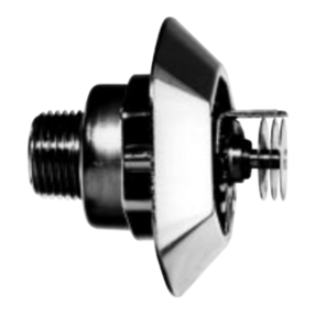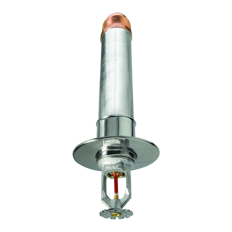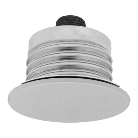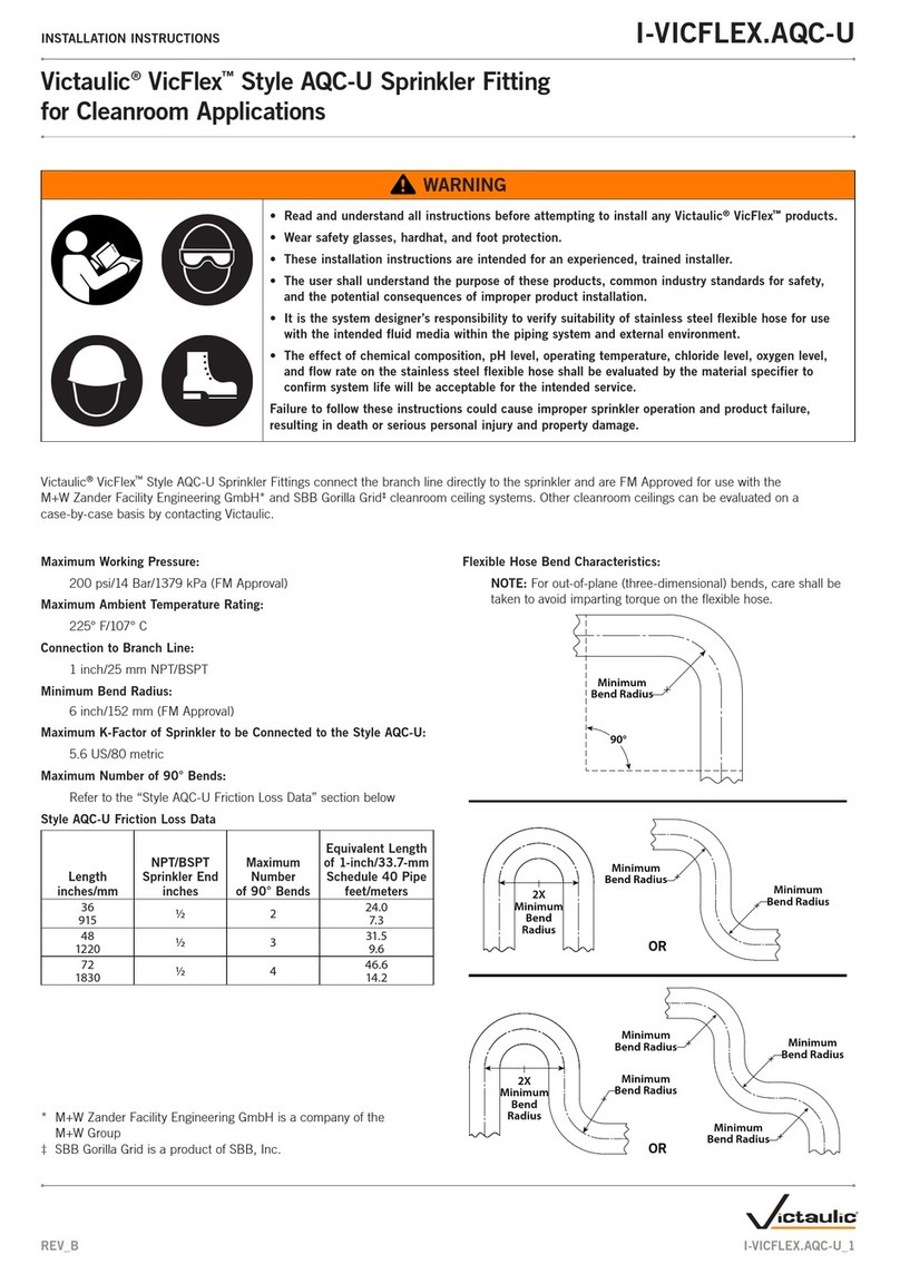
Table 1 - LF Horizontal Sidewall and Recessed Horizontal
Sidewall Sprinkler Design Requirements for
NFPA 13D & NFPA 13R Occupancies
Minimum Design Flow (Pressure)
Coverage Multiple Deflector Temperature
Area Single Sprinkler Sprinklers Distance
*12' x 12' 14 GPM/16.0 psi 11 GPM/9.9 psi 4" - 12" 155°F/68°C
(3,7 m x 3,7 m) (53,1 lpm / 1,1 bar) (41,7 lpm / 0,7 bar)
175°F/79°C
*14' x 14' 14 GPM/16.0 psi 12 GPM/11.8 psi 4" - 12" 155°F/68°C
(4,3 m x 4,3 m) (53,1 lpm / 1,1 bar) (45,5 lpm / 0,8 bar)
175°F/79°C
*16' x 16' 16 GPM/20.9 psi 13 GPM/13.8 psi 4" - 6" 155°F/68°C
(4,9 m x 4,9 m) (60,6 lpm / 1,4 bar) (49,3 lpm / 1,0 bar)
175°F/79°C
‡16' x 16' 19 GPM/29.5 psi 18 GPM/26.4 psi 6" - 12" 155°F/68°C
(4,9 m x 4,9 m) (72 lpm / 2,0 bar) (68,2 lpm / 1,8 bar)
‡16' x 18' 19 GPM/29.5 psi 18 GPM/26.4 psi 4" - 12" 155°F/68°C
(4,9 m x 5,5 m) (72 lpm / 2,0 bar) (68,2 lpm / 1,8 bar)
* These flows and pressures are applicable for Smooth, Flat, Ceilings with
a Max. 8:12 Slope.
‡ These flows and pressures are applicable for Smooth, Flat, Ceilings with
a Max. 2:12 Slope.
Design
Criteria
Installation
The Central Model LF Horizontal Sidewall
Sprinklers must be installed in accordance
with the following instructions:
NOTES
Do not install any bulb type sprinkler if the
bulb is cracked or there is a loss of liquid
from the bulb. With the sprinkler held
horizontally, a small air bubble with an
approximate diameter of 1/16 inch should
be present.
A leak tight 1/2 inch NPT sprinkler joint
should be obtained with a torque of 7 to 14
ft.lbs. (9,5 to 19,0 Nm). A maximum of 21
ft.lbs. (28,5 Nm) of torque is to be used to
install 1/2 inch NPT sprinklers. Higher
levels of torque may distort the sprinkler
Model LF Horizontal Sidewall and
Recessed Horizontal Sidewall Sprinklers
are UL, C-UL Listed and NYC Approved
(MEA 323-98-E) for use in accordance
with current NFPA standards for use on
wet pipe sprinkler systems. These
sprinklers have been investigated for use
under smooth flat horizontal ceilings with
slopes up to 2 inches per foot, at spacings
up to 16 feet by 18 feet, using the design
requirements found in Table 1. These
sprinklers have also been investigated for
use under smooth flat sloping ceilings with
slopes up to 8 inches per foot, at spacings
up to 16 feet by 16 feet, using the design
requirements found in Table 1 as well as
the sloped ceiling "Specific Application
Design Criteria" found in Figure 1.
The Recessed Horizontal Sidewall
Sprinklers are only listed with the Series
BV Res./QR Recessed Escutcheon
Assembly.
The minimum required single and multiple
sprinkler flow rates for systems designed
to NFPA 13D or NFPA 13R occupancies
are given in Table 1. The single sprinkler
flow rate is the minimum required
discharge from the most hydraulically
demanding single sprinkler and, the
multiple sprinkler flow rate is the minimum
required discharge from each of the total
number of "design sprinklers" as specified
in NFPA 13D or NFPA 13R.
TIA 99-1 (Tentative Interim Ammendment)
with an effective date of May 22, 2000
states that the minimum required
discharge from each of the "design
sprinklers" for systems designed to NFPA
13 must be calculated based on delivering
a minimum design density of 0.1 gpm/sq.
ft. for each of the listed coverage areas
shown in Table 1. Consult the authority
having jurisdiction regarding the
application of this TIA to the currently
adopted NFPA 13.
Model LF Residential Horizontal Sidewall
and Recessed Horizontal Sidewall
Sprinklers must be installed using the
obstruction and minimum distance
between sprinkler criteria for extended
coverage sidewall sprinklers found the
current edition of NFPA 13.
NOTES
Residential Fire Sprinkler Systems
should only be designed and installed
by those competent and completely
familiar with automatic sprinkler
system design, installation procedures,
and techniques.
The sprinkler must be secured in
position by firmly fastening the
sprinkler system piping to the
structure. If the sprinkler is not
properly secured in position, reaction
forces resulting from sprinkler
operation could alter its orientation and
its water distribution pattern. The
sprinkler escutcheon cannot be used
to hold the sprinkler in position.
Several criteria may apply to the
installation and usage of each
sprinkler. Consequently, it is
recommended that the sprinkler
system designer review and develop a
working understanding of the
complete list of criteria prior to
initiating the design of the sprinkler
system.
Questions concerning sprinkler
installation and usage criteria, which
are not covered by the following
instructions, should be submitted to
Central Sprinkler. Include sketches
and technical details as appropriate.
In some instances, the requirements of
this document may concern
specifications which are more
stringent and which take precedence
over those specified in NFPA 13, NFPA
13D, NFPA 13R, or by the authority
having jurisdiction.
inlet with consequent leakage or impair-
ment of the sprinkler.
Step 1. The sprinkler must only be
installed in the sidewall position with the
centerline of the sprinkler parallel to the
ceiling and perpendicular to the wall. The
top of the deflector is to be positioned
towards the ceiling.
Step 2. After installing the BV Res./QR
Recessed Support Cup (or other accept-
able escutcheon, as applicable) over the
sprinkler pipe threads and with pipe thread
sealant applied to the pipe threads, hand
tighten the sprinkler into the sprinkler
fitting.
Step 3. Wrench tighten the sprinkler using
only a BV Sprinkler Wrench (1099). The
wrench recess of the BV Sprinkler Wrench
is to be applied to the sprinkler wrench
flats (Ref Figure 3).
Step 4. For Recessed Sidewall Sprinkler
Applications, a Protective Cap is available
which helps to prevent damage to the
sprinkler during ceiling/wall installation
and/or during application of the finish
coating of the ceiling/wall. Place the
Protective Cap over the Recessed
Support Cup and push it sideways until it
bottoms out against the sprinkler deflector.
NOTE
As long as the Protective Cap remains in
place, the system is considered to be "Out
of Service"
Step 5. After the ceiling/wall has been
completed , remove and discard the
Protective Cap. If the Sprinkler has been
damaged, replace the entire Sprinkler
assembly. Do not attempt to modify or
repair a damaged sprinkler.
Step 6. Push the outer ring of the
Recessed Escutcheon over the Re-
cessed Support Cup. If the Recessed
Escutcheon cannot be engaged with the
Support Cup or the Recessed Escutcheon
cannot be engaged sufficiently to contact
the wall, the Sprinkler Fitting must be
repositioned.

