into the system piping, as well as
through the Alarm Port to actuate the
system alarms.
As water flows into the system, the
Model FSV-1 Fail-Safe Valve (Item 5 -
Fig. 2A, also described in Technical
Data Sheet TFP1386) becomes pres-
surized and upon operation constantly
vents the DV-5 Diaphragm Chamber
so as to maintain the DV-5 Valve in the
open (operated) position until the sys-
tem is reset.
WARNING
The Model DV-5 Double Interlock Pre-
action System with Electric/Pneumatic
Actuation described herein must be
installed and maintained in compli-
ance with this document, as well as
with the applicable standards of the
National Fire Protection Association,
in addition to the standards of any
other authorities having jurisdiction.
Failure to do so may impair the per-
formance of the related devices.
The owner is responsible for maintain-
ing their fire protection system and de-
vices in proper operating condition.
The installing contractor or manufac-
turer should be contacted with any
questions.
Technical
Data
Approvals
UL and C-UL Listed. FM Approved.
Deluge Valve
Model DV-5.
Riser Check Valve
Model CV-1FR.
NOTE
1-1/2 inch (DN40) risers utilize a 2 inch
(DN50) Riser Check Valve in combina-
tion with the 1-1/2 inch (DN40) Model
DV-5 Deluge Valve.
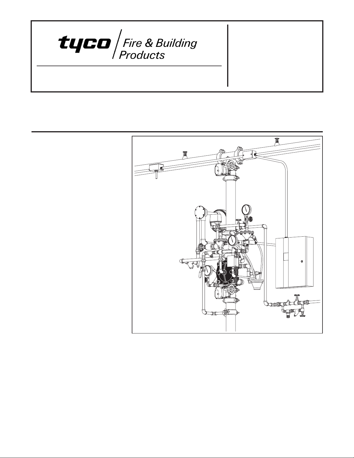
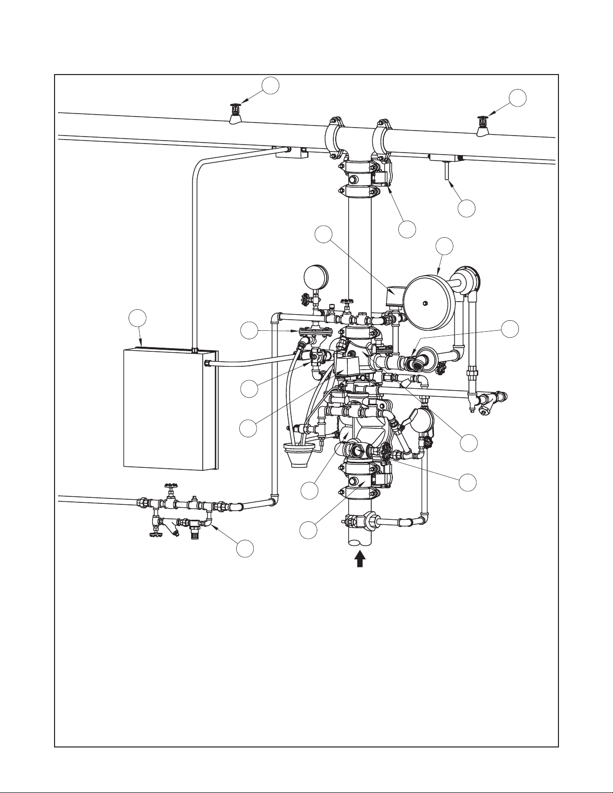
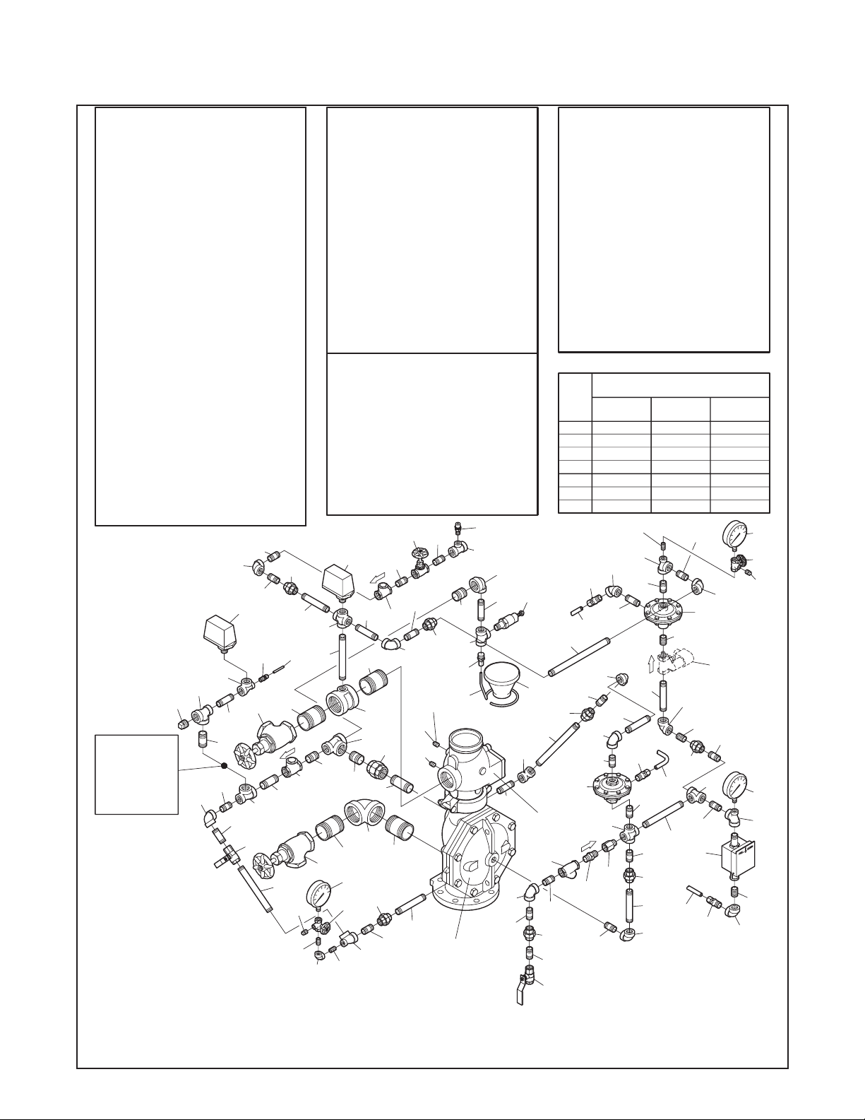
Valve Trim
The Double Interlock Preaction Sys-
tem with Electric/Pneumatic Actuation
Trim (Fig. 2A/2B) forms a part of the
laboratory listings and approvals. The
trim is necessary for proper operation
of the DV-5 Valve.
Each package of trim includes the fol-
lowing items:
•Water Supply Pressure Gauge
•Diaphragm Chamber
Pressure Gauge
•Diaphragm Chamber Connections
•Manual Control Station
•Main Drain Valve
•System Drain Valve
•Alarm Test Valve
•Automatic Drain Valve
•System Air Pressure Gauge
•Air Supply Connections
•Low Air Pressure Alarm Switch
•Waterflow Pressure Alarm Switch
•Dry Pilot Actuator
•Pressure Operated Relief Valve
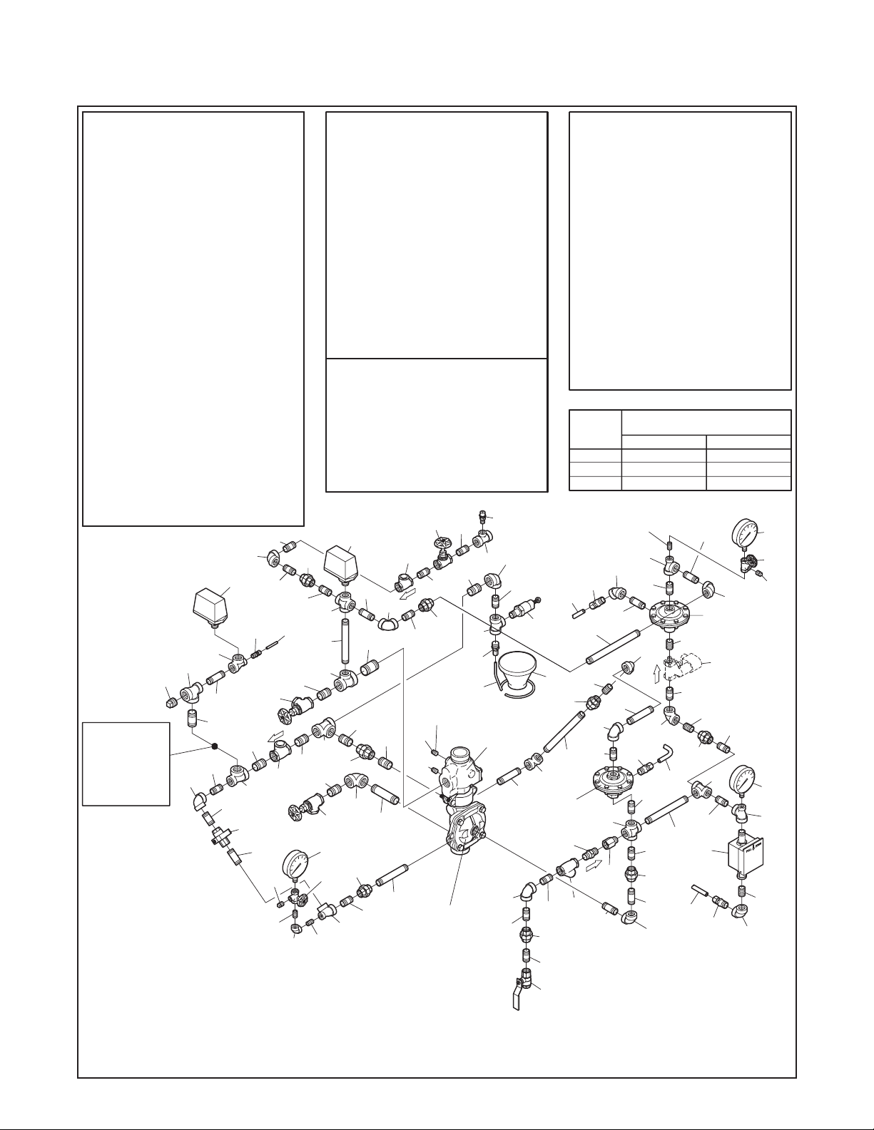
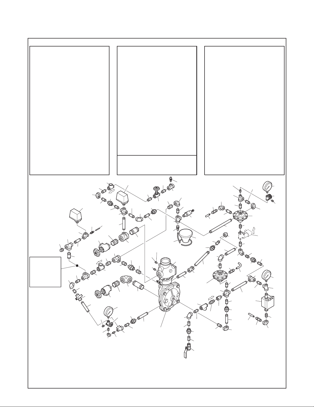
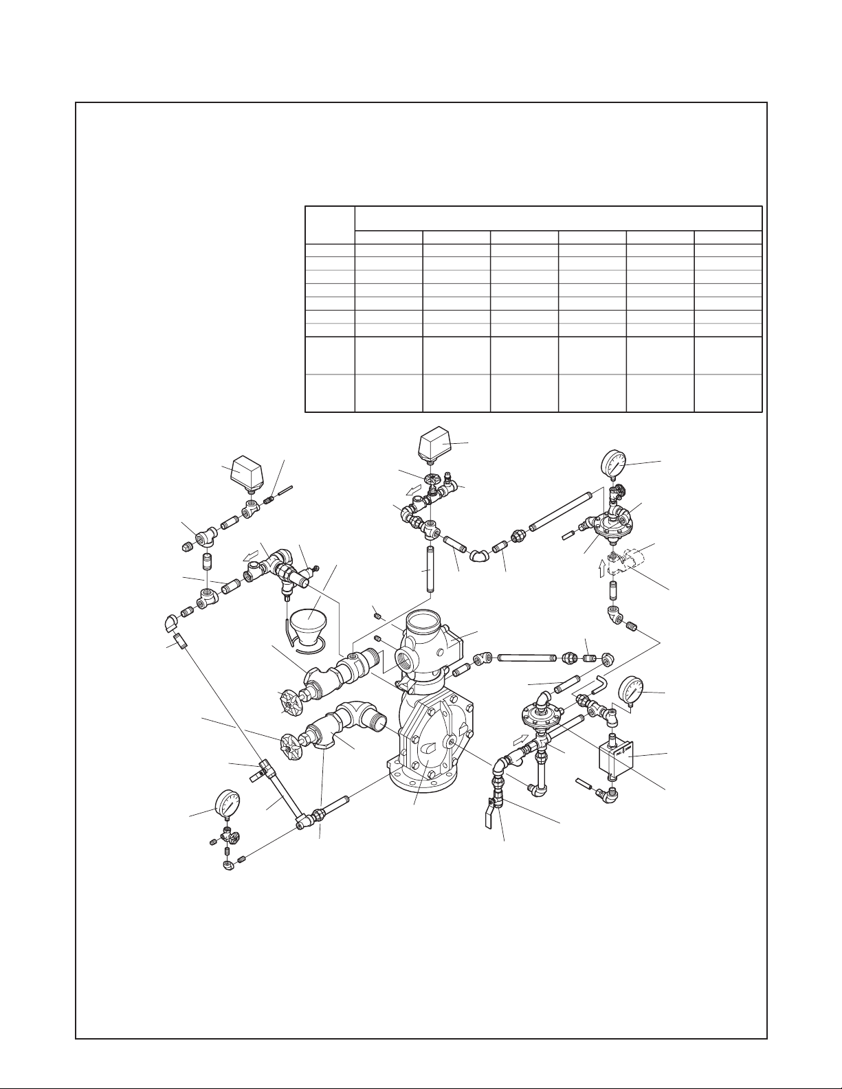
To ease field assembly of the trim ar-
rangement, the trim components are
provided partially assembled as
showninFigure2B.
The trim arrangement is provided with
galvanized or black nipples and fit-
tings. The galvanized trim is intended
for non-corrosive or corrosive condi-
tions, whereas the black trim is princi-
pally intended for use with AFFF sys-
tems.
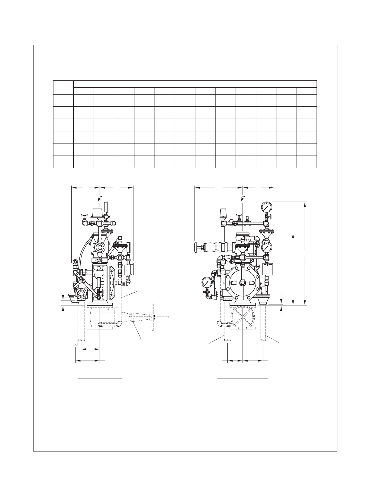
NOTE
When the system pressure is greater
than 175 psi (12,1 bar), provision is to
be made to replace the standard order
300 psi (20,7 bar) Water Pressure
Gauges, shown in Figure 2A/2B with
separately ordered 600 psi (41,4 bar)
Water Pressure Gauges.
System Design Considerations
Because a double interlock preaction
system requires time for a drop in sys-
tem air pressure to occur (concurrently
with the response time for the separate
fire detection system) before it will al-
low water to enter the system piping,
this system has characteristics similar
to a dry pipe sprinkler system. There-
fore, the system design considerations
for a dry pipe system are normally
applied to a double interlock preaction
system — including a 30% increase in
design area; a maximum 1 minute
water delivery time for system capaci-
ties of 750 gallons (2800 litres) or
more; and, prohibition of gridded sys-
tem piping.
In order to readily perform the System
Inspection Procedure described in the
Care and Maintenance section, it is
Page 9 of 16
TFP1460
GRAPH A
DOUBLE INTERLOCK PREACTION SYSTEM
AIR PRESSURE REQUIREMENTS
WATER S
PPLY PRESS
RE IN PSI
100
RANGE OF ACTUATOR OPENING PRESSURE
MINIMUM SYSTEM AIR PRESSURE
AIR PRESSURE IN PSI
20 60
15
0
30
45
140 180 250200