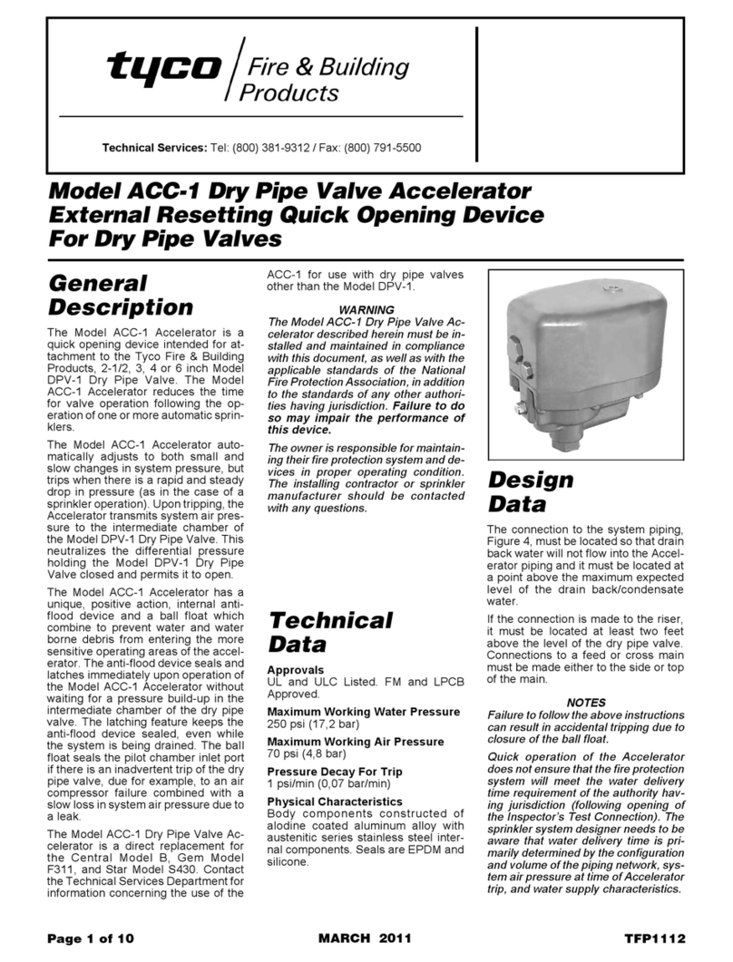
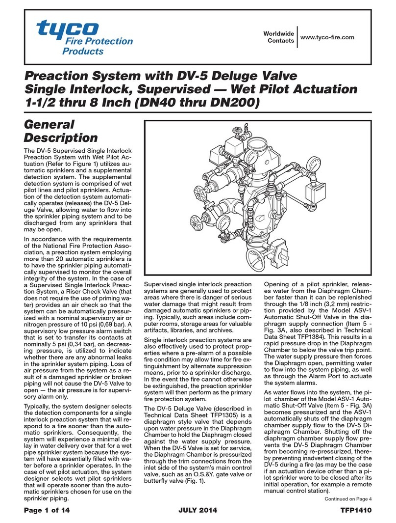
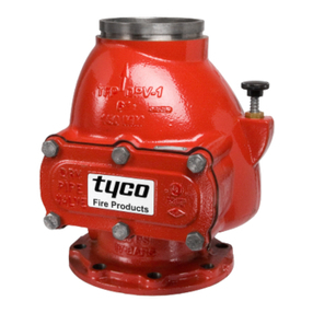
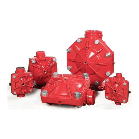
Tyco QRS User manual

Model QRS Electronic Accelerator
(Quick Opening Device)
For Dry Pipe or Preaction Systems
Page 1 of 16 SEPTEMBER 2021 TFP1100
Worldwide
Contacts
www.tyco-fire.com
IMPORTANT
Refer to Technical Data Sheet
TFP2300 for warnings pertaining to
regulatory and health information.
General
Description
The TYCO Model QRS Electronic
Accelerator is a quick opening device
intended to reduce the operating time
of a dry pipe valve in a dry pipe system
or an automatic control valve (deluge
valve) in a double interlock electric/
electric preaction system.
The control panel for the QRS may be
used with up to four QRS switches for
one to four system risers using one of
the following dry pipe valves:
•
TYCO 4 in. & 6 in. (DN100/150)
Model DPV-1 Dry Pipe Valves
•
Central 3 in. (DN80) Model AF or
Central 4 in. & 6 in. (DN100/150)
Model AF/AG Dry Pipe Valves
•
Gem 4 in. & 6 in. (DN100/150) Model
F302/F3021 Dry Pipe Valves
•
Star 4 in. & 6 in. (DN100/150) Models
A or A-1 Dry Pipe Valves
The control panel for the QRS may
be used with one QRS switch for one
system riser using the following auto-
matic control valve (deluge valve) used
in a double interlock electric/electric
preaction system:
•
TYCO 1-1/2 in. through 8 in. (DN40
through DN200) DV-5
A
Deluge Valve
The Model QRS Electronic Accelerator
(see Figure 1) utilizes a unique system
air pressure monitoring device (UL and
C-UL Listed, as well as FM Approved,
Model QRS Extinguishing System
Attachment) that continuously samples
air pressure twice per second. When
the air pressure is determined to have
a sustained drop exceeding a rate of
0.1 psi (0,007 bar) per second as veri-
fied by three consecutive samplings,
the QRS signals the Releasing Panel
(Model PFC4410-RC) via its “Panel
Input” initiating zone circuit, which
energizes the Solenoid Valve.
In the case of a dry pipe valve, the
energized Solenoid Valve introduces
system air pressure to the interme-
diate chamber of the dry pipe valve.
This pressure neutralizes the differen-
tial pressure holding the dry pipe valve
closed and permits it to open.
In the case of a double interlock elec-
tric/electric preaction system, the
energized Solenoid Valve releases dia-
phragm pressure from the automatic
control valve (deluge valve) to permit
the automatic control valve (deluge
valve) to open.
The Model QRS Electronic Accelera-
tor automatically adjusts to both small
and slow changes in system pressure,
but trips when there is a steady drop
in pressure (as in the case of sprinkler
operation).
The QRS Electronic Accelerator fea-
tures the following:
•
Operation of a dry pipe or preaction
valve within four seconds — inde-
pendent of various combinations of
system initial air pressures, system
volumes, or sprinkler K-factors
•
One Releasing Panel can control
up to four dry pipe systems or one
double interlock preaction system
•
Built-in low pressure and high
pressure alarm supervision
•
Proven electric release technology
as used for electrically operated
deluge and preaction systems
•
Battery back-up in the event of
primary power failure
NOTICE
The Model QRS Electronic Accel-
erator described herein must be
installed and maintained in compli-
ance with this document, as well as
with the applicable standards of the
NATIONAL FIRE PROTECTION ASSO-
CIATION (NFPA), in addition to the
standards of any other authorities
having jurisdiction. Failure to do so may
impair the performance of this device.
The owner is responsible for main-
taining their fire protection system
and devices in proper operating con-
dition. Contact the installing contrac-
tor or sprinkler manufacturer with any
questions.
The QRS uses electronic compo-
nents to monitor the system air pres-
sure. Keep all radio transmitters or RF
sources at least one foot from the QRS.
Failure to do so could result in an unin-
tended operation of the dry pipe or pre-
action system.
For additional information please refer
to the Potter Electric Signal Company
Data Sheet #5471131 for the QRS
Quick Release Switch and/or Manual
#5403550 for the PFC-4410RC Releas-
ing Panel.
Technical
Data
Approvals
UL Listed:
The Model QRS Electronic
Accelerator is UL Listed per UL1486
for a maximum system capacity of
1690 gal (6397 L) for a single nom-
inal 5.6 K-factor sprinkler and a
maximum working water pressure
of 175 psi (12,1 bar).
FM Approved:
The Model QRS Electronic
Accelerator is FM Approved based
on the sensitivity criteria provided
in Graph A and a maximum working
water pressure of 250 psi (17,2 bar).
Listings and Approvals are under
the name of Potter Electric Signal
Company.

TFP1100
Page 2 of 16
NOTICE
Quick operation of the Electronic
Accelerator does not ensure that the
fire protection system will meet the
water delivery time requirement of the
authority having jurisdiction (following
opening of the Inspector’s Test Con-
nection). The sprinkler system designer
must be knowledgeable that water
delivery time is primarily determined
by the configuration and volume of the
piping network, system air pressure at
time of Accelerator trip, number and
orifice size of open sprinklers, and
water supply characteristics.
In the case of a double interlock pre-
action system, water delivery is also
based on the electric detection system
operating before the first sprinkler
activates.
Dry Pipe Valve Compatibility
The Model QRS Electronic Accelerator
is UL Listed and FM Approved for use
with the following dry pipe valves:
•
4 in. and 6 in. (DN 100/150) TYCO
DPV-1 3 in. (DN80) Central AF
•
4 in. and 6 in. (DN100/150) Central
AF/AG
•
4 in. and 6 in. (DN100/150) Gem
F302/F3021
•
4 in. and 6 in. (DN100/150) Star
Model A
•
4 in. and 6 in. (DN100/150) Star
Model A-1
Preaction System Compatibility
The Model QRS Electronic Accelerator
is UL Listed and FM Approved for use
with the 1-1/2 in. through 8 in. (DN40
through DN200) DV-5ADouble Inter-
lock Electric/Electric Preaction System.
Refer to Technical Data Sheet TFP1450.
Maximum Working Air Pressure
70 psi (4,8 bar)
Pressure Decay For Trip Rating
0.1 psi/sec. (0,007 bar/s)
High/Low Pressure Settings
See Table A.
Environmental Specifications
The QRS Quick Release Switch is for
indoor use only (NEMA 1/IP50).
Battery Back-Up
Battery back-up for dry pipe systems
is provided by two BT-120 (12 AH) bat-
teries or two (optional) BT-180 (18 AH)
batteries. See the Ordering Procedure
section for details.
The two BT-120 batteries provide:
•
40 hours in standby with four QRSs
•
With four QRSs connected, with
one in alarm and the solenoid
activated continuously, the batteries
will provide 12 additional hours of
standby
•
With three QRSs connected, with
one in alarm and the solenoid
activated continuously, the batteries
will provide 13 additional hours of
standby
•
With two QRSs connected, with
one in alarm and the solenoid
activated continuously, the batteries
will provide 14 additional hours of
standby.
For double interlock preaction systems,
battery calculations must be performed
by the system designer to determine
adequacy of the two batteries to meet
the requirements of the authority having
jurisdiction.
A battery calculation form can be
accessed on the Potter website at
http://www.pottersignal.com/fire/
batterytools/php
Installation
The TYCO Model QRS Electronic
Accelerator must be installed in accor-
dance with this section.
Step 1. The QRS Electronic Accelerator
Riser Components (P/N 52-312-2001)
must be installed per Figure 2 or 8 as
applicable. The DV-5ADouble Interlock
Preaction Trim with Electric/Electric
Actuation and Model QRS Electronic
Accelerator must be installed per
Figure 3A or 3B. The solenoid valve
must be installed with its flow direc-
tion arrow as indicated. Apply the
pipe thread sealant sparingly to male
threads only.
Step 2. The Releasing Panel is to be
located in a dry and protected area;
however, it should be located in close
proximity to the valve riser(s). In the
case of one panel being used for mul-
tiple dry pipe valve risers, it is recom-
mended that a single panel only be
used when the multiple risers are adja-
cent to each other. Otherwise, difficulty
may be encountered when performing
the resetting procedure.
Step 3. The QRS Quick Release
Switch, Solenoid Valve, and Releas-
ing Panel must be wired per Figure 5
or 6, as applicable. All electrical con-
nections are to meet the requirements
of NFPA 72.
NOTICE
Figure 5 provides the wiring connec-
tions for dry pipe systems using the
PFC-4410RC Standard Program #14.
Figure 6 provides the wiring connec-
tions for a double interlock electric/
electric preaction system using the
PFC-4410RC Standard Program #13.
In the case of Figure 5, the EOLR for
the supervisory circuit is located in
the last QRS Quick Release Switch. In
the case of Figure 6, the EOLR for the
supervisory zone is located at the QRS
and the orange and yellow wires are not
used. Any tamper switches for system
shut off valves required for double
interlock preaction systems should
be connected to Zone 3 of the PFC-
4410RC releasing panel which is pro-
grammed as a Tamper Zone. Refer to
PFC-4410RC Manual #5403550.
All QRS wiring must be terminated
(landed) while the PFC-4410RC is de-
energized. Failure to do so may result in
unseen damage to the QRS, rendering
it inoperable.
To de-energize the PFC-4410RC, dis-
connect the stand-by batteries, then
disconnect the A/C input. Reverse this
process to re-energize the panel.
For additional PFC-4410RC Releasing
Panel information (for example, power
and battery connections, program-
ming, and basic operation) refer to the
Potter Electric Signal Company Manual
#5403550.
Step 4. As a function of the nominal air
pressure to be maintained in the sprin-
kler system, set the 10 position, high/
low level, rotary switch setting of the
QRS Quick Release Switch using the
information provided in Table A as well
as inside the cover of the QRS Quick
Release Switch.
Step 5. To complete the installation, the
cover of the QRS Quick Release Switch
must be securely fastened to the base
to ensure metal-to-metal contact, and
the PFC-4410RC Releasing Panel
must be programmed using Standard
Program #13 or #14, as applicable. Pro-
gramming instructions are provided in
Potter Electric Signal Company Manual
#5403550.
TFP1100
Page 3 of 16
Switch
Setting
Low Air
Threshold
psi
(bar)
Nominal
Pressure
psi
(bar)
High Air
Threshold
psi
(bar)
07
(0,48)
10
(0,69)
15
(1,04)
17
(0,48)
15
(1,04)
20
(1,38)
215
(1,04)
20
(1,38)
25
(1,72)
315
(1,04)
25
(1,72)
30
(2,07)
420
(1,38)
30
(2,07)
35
(2,41)
525
(1,72)
35
(2,41)
40
(2,76)
630
(2,07)
40
(2,76)
45
(3,10)
735
(2,41)
45
(3,10)
50
(3,45)
845
(3,10)
55
(3,79)
60
(4,14)
955
(3,79)
65
(4,48)
70
(4,83)
MODEL DPV-1
DRY PIPE VALVE
WITH TRIM
4 INCH (DN100)
SOLENOID VALVE
(NORMALLY CLOSED
UNTIL ENERGIZED)
24 VDC
P/N 52-287-1-024
MODEL PFC-4410-RC
RELEASING PANEL,
P/N 20135, WITH:
MODEL BT-120
BATTERY BACK-UP,
P/N 20128;
OR MODEL BT-180,
BATTERY BACK-UP,
P/N 20121
120 VAC
RELEASE SWITCH
P/N 92-312-1-001
MODEL QRS QUICK
ELECTRONIC
ACCELERATOR TRIM
P/N 52-312-2-001
MODEL QRS
SHOWN
TABLE A
HIGH/LOW PRESSURE SETTINGS FOR THE
MODEL QRS QUICK RELEASE SWITCH
FIGURE 1
MODEL QRS ELECTRONIC ACCELERATOR
TYPICAL ARRANGEMENT SHOWN ON ONE DRY PIPE VALVE

TFP1100
Page 4 of 16
Notes:
1. Quick operation of the Electronic Accelerator does not ensure that the re protection system will meet the water
delivery time requirement of the authority having jurisdiction (following opening of the Inspector’s Test Connection).
The sprinkler system designer has to be aware that water delivery time is primarily determined by the conguration
and volume of the piping network, system air pressure at time of Accelerator trip, number and orice size of open
sprinklers, and water supply characteristics.
2. The sensitivity criteria for the Model QRS Electronic Accelerator is a function of its pressure decay for trip rating of
0.1 psi (0,007bar) per second, as well as the system volume, the K-factor of the sprinklers being utilized, and the
minimum initial air pressure. The larger the system volume combined with smaller sprinkler K-factor or lower initial
air pressure results in a slower air decay rate upon the rst sprinkler operation. Conversely, a smaller system vol-
ume combined with a larger sprinkler K-factor or higher initial air pressure results in a faster air decay rate.
3. When the sprinkler system has been designed with in the criteria provided by Graph A, operation of the Model QRS
Electronic Accelerator and subsequent operation of the associated dry pipe or preaction valve can be expected
within four seconds. In the case of the double interlock preaction system, operation is based on the electric detec-
tion system operating before a rst sprinkler operation.
4. The minimum system air pressure must be the greater of that required for the dry pipe / preaction valve as a
function of the maximum expected water supply pressure or per Graph A when using the Model QRS Electronic
Accelerator.
5. When multiple sprinkler operations are being considered as in the case of using a dry system water delivery design
per the 2002 edition of NFPA 13, Section 11.2.3.9, use the “11.2 K-factor and larger” curve as referenced in Exam-
ple 3.
Examples:
1. Assuming a system volume of 1500 gal (5680 L) and the use of sprinklers having a K-factor of 5.6, the minimum
system air pressure must be 18.5 psi (1,3 bar).
2. Assuming a system volume of 2000 gal (7570 L) and the use of sprinklers having a K-factor of 8.0, the minimum
system air pressure must be 16.0 psi (1,1 bar).
3. Assuming the use of a dry system water delivery design per the 2007 edition of NFPA 13, Section 7.2.3.6, where in
the operation of two 5.6 K-factor sprinklers might be anticipated (and the effective K-factor is then 11.2), the “11.2
K-factor and larger” curve can be utilized. Consequently, assuming a system volume of 2400 gal (9084 L), the mini-
mum system air pressure must be 11.5 psi (0,8 bar).
10 20 30 40 50 60
MINIMUM SYSTEM AIR PRESSURE, PSI (BAR)
K=4.2
K=5.6
K=8.0
K≥11.2
(0,7) (1,4) (2,1) (2,8) (3,4)
(4,1)
MAXIMUM SYSTEM CAPACITY,
GALLONS (LITRES)
800 (3028)
1000 (3785)
1200 (4542)
1400 (5299)
1600 (6056)
1800 (6813)
2000 (7570)
2200 (8327)
2400 (9084)
2600 (9841)
2800 (10598)
GRAPH A
MODEL QRS ELECTRONIC ACCELERATOR
SENSITIVITY CRITERIA BASED ON FM APPROVAL

TFP1100
Page 5 of 16
1
QTY
2
1
2
2
1
2
1
1
1
1
1
1
1
1
. . . . . . . . . . .
. . . . . . . . .
. . . . . . . . . . . . . .
. . . . .
. . . . .
. . . . . . . .
. . . . . . . . . . . .
. .
. .
. . . . . . . . . .
. .
. . . . . . . . . .
. . . . . . . . . .
. .
. . . . . . . . . .
1
2
4
5
7
8
6
3
9
10
NO
Quick Release Switch,
92-312-1-001
DESCRIPTION P/N
Solenoid Valve
Model QRS
1/2" 90° Elbow CH
1/2" Tee CH
1/2" x Close Nipple
1/2" x 1-1/2" Nipple
CH
CH
52-287-1-024
1/2" Union
CH: Common Hardware
CH
1/2" x 5-1/2" Nipple for
CHfor 4 and 6 Inch Valves
1/2" x 1-1/2" Nipple for
CH2-12 and 3 Inch Valves
1/2" x 4-1/2" Nipple for
CH4 Inch Valves
1/2" x 6-1/2" Nipple for
CH2-12 and 3 Inch Valves
1/2" x 7" Nipple for
CH6 Inch Valves
1/2" x 9-1/2" Nipple for
CH4 Inch Valves
1/2" x 7" Nipple for
CH2-12 and 3 Inch Valves
1/2" x 8-1/2" Nipple for
CH6 Inch Valves
2-1/2 or 3 INCH (DN65 or DN80)
6 INCH (DN150)4 INCH (DN100)
6
7
ACCELERATOR
TRIM CONNECTION
TO INTERMEDIATE
CHAMBER
1/2" NPT
3
4
2
10
7
6
3
QUICK
RELEASE
SWITCH
ACCELERATOR
TRIM CONNECTION
TO AIR SUPPLY
PORT
1/2" NPT
9
5
8
5
1
6
7
ACCELERATOR
TRIM CONNECTION
TO INTERMEDIATE
CHAMBER
1/2" NPT
SOLENOID
VALVE
4
10
6
3
ACCELERATOR
TRIM CONNECTION
TO AIR SUPPLY
PORT
1/2" NPT
9
5
2
3
8
7
1
5
1/2" CONDUIT
CONNECTION
TO RELEASING
PANEL
6
7
ACCELERATOR
TRIM CONNECTION
TO INTERMEDIATE
CHAMBER
1/2" NPT
3
8
4
2
10
7
6
3
ACCELERATOR
TRIM CONNECTION
TO AIR SUPPLY
PORT
1/2" NPT
9
5
1
5
QUICK
RELEASE
SWITCH
QUICK
RELEASE
SWITCH
1/2" CONDUIT
CONNECTION
TO RELEASING
PANEL
SOLENOID
VALVE
1/2" CONDUIT
CONNECTION
TO RELEASING
PANEL
SOLENOID
VALVE
FIGURE 2
MODEL QRS ELECTRONIC ACCELERATOR RISER COMPONENTS
INSTALLATION DIAGRAM FOR THE
4 AND 6 INCH MODEL DPV-1 DRY PIPE VALVES (PN 52-312-2-001)

TFP1100
Page 6 of 16
ITEM QTY DESCRIPTION CH 1-1/2 IN. (DN40) 2 IN. (DN50) 3 IN. (DN80) 4 IN. (DN100) 6 IN. (DN150) 8 IN. (DN200)
1 2 1/4” GAUGE TEST VALVE 460051003 460051003 460051003 460051003 460051003 460051003
2 1 MRA-1 MANUAL RESET ACTUATOR 545001000 545001000 545001000 545001000 545001000 545001000
3 1 MC-2 MANUAL CONTROL STATION 545002000 545002000 545002000 545002000 545002000 545002000
4 1 AD-3 AUTOMATIC DRAIN VALVE 547932004 547932004 547932004 547932004 547932004 547932004
5 1 PRIMING SUPPLY RESTRICTION 545100051 545100051 545100051 545100051 545100051 545100051
6 1 1/4” PRESSURE RELIEF VALVE 923431020 923431020 923431020 923431020 923431020 923431020
7 2 1/2” BALL VALVE 460501004 460501004 460501004 460501004 460501004 460501004
8 1 1/2” GLOBE VALVE 460471005 460471005 460471005 460471005 460471005 460471005
9 1 1/2” SPRING LOADED CHECK VALVE 923221003 923221003 923221003 923221003 923221003 923221003
10 1 1/2” SWING CHECK VALVE 460491007 460491007 460491007 460491007 460491007 460491007
11 11/2” Y-STRAINER 523531006 523531006 523531006 523531006 523531006 523531006
12 1 3/4” ANGLE VALVE 460481010 460481010 460481010 460481010 460481010 460481010
13 1ANGLE VALVE 460481010 460481010 460481011 460481012 460481012 460481012
14 1DRIP FUNNEL BRACKET CONNECTOR 9221110 0 5 9221110 0 5 9 22111005 92 21110 05 9221110 0 5 9221110 0 5
15 1 DRIP FUNNEL BRACKET 9221110 0 3 9221110 0 3 9 22111003 92 21110 0 3 9221110 0 3 92 21110 0 3
16 1DRIP FUNNEL 923431007 923431007 923431007 923431007 923431007 923431007
17 2 COMP. FITTING 90° 1/2” MNPT x 1/2” OD TUBE 1001253-01 1001253-01 1001253-01 1001253-01 1001253-01 1001253-01
18 1 COMP. FITTING 90° 1/2” FNPT x 1/2” OD TUBE 1001420-01 1001420-01 1001420-01 1001420-01 1001420-01 1001420-01
C6
C7
C5
C3
C4
C2
C1
P1
P6
P7
P2
P3
P4
P5
1-1/2" (DN40) AND 2" (DN50)
VALVES ONLY
Q1
Q2
Q3
A5
A4
A5
A6
A1
A7
A2
A8 A10
A9
2
9
17
13
33
55
54 20
12
29
39
14
11
37
27
37
7
24
37
20
49
24
31 35
121
25
48
19
38
7
37
27
19
43
5
45
56
16
15
4
29
18
53
50
32
10
30
34
1
36
21
36
36
8
41
36
22
39
26 51
27
28
52 27
42
36
47
17
57
40
58
59
56
31
6
32
23
44
46
3
FIGURE 3A (PART 1 OF 2)
DV-5aVALVE - DOUBLE INTERLOCK PREACTION ELECTRIC/ELECTRIC ACUATION TRIM
WITH MODEL QRS ELECTRONIC ACCELERATOR OPTIONAL COMPONENTS
EXPLODED VIEW
Notes:
• Port Connections P1 through P7 are described in Technical Data Sheet TFP1450, Figure 2.
• External Trim Connections C1 through C8 are described in Figure 3B.
• When ordering the pre-assembled DV-5aValve with Galvanized Valve Trim or the pre-assembled DV-5aValve with Galvanized Valve Trim and Buttery Valve, items A1 through
A10 are provided as applicably related to valve size, refer to Technical Data Sheet TFP1450, and item A7 is provided as P/N 52-287-1-124 described in Technical Data Sheet
TFP2180.
• When ordering the DV-5aTrim separately from the DV-5aValve, items A1 through A10 are separately ordered, as applicably related to valve size. Water Pressure Gauges for the
EMEA valve trim are also separately ordered. Refer to Technical Data Sheet TFP1450.

TFP1100
Page 7 of 16
ITEM QTY DESCRIPTION CH 1-1/2 IN. (DN40) 2 IN. (DN50) 3 IN. (DN80) 4 IN. (DN100) 6 IN. (DN150) 8 IN. (DN200)
19 2 FLARE FITTING 90° 1/2” NPT x 1/2” TUBE 545100062 545100062 545100062 545100062 545100062 545100062
20 2 FLARE FITTING 3/4” NPT x 3/4” TUBE 545100063 545100063 545100063 545100063 545100063 545100063
21 2PIPE PLUG ✓1/4” 1/4” 1/4” 1/4” 1/4” 1/4”
22 1PIPE PLUG ✓1/2” 1/2” 1/2” 1/2” 1/2” 1/2”
23 1PIPE PLUG ✓3/4” 3/4” 3/4” 3/4” 3/4” 3/4”
24 2UNION ✓1/2” 1/2” 1/2” 1/2” 1/2” 1/2”
25 1STREET ELBOW ✓1/4” x 90° 1/4” x 90° 1/4” x 90° 1/4” x 90° 1/4” x 90° 1/4” x 90°
26 1ELBOW ✓1/2” x 45° 1/2” x 45° 1/2” x 45° 1/2” x 45° 1/2” x 45° 1/2” x 45°
27 4ELBOW ✓1/2” x 90° 1/2” x 90° 1/2” x 90° 1/2” x 90° 1/2” x 90° 1/2” x 90°
28 1CROSS ✓1/2” 1/2” 1/2” 1/2” 1/2” 1/2”
29 2TEE ✓1/2” 1/2” 1/2” 1/2” 1/2” 1/2”
30 1REDUCING TEE ✓1/2” x 1/4” x 1/2” 1/2” x 1/4” x 1/2” 1/2” x 1/4” x 1/2” 1/2” x 1/4” x 1/2” 1/2” x 1/4” x 1/2” 1/2” x 1/4” x 1/2”
31 2REDUCING TEE ✓1/2” x 1/2” x 1/4” 1/2” x 1/2” x 1/4” 1/2” x 1/2” x 1/4” 1/2” x 1/2” x 1/4” 1/2” x 1/2” x 1/4” 1/2” x 1/2” x 1/4”
32 2REDUCING TEE ✓3/4” x 1/2” x 3/4” 3/4” x 1/2” x 3/4” 3/4” x 1/2” x 3/4” 3/4” x 1/2” x 3/4” 3/4” x 1/2” x 3/4” 3/4” x 1/2” x 3/4”
33 1REDUCING TEE ✓3/4” x 3/4” x 3/4” 3/4” x 3/4” x 3/4”
1-1/4” x 1-1/4” x 3/4”
2” x 2” x 3/4” 2” x 2” x 3/4” 2” x 2” x 3/4”
34 1PIPE NIPPLE ✓1/4” x CLOSE 1/4” x CLOSE 1/4” x CLOSE 1/4” x CLOSE 1/4” x CLOSE 1/4” x CLOSE
35 1PIPE NIPPLE ✓1/4” x 1-1/2” 1/4” x 1-1/2” 1/4” x 1-1/2” 1/4” x 1-1/2” 1/4” x 1-1/2” 1/4” x 1-1/2”
36 5PIPE NIPPLE ✓1/2” x CLOSE 1/2” x CLOSE 1/2” x CLOSE 1/2” x CLOSE 1/2” x CLOSE 1/2” x CLOSE
37 4PIPE NIPPLE ✓1/2” x 1-1/2” 1/2” x 1-1/2” 1/2” x 1-1/2” 1/2” x 1-1/2” 1/2” x 1-1/2” 1/2” x 1-1/2”
38 1PIPE NIPPLE ✓1/2” x 2” 1/2” x 2” 1/2” x 2” 1/2” x 2” 1/2” x 2” 1/2” x 2”
39 2PIPE NIPPLE ✓1/2” x 2-1/2” 1/2” x 2-1/2” 1/2” x 2-1/2” 1/2” x 2-1/2” 1/2” x 2-1/2” 1/2” x 2-1/2”
40 1PIPE NIPPLE ✓1/2” x 4-1/2” 1/2” x 4-1/2” 1/2” x 4-1/2” 1/2” x 4-1/2” 1/2” x 4-1/2” 1/2” x 4-1/2”
41 1PIPE NIPPLE ✓1/2” x 5” 1/2” x 5” 1/2” x 5” 1/2” x 5” 1/2” x 5” 1/2” x 5”
42 1PIPIE NIPPLE ✓1/2” x 8-1/2” 1/2” x 8-1/2” 1/2” x 8-1/2” 1/2” x 8-1/2” 1/2” x 8-1/2” 1/2” x 8-1/2”
43 1PIPE NIPPLE ✓3/4” x 1-1/2” 3/4” x 1-1/2” 3/4” x 1-1/2” 3/4” x 1-1/2” 3/4” x 1-1/2” 3/4” x 1-1/2”
44 1PIPE NIPPLE ✓3/4” x 4-1/2” 3/4” x 4-1/2” 3/4” x 4-1/2” 3/4” x 4-1/2” 3/4” x 4-1/2” 3/4” x 4-1/2”
45 1TUBING, MRA-1 DRAIN 545100065 545100065 545100066 535002140 535002160 535002180
46 1TUBING, MC-2 DRAIN 535000220 535000220 535000230 535000240 535000260 535000280
47 1TUBING, SOLENOID DRAIN 535001020 535001020 535000630 535000640 535000660 535000680
48 1 TUBING ASSY, ALARM TEST INTERCONNECT 535000320 535000320 535000330 535000340 535000360 535000380
49 1 TUBING ASSY, SYSTEM DRAIN 535000420 535000420 535000430 535000440 535000460 535000480
50 1PIPE NIPPLE ✓1/2” x 3-1/2” 1/2” x 3-1/2” 1/2” x 4-1/2” 1/2” x 5-1/2” 1/2” x 5-1/2” 1/2” x 6-3/4”
51 1PIPE NIPPLE ✓1/2” x 5” 1/2” x 5” 1/2” x 5-1/2” 1/2” x 5-1/2” 1/2” x 5-1/2” 1/2” x 6-1/2”
52 1PIPE NIPPLE ✓1/2” x 5” 1/2” x 5” 1/2” x 4-1/2” 1/2” x 5” 1/2” x 7-1/2” 1/2” x 9-1/2”
53 1PIPE NIPPLE ✓3/4” x 5” 3/4” x 5” 3/4” x 6” 3/4” x 7” 3/4” x 9” 3/4” x 11-1/2”
54 1PIPE NIPPLE ✓3/4” x 4-1/2” 3/4” x 4-1/2” 1-1/4” x 3-1/4” 2” x 3” 2” x 3” 2” x 3”
55 1PIPE NIPPLE ✓3/4” x 6-1/2” 3/4” x 6-1/2” 1-1/4” x 5-1/2” 2” x 5” 2” x 6” 2” x 8”
56
2WATER PRESSURE GAUGE, 300 PSI / 2000 kPa
(AMER/APAC) 923431005 923431005 923431005 923431005 923431005 923431005
2WATER PRESSURE GAUGE, 20 bar / 2000 kPa
(EMEA) 025500013 025500013 025500013 025500013 025500013 025500013
57 1AIR PRESSURE GAUGE, 80 PSI / 550 kPa
RETARDED TO 250PSI / 1750 kPa 923431012 923431012 923431012 923431012 923431012 923431012
58 1LABEL 545003005 545003005 545003005 545003005 545003005 545003005
59 1 LABEL WIRE — — — — — —
A1 1DV-5
A
VALVE REFER TO TFP1450, TABLE E FOR DV-5A PART NUMBERS.
A2
1WATERFLOW PRESSURE ALARM SWITCH,
PS10-2 (AMER/APAC) 25710 25710 25710 25710 25710 25710
1WATERFLOW PRESSURE ALARM SWITCH,
PS10-1 (EMEA) 0260 0260 0260 0260 0260 0260
A3 1Not Used — — — — — —
A4 1 BUTTERFLY VALVE, G x G 51024A 51021A — — — —
1 BFV-300 BUTTERFLY VALVE, G x G — — 59300G030WS 59300G040WS 59300G060WS 59300G080WS
A5 2FIGURE 577 RIGID GROOVED COUPLING 57715ACP 57720ACP — — — —
1FIGURE 577 RIGID GROOVED COUPLING — — 57730ACP 57740AC P 57760ACP 57780ACP
A6 1 GROOVE x THREADED OUTLET WELDED TEE 545004000 545004001 — — — —
A7 1SOLENOID VALVE NORMALLY CLOSED
(SEPARATELY ORDERED)
REFER TO
TFP2180
REFER TO
TFP2180
REFER TO
TFP2180
REFER TO
TFP2180
REFER TO
TFP2180
REFER TO
TFP2180
A8 1 FLARE FITTING 90° 545100100 545100100 545100099 545100100 545100100 545100100
A9 1 FLARE FITTING 90° 1/2” NPT x 1/2” TUBE 545100062 545100062 545100062 545100062 545100062 545100062
A10 1TUBING ASSY, DIAPHRAGM CHAMBER SUPPLY 540000015 540000020 540000030 540000040 540000060 540000080
Q1 1MODEL QRS QUICK RELEASE SWITCH 923121001 923121001 923121001 923121001 923121001 923121001
Q2 1 RELEASING PANEL, MODEL PFC-4410RC 20135 20135 20135 20135 20135 20135
Q3 2 BATTERY BACK-UP, MODEL BT-120 20128 20128 20128 20128 20128 20128
Notes:
• CH - Common Hardware
FIGURE 3A (PART 2 OF 2)
DV-5aVALVE - DOUBLE INTERLOCK PREACTION ELECTRIC/ELECTRIC ACUATION TRIM
WITH MODEL QRS ELECTRONIC ACCELERATOR OPTIONAL COMPONENTS
EXPLODED VIEW

TFP1100
Page 8 of 16
External Trim Connections
C1
C2
C3
C4
C5
C6
C7
C8
Diaphragm Supply Connection
Water Motor Alarm Connection
Air Supply Connection
Waterow Pressure Alarm Switch
Connection
Low Air Pressure Switch
Connection
Main Drain Connection
Drip Funnel Drain Connection
Fire Detection System
Connection
Item Description
A
B
C
D
E
F
G
H
J
K
L
DV-5aValve
System Main Control Valve
Waterow Pressure Switch
Main Drain Valve
System Drain Valve
Automatic Drain Valve
Alarm Test Valve
Alarm Control Valve (Optional)
Water Supply Gauge
Diaphragm Gauge
System Gauge
Item Description
M
N
P
Q
R
S
T
U
V
W
X
Manual Control Station
Manual Reset Actuator
Diaphragm Supply Valve
Diaphragm Supply Strainer
Water Supply Shut-Off
Air Supply Valve
Air Pressure Relief Valve
Not Used
Solenoid Valve
Not Used
System Shut-Off Valve
QRS Equipment
Q1
Q2
Q3
QRS Switch
Releasing Panel
Battery Back-Up
LOCATION
FOR OPTIONAL
ELECTRICALLY
SUPERVISED
N.O. ALARM
CONTROL
VALVE
C6
C7
C5
C3
C2 C4
C1
C8
Q1
Q2
Q3
A
B
JK
D
E
F
G
M
N
P
Q
V
X
S
L
T
C
H
R
P1
P6
P7
P2
P3
P4
P5
FIGURE 3B
DV-5aVALVE - DOUBLE INTERLOCK PREACTION ELECTRIC/ELECTRIC ACUATION TRIM
WITH MODEL QRS ELECTRONIC ACCELERATOR OPTIONAL COMPONENTS
OPERATIONAL COMPONENTS
Notes:
• Port Connections P1 through P7 are described in Technical Data Sheet TFP1450, Figure 2.

TFP1100
Page 9 of 16
2-1/2 & 3 INCH
(DN65 & DN80)
VALVES
4 INCH
(DN100)
VALVE
6 INCH
(DN150)
VALVE
7-5/16"
(185,7 mm)
19-5/16"
(490,5 mm)
6-3/8"
(161,9 mm)
20"
(508,0 mm)
5-7/16"
(138,1 mm)
21-7/16"
(544,5 mm)
FIGURE 4A
MODEL DPV-1 DRY PIPE VALVE
INSTALLATION DIMENSIONS, PRE-TRIMMED VALVE

TFP1100
Page 10 of 16
Nominal
Valve
Size
ANSI
Inches
(DN)
Inches
(mm)
A B C D E F G H J
1-1/2
(40)
2.8
(71)
9.7
(246)
10.4
(264)
15.7
(399)
16.2
(412)
7.3
(185)
10.2
(259)
8.0
(203)
1.2
(31)
2
(50)
2.8
(71)
9.7
(246)
10.4
(264)
15.7
(399)
16.2
(412)
7.3
(185)
10.2
(259)
3.8
(97)
2.9
(74)
3
(80)
3.0
(76)
10.9
(277)
12.0
(305)
16.3
(414)
18.5
(470)
5.8
(147)
13.8
(351)
3.9
(99)
3.6
(91)
4
(100)
3.0
(76)
12.2
(310)
13.1
(333)
16.5
(419)
21.0
(533)
5.1
(129)
16.8
(427)
4.5
(114)
4.3
(109)
6
(150)
4.5
(114)
13.6
(345)
15.0
(381)
18.4
(467)
24.8
(630)
3.4
(86)
22.4
(569)
5.9
(150)
5.7
(145)
8
(200)
5.3
(135)
16.3
(414)
17. 2
(437)
19.5
(495)
29.1
(739)
2.9
(74)
27.5
(699)
5.2
(132)
6.7
(170)
Notes:
1. Dimensions are based on drain valves being open.
2. Dimensions do not provide installation clearance.
HF
E
DCB
J
A
G
FIGURE 4B
DV-5aVALVE - DOUBLE INTERLOCK PREACTION ELECTRIC/ELECTRIC ACUATION TRIM
WITH MODEL QRS ELECTRONIC ACCELERATOR OPTIONAL COMPONENTS
INSTALLATION DIMENSIONS

TFP1100
Page 11 of 16
+-+-
+-
+-
+-
+-
+-
+-+-+-+-
+-
+-
1 2 3456 7 8 9 1 2 3456 7 8 9
SSSS
TYPICAL WIRING
FOR QRS 1, 2 OR 3
(ALL BUT LAST)
WIRING
FOR LAST QRS
ONLY
NOT
USED ON
LAST QRS
5.1 K EOLR
LOCATE AT
LAST QRS
SHIELDSHIELDSHIELDSHIELD
USED
ON
LAST
NOT
QRS
PFC-4410RC
PANEL
PROGRAM #14
WIRING DIAGRAM
REFERENCE
FIRST,
SECOND OR
THIRD QRS
SWITCH
SYSTEM 1 SYSTEM 2 SYSTEM 3 SYSTEM 4
QRS
SWITCH
LAST
SYSTEM 1 SYSTEM 2 SYSTEM 3 SYSTEM 4
EOLR
ALARM
AIR
LOW
TAMPER 24VDC
JUMPER
JUMPER
HIGH/
GREEN
BROWN
ORANGE
YELLOW
RED
BLACK
BLUE
VIOLET
EOLR
ALARM
AIR
LOW
TAMPER 24VDC
JUMPER
JUMPER
HIGH/
GREEN
BROWN
RED
BLACK
BLUE
VIOLET
RELEASING
SOLENOID
5.1K
LOCATION
SOLENOID
INSTALL AT
PART #3005012
DIODE ASS'Y
END OF LINE
RELEASING
SOLENOID
5.1K
LOCATION
SOLENOID
INSTALL AT
PART #3005012
DIODE ASS'Y
END OF LINE
RELEASING
SOLENOID
5.1K
LOCATION
SOLENOID
INSTALL AT
PART #3005012
DIODE ASS'Y
END OF LINE
RELEASING
SOLENOID
5.1K
LOCATION
SOLENOID
INSTALL AT
PART #3005012
DIODE ASS'Y
END OF LINE
EOLR
ORANGE
YELLOW
RED
BLACK
RED
BLACK
RED
BLACK
RED
BLACK
OUTPUT 1 OUTPUT 2 OUTPUT 3 OUTPUT 4
SUP + SUP -
ZONE 3 ZONE 4ZONE 2ZONE 1SUPERVISORYABORTAUX. POWER
24VR DC
GND.
BROWN
BLUE
YELLOW
ORANGE
VIOLET
GREEN
BLACK
RED
BROWN
BLUE
YELLOW
ORANGE
VIOLET
GREEN
BLACK
RED
BROWN
BLUE
YELLOW
ORANGE
VIOLET
GREEN
BLACK
RED
BROWN
BLUE
YELLOW
ORANGE
VIOLET
GREEN
BLACK
RED
24VNR DC
IF OPTIONAL
DO NOT CONNECT SHIELD
SHIELDED CABLE IS USED ALPHA WIRE TYPE 5198C
OR EQUIVALENT
OPTIONAL BUT
NOT REQUIRED:
IF OPTIONAL
DO NOT CONNECT SHIELD
SHIELDED CABLE IS USED ALPHA WIRE TYPE 5198C
OR EQUIVALENT
OPTIONAL BUT
NOT REQUIRED:
FIGURE 5
WIRING DIAGRAM FOR THE MODEL QRS ELECTRONIC ACCELERATOR
FOR DRY PIPE VALVE(S)

TFP1100
Page 12 of 16
+-
+-
+-
+-
+-
+-+-+-+-
+-
+-
+-
1 2 3456 7 8 9
S
SHIELD
NOT
USED
5.1 K EOLR
LOCATE
AT QRS
#5403545
MANUAL
SEE POTTER
#5403545
MANUAL
SEE POTTER
#5403545
MANUAL
SEE POTTER
DETECTION
#5403545
MANUAL
SEE POTTER
NOT
USED
PANEL
SYSTEM
SYSTEM
QRS
SWITCH
PROGRAM #13
WIRING DIAGRAM
REFERENCE
PFC-4410RC
OUTPUT 1 OUTPUT 2 OUTPUT 3 OUTPUT 4
SUP + SUP -
ZONE 3 ZONE 4ZONE 2ZONE 1SUPERVISORYABORT
BROWN
BLUE
YELLOW
ORANGE
VIOLET
GREEN
BLACK
RED
EOLR
ALARM
AIR
LOW
TAMPER 24VDC
JUMPER
JUMPER
HIGH/
GREEN
BROWN
RED
BLACK
BLUE
VIOLET
RELEASING
SOLENOID
5.1K
LOCATION
SOLENOID
INSTALL AT
PART #3005012
DIODE ASS'Y
END OF LINE
EOLR
ORANGE
YELLOW
RED
BLACK
24VNR DC AUX. POWER
24VR DC
GND.
IF OPTIONAL
DO NOT CONNECT SHIELD
SHIELDED CABLE IS USED ALPHA WIRE TYPE 5198C
OR EQUIVALENT
OPTIONAL BUT
NOT REQUIRED:
FIGURE 6
WIRING DIAGRAM FOR THE MODEL QRS ELECTRONIC ACCELERATOR
FOR DOUBLE INTERLOCK ELECTRIC/ELECTRIC PREACTION SYSTEMS

TFP1100
Page 13 of 16
Setting
Procedure
(Dry Pipe
System)
The Dry Pipe System and the TYCO
Model QRS Electronic Accelerator
must be reset and restored to service
as soon as possible after an operation.
NOTICE
The system must be completely drained
before proceeding.
In the case of one panel serving mul-
tiple risers, whenever the Program
Switch is set to the PROGRAM posi-
tion (Steps 4 and 7), the QRS Electronic
Accelerators are taken out of service
for all connected system risers. There-
fore, the proper authorities and all per-
sonnel who may be affected must be
notified. In the event of a fire and where
a QRS Electronic Accelerator has been
taken out of service, an increased time
in water delivery can be expected.
Step 1. Until the system is to be set
for service, the internal audible buzzer
may be silenced by momentarily press-
ing the BUZZER SILENCE button
(Figure 7).
Step 2. Locate all of the system’s low
point drain valves to help facilitate
resetting the system.
Step 3. Follow the resetting procedure
for the Dry Pipe Valve using the instruc-
tions provided in the Technical Data
Sheet for the Dry Pipe Valve. When
prompted to pressurize the system
piping with air, proceed with Step 4.
Step 4. Momentarily press the SYSTEM
RESET button (Figure 7) and then set
the Program Switch to the PROGRAM
position. The display will read “OK to
charge system.” Begin applying air
pressure to the system. At this point
the solenoid valve will be de-energized
and allowed to close to enable pressur-
ization of the system piping, and a 30
minute countdown to repressurize the
system will be displayed.
NOTICE
If within 30 minutes, the Program
Switch is not returned to the RUN
position during the upcoming Step 6,
the Releasing Panel will automatically
revert to a normal condition. If at least 8
psi has not been reached, the solenoid
valve will be energized and open. If at
least the low air pressure threshold of
Table A has not been reached, a super-
visory condition will occur.
If more than 30 minutes is required, the
counter can be restarted before the 30
minutes has elapsed. In order to reset
the counter, the system must be pres-
surized to at least 8 psi, at which time
the Program Switch can be set to the
RUN position and then quickly back to
the PROGRAM position. A 30 minute
countdown will then be restarted.
Step 5. When the system reaches an
air pressure of approximately 10 psi,
and while the system is in process of
reaching its intended pressure, “blow-
down” each drain valve one at a time,
including the low body drain or priming
level valve, at the dry pipe valve and
the Inspector’s Test Connection by
opening each drain valve until water
ceases to drain and then closing the
drain valve. The blow-down proce-
dure that will assure complete drain-
ing of the system will be more easily
accomplished with 10 psi air pressure
in the system.
Step 6. When the system reaches the
intended pressure and the pressure is
stabilized, return the Program Switch
(Figure 7) to the RUN position.
Step 7. After waiting at least 60
seconds, open the Inspector’s Test
Connection, wait 5 seconds, and then
close the Inspector’s Test Connection.
Verify that the time to Accelerator trip
is essentially the same as in previous
tests. A momentary burst of air from a
dry pipe valve’s Automatic Drain Valve
indicates that the QRS has tripped. In
addition, the display on the Operat-
ing Interface of the Releasing Panel
will indicate operation. This procedure
clears any scale and debris from the
pipe and nipples that are connected to
the solenoid valve.
Momentarily press the SYSTEM RESET
button and then set the Program Switch
to the PROGRAM position. The display
will read “OK to charge system”. At
this point, the solenoid valve will be
de-energized and allowed to close to
enable pressurization of the system
piping.
Allow the system to automatically
return to its intended pressure via its
automatic air supply, and, after waiting
for the pressure to stabilize, return the
Program Switch to the RUN position.
Step 8. Partially open the Main Control
Valve. Slowly close the system’s Main
Drain Valve as soon as water dis-
charges from the drain connection.
Depress the plunger on the dry pipe
valve’s Automatic Drain Valve to make
sure that it is open and that no water
discharges. The absence of water dis-
charge from the Automatic Drain Valve
is an indication of a properly set water
seat within the dry pipe valve. If water
is discharging, refer to the Care and
Maintenance section of the Technical
Data Sheet for the dry pipe valve to
determine and correct the cause of the
leakage problem.
If there are no leaks, the system’s Main
Control Valve must be fully opened.
The system is now set for service.
NOTE: After setting a fire protection
system, notify the proper authorities
and advise those responsible for moni-
toring proprietary and/or central station
alarms.
Setting
Procedure
(Preaction
System)
The Double Interlock Electric/Electric
Preaction System and the Model QRS
Electronic Accelerator must be reset
and restored to service as soon as pos-
sible after an operation.
Follow the Valve Setting Procedure
instructions provided in the Technical
Data Sheet TFP1450. When prompted
to reset the actuation system, momen-
tarily press the SYSTEM RESET button
(Figure 7), and assuming that the Zone
1 Alarm and Zone 2 Low Air Alarm
are clear, proceed with the remaining
instructions provided in Technical Data
Sheet TFP1450.
NOTE: After setting a fire protec-
tion system, notify the proper authori-
ties and advise those responsible for
monitoring proprietary and/or central
station alarms.

TFP1100
Page 14 of 16
Care and
Maintenance
The following procedures and inspec-
tions should be performed as indicated,
in addition to any specific requirements
of the NFPA, and any impairment must
be immediately corrected.
The owner is responsible for the
inspection, testing, and maintenance of
their fire protection system and devices
in compliance with this document, as
well as with the applicable standards
of the NATIONAL FIRE PROTECTION
ASSOCIATION, for example, NFPA
25, in addition to the standards of any
authority having jurisdiction. Contact
the installing contractor or product
manufacturer with any questions.
It is recommended that automatic
sprinkler systems be inspected, tested,
and maintained by a qualified Inspec-
tion Service.
The Model QRS Electronic Accelera-
tor must be maintained and serviced
in accordance with this section.
NOTICE
The QRS uses electronic compo-
nents to monitor the system air pres-
sure. Keep all radio transmitters or RF
sources at least one foot from the QRS.
Failure to do so could result in an unin-
tended operation of the dry pipe or pre-
action system.
Before closing a fire protection system
main control valve for inspection or
maintenance work on the fire protec-
tion system that it controls, permission
to shut down the affected fire protec-
tion system must be obtained from
the proper authorities and all person-
nel who may be affected by this action
must be notified.
If an Accelerator is to be temporarily
taken out of service, the proper author-
ities and all personnel who may be
affected must be notified.
Model QRS Electronic Accelerator
Testing Procedure
It is recommended that the following
Accelerator test procedure be per-
formed quarterly.
Step 1. When operation of the dry pipe/
preaction valve is not intended during
the Accelerator trip test, close the sys-
tem’s Main Control Valve and open the
system’s Main Drain Valve to relieve
the supply pressure to the dry pipe/
preaction valve. Otherwise, proceed
as follows.
Step 2. For a dry pipe system, open the
Inspector’s Test Connection. Verify that
the time to Accelerator trip is essen-
tially the same as in previous tests.
A momentary burst of air from a dry
pipe valve’s Automatic Drain Valve indi-
cates that the Accelerator has tripped.
In addition, the display on the Operat-
ing Interface of the Releasing Panel will
indicate operation.
For a double interlock electric/elec-
tric preaction system, first operate the
detection system and then open the
Inspector’s Test Connection. Verify that
the time to Accelerator trip is essen-
tially the same as in previous tests.
Release of the DV-5Adiaphragm pres-
sure though the open solenoid valve
indicates that the Accelerator has
tripped. In addition, the display on the
Operating Interface on the Releasing
Panel will indicate operation.
Step 3. Reset the Model QRS Elec-
tronic Accelerator in accordance with
the appropriate Setting Procedure
section.
Releasing Panel and Batteries
Inspect, test, and maintain per the
instructions provided for the Model
PFC-4410RC Releasing Panel.
SET
SELECT
FUNCTION
SIGNAL SILENCE
SYSTEM RESET
SCROLL-DOWN
BUZZER SILENCE
SCROLL-UP
BUZZER SILENCE
LAMP
TEST
RUN
MODE
PROGRAM
MODE
VIEWING ANGLE
RUN
PROGRAM
ZONE 4
ZONE 1
ZONE 2
ZONE 3
OUTPUT 4
OUTPUT 1
OUTPUT 2
OUTPUT 3
AC POWER
POWER TBL
SYSTEM TBL
SUP TBL
GROUND
FAULT
SUP 1/ABORT
SUPERVISORY 2
COMMON ALARM
ALARM SILENCE
STEADY: DISCHARGED
FLASHING:
DISCHARGE
PRE-
RED OUTPUT LED STEADY: ABORT
FIGURE 7
OPERATING INTERFACE FOR THE MODEL PFC-4410RC RELEASING PANEL

TFP1100
Page 15 of 16
1
QTY
1
2
1
2
. . . . . . . . . . .
. . . . . . . .
. . . . . . . . . . . .
. . . . . . . . . . . . . .
. . . . .
1
2
4
6
3
NO
Quick Release Switch,
92-312-1-001
DESCRIPTION P/N
Model QRS
Solenoid Valve 52-287-1-024
1/2" Union CH
1/2" Tee CH
1/2" x Close Nipple CH
CH: Common Hardware
RIGHT SIDE VIEW RIGHT SIDE VIEW LEFT SIDE VIEW
FLOW
FLOW
FLOW
Star Model A
Refer to Data Sheets:
1
4
2
6
3
6
SYSTEM RISER
ACCELERATOR
1/2" NPT
CONNECTION
FABRICATE
TO SUIT FROM
1/2" NPS PIPE
FIELD
ACCELERATOR
TRIM CONNECTION
1/2" NPT
TO INTERMEDIATE
CHAMBER
AND FITTINGS
2
6
3
6
1
4
1
4
2
6
3
6
purposes of retrot and may be discarded. Field fabrication of additional materials will be
Some items provided with the Model QRS Trim (P/N 52-312-2-001) are not used for the
2.
Installation notes are typical of all Dry Pipe Valve models shown.1.
NOTES:
required to facilitate connection to the existing system riser accelerator connection.
Refer to Data Sheets:
Star Model A-1
2-2.1.31 (2-00) 4 Inch
2-2.1.41 (2-00) 6 Inch
2-2.1.30 (6-97) 4 Inch
2-2.1.40 (6-97) 6 Inch
Gem 4 & 6 Inch
Model F302/F3021
Refer to Data Sheet:
TD107 (11-97)
Central 3 Inch Model AF, 10-3.2 (7-96),
and 4 & 6 Inch Model AF/AG,
10-4.0 (7-96) or 10-5.0 (7-96),
FIGURE 8
MODEL QRS ELECTRONIC ACCELERATOR RISER COMPONENTS
INSTALLATION DIAGRAM WITH DRY PIPE VALVES
MANUFACTURED BY TYCO OTHER THAN THE MODEL DPV-1 DRY PIPE VALVE

TFP1100
Page 16 of 16
NATIONAL FIRE PROTECTION ASSOCIATION and NFPA are registered trademarks of National Fire Protection Association
1400 Pennbrook Parkway, Lansdale, PA 19446 | Telephone +1-215-362-0700
© 2021 Johnson Controls. All rights reserved. All specifications and other information shown were current as of document revision date and are subject to change without notice.
Limited
Warranty
For warranty terms and conditions, visit
www.tyco-fire.com.
Ordering
Procedure
Dry Pipe Valve
Electronic Accelerator Package
with 12AH Battery Backup
The required components for one dry
pipe valve riser include the following
(see Figure 1):
•
Model QRS Electronic Accelerator
Trim, P/N 52-312-2-001
•
Model PFC-4410RC Releasing
Panel, P/N 20135
•
Model BT-120 12AH Battery, P/N
20128 (quantity of 2 provided)
Specify: Model QRS Electronic Accel-
erator Package, 12AH Battery Backup,
P/N 52-312-2-102
Dry Pipe Valve
Electronic Accelerator Package
with 18AH Battery Backup
The required components for one dry
pipe valve riser include the following
(see Figure 1):
•
Model QRS Electronic Accelerator
Trim, P/N 52-312-2-001
•
Model PFC-4410RC Releasing
Panel, P/N 20135
•
Model BT-180 18AH Battery, P/N
20121, (quantity of 2 provided)
Specify: Model QRS Electronic Accel-
erator Package, 18AH Battery Backup,
P/N 52-312-2-103
Dry Pipe Valve
Electronic Accelerator Trim
One each is required for each addi-
tional dry pipe riser, for up to three
additional dry pipe risers.
Note: Does not include Potter
PFC-4410RC Panel and BT120 or
BT180 batteries.
Specify: Model QRS Electronic Accel-
erator Trim, P/N 52-312-2-001
Replacement Trim Parts
(Specify description) for use with Model
QRS Electronic Accelerator Dry Pipe
Valve, P/N (specify, see Figure 2)
Separately Ordered Model QRS
Quick Release Switch Equipment
for use with DV-5aValve
Double Interlock Preaction
Electric/Electric Actuation Trim
When ordering Model QRS Quick
Release Switch equipment for use with
the DV-5AValve Double Interlock Pre-
action Electric/Electric Actuation Trim,
the QRS equipment and DV-5AValve
and Trim must be ordered separately.
Specify:
•
DV-5aDouble Interlock Electric/
Electric Trim, P/N (specify per
Technical Data Sheet TFP1450)
•
Model QRS Quick Release Switch,
P/N 92-312-1-001
•
Model PFC-4410RC Releasing
Panel, P/N 20135
•
Model BT-120 12AH Battery,
P/N 20128 (quantity of 2 provided)
Pre-Trimmed DV-5aValve Double
Interlock Preaction Electric/
Electric Actuation Assembly with
Butterfly Valve and Model QRS
Quick Release Switch
Note: Does not include Potter
PFC-4410RC Panel and BT120
batteries.
Specify: (specify size), G x G End Con-
nection, Pre-Trimmed DV-5AAssembly
with Butterfly Valve and Model QRS
Quick Release Switch, P/N (specify):
1-1/2 in. G x G ...............55-101-1-515Q
2 in. G x G ..................55 -101-1-520Q
3 in. G x G ..................55-101-1-530Q
4 in. G x G ..................55-101-1-540Q
6 in. G x G ..................55-101-1-560Q
8 in. G x G ..................55-101-1-580Q
Pre-Trimmed DV-5aValve
Double Interlock Preaction
Electric/Electric Actuation
Assembly with Model QRS Quick
Release Switch
Note: Does not include Potter
PFC-4410RC Panel and BT120
batteries.
Specify: (specify size), F x G End Con-
nection, Pre-Trimmed DV-5AAssembly
with Model QRS Quick Release Switch,
P/N (specify):
3 in. F x G ..................55 - 0 03-1-530Q
4 in. F x G ..................55-003-1-540Q
6 in. F x G ..................55 - 0 03-1- 560Q
8 in. F x G ..................55- 003-1-580Q
Pre-Trimmed DV-5aValve
Double Interlock Preaction
Electric/Electric Actuation
Assembly with Model QRS
Quick Release Switch, without
Butterfly Valve
Note: Does not include Potter
PFC-4410RC Panel and BT120
batteries.
Specify: (specify size), G x G End Con-
nection, Pre-Trimmed DV-5AAssembly
with Model QRS Quick Release Switch,
P/N (specify):
1-1/2 in. G x G ...............55-001-1-515Q
2 in. G x G ................. 55-001-1-520Q
3 in. G x G ................. 55-001-1-530Q
4 in. G x G ................. 55-001-1-540Q
6 in. G x G ................. 55-001-1-560Q
8 in. G x G ................. 55-001-1-580Q
Replacement Trim Parts
(Specify description) for use with Model
QRS, DV-5AElectric/Electric Preaction,
P/N (specify, see Figure 3A)
Table of contents
Other Tyco Control Unit manuals
Popular Control Unit manuals by other brands

Talis
Talis ERHARD INFINITY 0140160 Series Installation, operation and maintenance manual

AMI
AMI Sample Pump manual

AMTC
AMTC HYBRIDFLUSH AEF-801 SERIES Installation and owner's manual

Booma-RC
Booma-RC Intelliswitch V3 manual

Visual Productions
Visual Productions IOCORE manual

Kaelus
Kaelus ACU0001F1V1 user guide