age or impairment of the sprinkler.
Do not attempt to compensate for im-
proper location of the sprinkler fitting
by under- or over-tightening the sprin-
kler. Readjust the position of the sprin-
kler fitting to suit, or increase or de-
crease the number of Model 1752
Spacers, as applicable.
After the installation is complete, make
certain that the Institutional Escutch-
eon is held fast to the mounting sur-
face and that it sits squarely against
the ceiling around its entire perimeter.
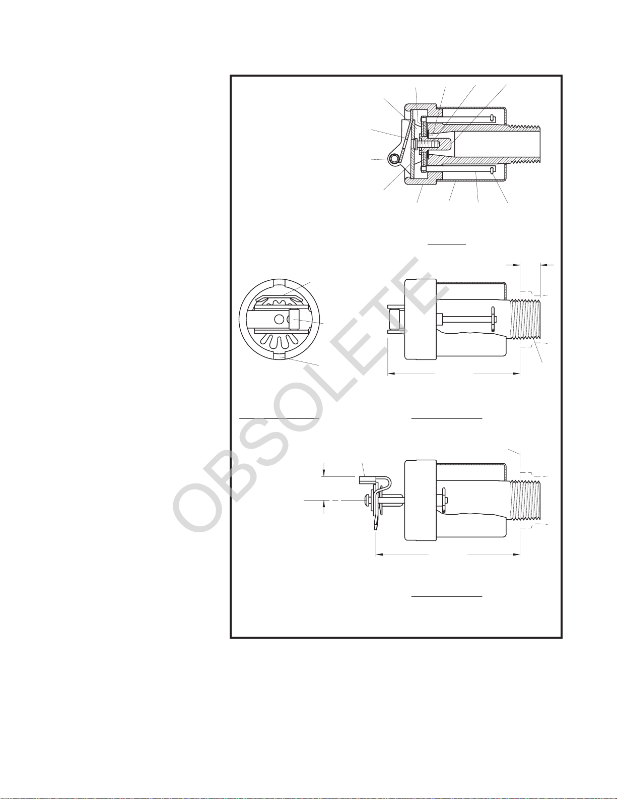
Step 1. The TFP PH5 Sprinklers must
be installed horizontally with the cen-
terline of their waterway perpendicular
to the back wall surface, and the De-
flector must be located with the top
towards the ceiling (Ref. Figure 1).
Step 2. With the Institutional Escutch-
eon in place and with pipe thread
sealant applied to the pipe threads,
hand tighten the sprinkler into the
sprinkler fitting.
Step 3. Wrench tighten the Sprinkler
using only the Model 1509-3 Sprin-
kler Wrench (Ref. Fig. 5). The wrench-
ing teeth of the Sprinkler Wrench are
to be applied to the sprinkler wrench-
ing notch areas (Ref. Fig. 1).
Step 4. After the installation is com-
plete, make certain that the Institu-
tional Escutcheon is held fast to the
mounting surface and that it sits
squarely against the wall around its
entire perimeter.
NOTE
The Sprinkler Body must not extend
beyond the Institutional Escutcheon
(Ref. Fig. 4). Otherwise the tamper
resistant design of the Model TFP PH5
will be compromised.
Care and
Maintenance
The 5.6 K-factor, Model TFP PH5
Sprinklers must be maintained and
serviced in accordance with the follow-
ing instructions:
NOTES
Service inspections should be made
on a regular basis to detect possible
damage or alterations to the sprinkler
and escutcheon. Inspections should
include making certain that the Institu-
tional Escutcheon is held fast to the
mounting surface. Damaged or altered
sprinklers are to be replaced immedi-
ately to avoid personal injury and to
prevent use for causing personal in-
jury, as well as to maintain the sprin-
kler system in an operative condition.
Before closing a fire protection system
main control valve for maintenance
work on the fire protection system that
it controls, permission to shut down the
affected fire protection systems must
be obtained from the proper authori-
ties and all personnel who may be
affected by this action must be notified.
Sprinklers that are found to be leaking
or exhibiting visible signs of corrosion
must be replaced.
Automatic sprinklers must never be
shipped or stored where their tempera-
tures will exceed 100°F/38°C and they
must never be painted, plated, coated,
or otherwise altered after leaving the
factory. Modified or over-heated sprin-
klers must be replaced.
Care must be exercised to avoid dam-
age to the sprinklers - before, during,
and after installation. Sprinklers dam-
aged by dropping, striking, wrench
twist/slippage, or the like, must be re-
placed.
The owner is responsible for the in-
spection, testing, and maintenance of
their fire protection system and de-
vices in compliance with this docu-
ment, as well as with the applicable
standards of the National Fire Protec-
tion Association (e.g., NFPA 25), in
TFP654 Page 3 of 4
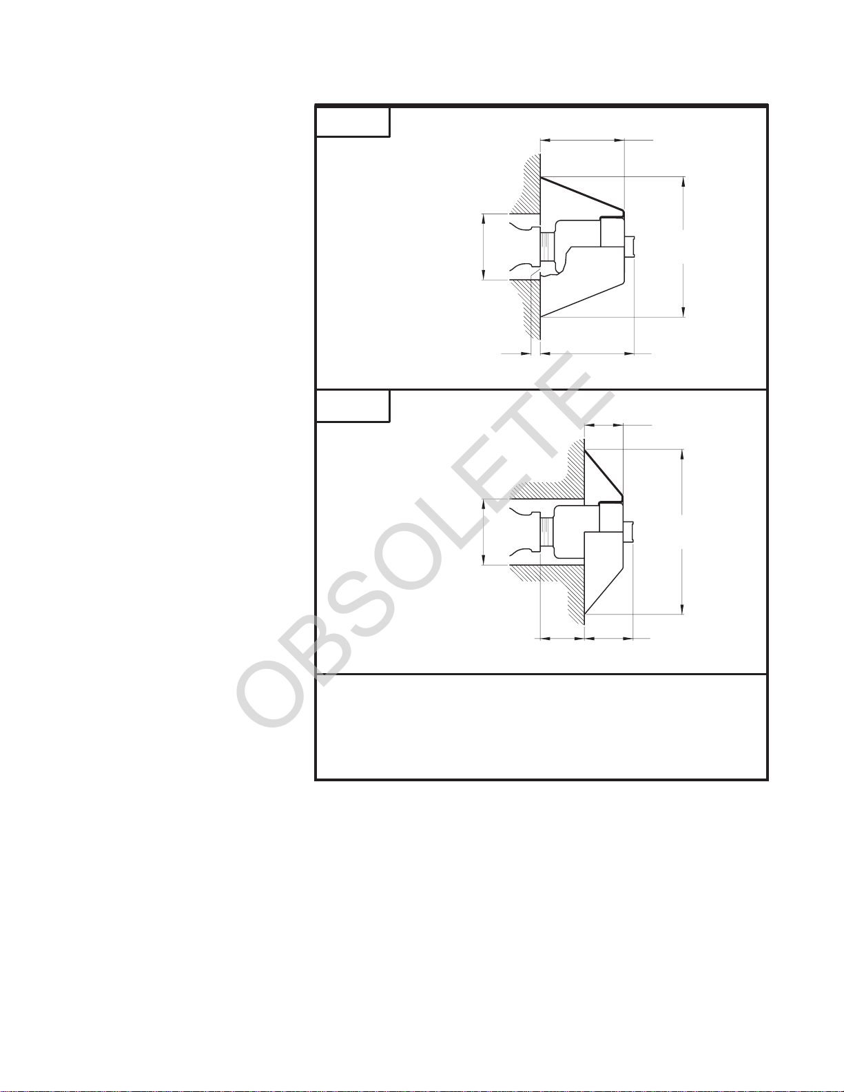
FIGURE 3
INSTITUTIONAL ESCUTCHEON OPTIONS
FOR USE WITH THE MODEL TFP PH5
NOTE: Model 1752 Spacers are not to be used to obtain horizontal adjustment for the
Model TFP PH5 with Style B2 or C Escutcheons.
CLEARANCE FOR
DETERMINED BY
DIAMETER
REDUCING
COUPLING
CLEARANCE FOR
DETERMINED BY
MOUNTING SURFACE
FITTING FLUSH WITH
FACE OF SPRINKLER
DIAMETER
REDUCING
COUPLING
(71.4 mm)
4-1/4" DIA.
(108.0 mm)
2.81"
(65.1 mm)
2-9/16"
1-3/16"
(30.2 mm)
5" DIA.
(127.0 mm)
(37.6 mm)
(33.8 mm)
1.33" 1.48"
STYLE B2
STYLE C