Ultra-Fab ULTRA 4002 Guide

ULTRA 4002 ELECTRIC TONGUE JACK
P/N 38-944016
US PATENT 9,821,774 B1
Rev 051519
INSTALLATION/OPERATION
APPLICATION
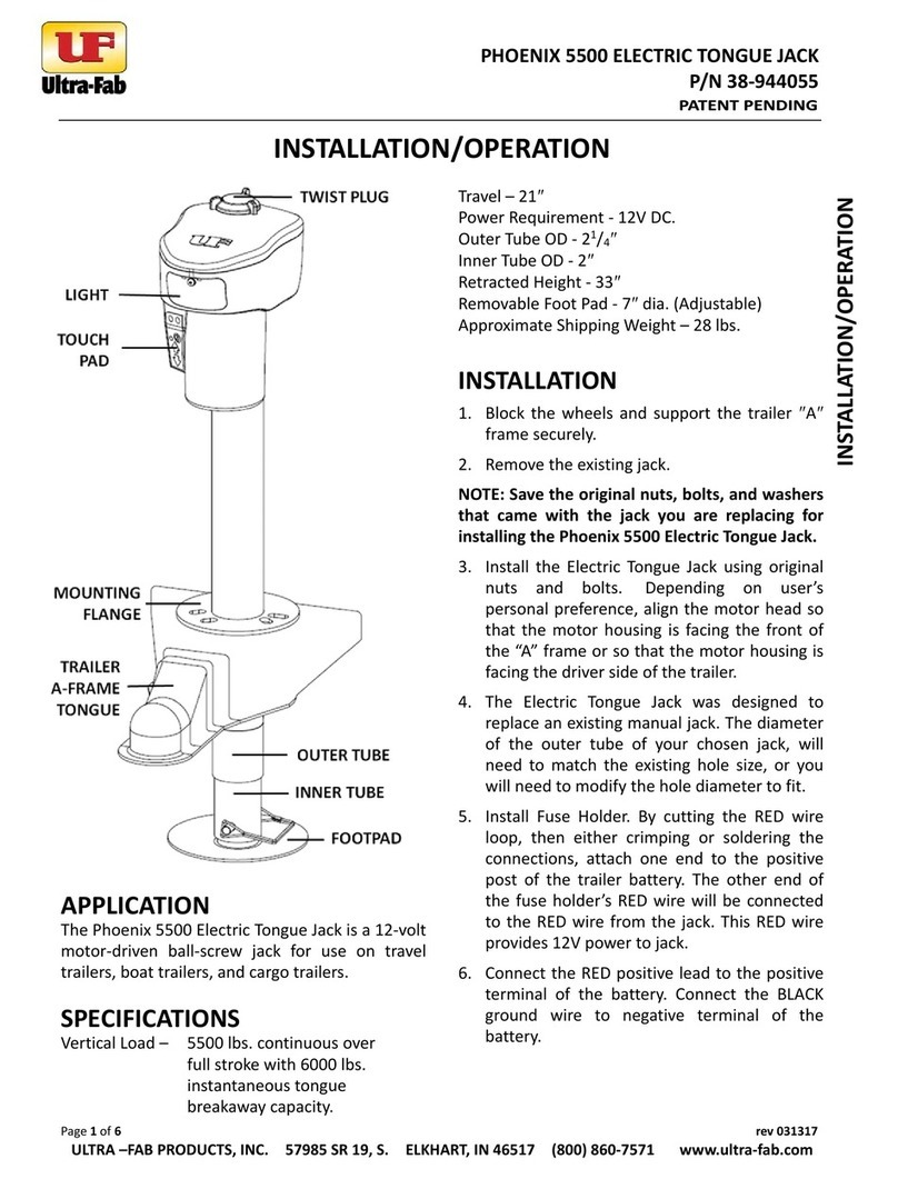
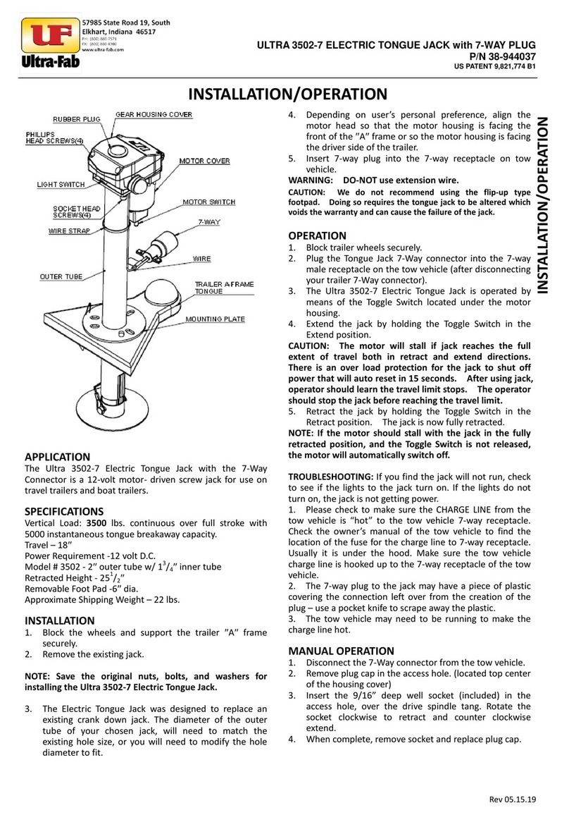
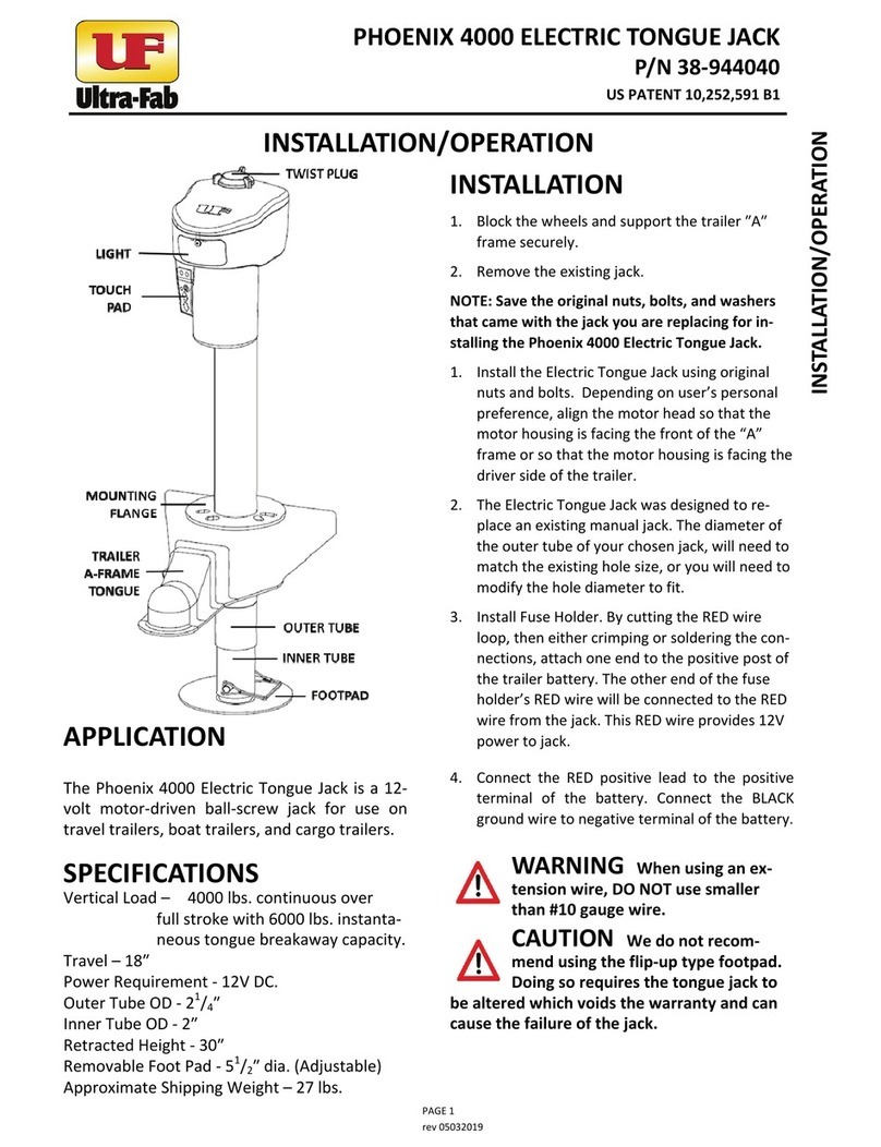
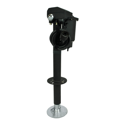
The Ultra 4002 Electric Tongue Jack is a 12-volt motor-driven
screw jack for use on travel trailers, boat trailers, and cargo
trailers.
SPECIFICATIONS
Vertical Load – 4000 lbs. continuous over full stroke with 6000
lbs. instantaneous tongue breakaway capacity.
Travel – 18″
Power Requirement - 12V DC.
Outer Tube - 2″
Inner Tube – 1¾″
Retracted Height - 251/2″
Removable Foot Pad - 51/2″dia. (Adjustable)
Approximate Shipping Weight – 22 lbs.
INSTALLATION
1. Block the wheels and support the trailer ″A″frame securely.
2. Remove the existing jack.
NOTE: Save the original nuts, bolts, and washers for installing
the Ultra 4002 Electric Tongue Jack.
3. Install the Electric Tongue Jack using original nuts and
bolts. Depending on user’s personal preference, align the
motor head so that the motor housing is facing the front of
the “A” frame or so that the motor housing is facing the
driver side of the trailer.
4. The Electric Tongue Jack was designed to replace an existing
manual jack. The diameter of the outer tube of your chosen
jack, will need to match the existing hole size, or you will
need to modify the hole diameter to fit.
5. Install Fuse Holder. By cutting the red wire loop, then either
crimping or soldering the connections, attach one end to the
positive post of the trailer battery. The other end of the fuse
holder’s red wire will be connected to the red wire from the
jack. This red wire provides 12V power to jack.
6. Connect the red positive lead to the positive terminal of the
battery. Connect the black ground wire to negative terminal
of the battery.
WARNING: When using an extension wire, DO-NOT use smaller
than #10 gauge wire.
CAUTION: We do not recommend using the flip-up type
footpad. Doing so requires the tongue jack to be altered
which voids the warranty and can cause the failure of the jack.
OPERATION
1. Block trailer wheels securely.
2. The Ultra 4002 Electric Tongue Jack is operated by means of
the Motor Switch located under the motor housing.
3. Extend the jack by holding the Motor Switch in the Extend
position.
CAUTION: The motor will stall if jack reaches the full extent of
travel both in retract and extend directions. There is an over
load protection for the jack to shut off power that will auto
reset in 15 seconds. After using jack, operator should learn the
travel limit stops. The operator should stop the jack before
reaching the travel limit.
4. Retract the jack by holding the Motor Switch in the Retract
position. The jack is now fully retracted.
NOTE: If the motor should stall with the jack in the fully
retracted position, and the Motor Switch is not released, the
motor will automatically switch off.
MANUAL OPERATION
1. Disconnect the fuse. (unscrew and pull apart)
2. Remove plug cap in the access hole. (located top center of
the housing cover)
3. Insert the 9/16″socket in the access hole, over the drive hex
head. Rotate the socket clockwise to retract and counter
clockwise to extend.
4. When complete, remove socket and replace plug cap, and
reassemble the fuse connection.
LUBRICATION
The jack is lubricated before leaving the factory. Under normal
conditions, lubrication will be needed after one year.
1. Grease the jackscrew by extending the jack until the grease
fitting is aligned with the hole in the outer tube. Using
standard chassis lube grease and a standard grease gun, give
two pumps.
2. Grease the gears in gearbox.
a. Remove the fuse from fuse holder.
b. Using a 6mm Allen Wrench, remove the four socket
head screws holding the motor/gear assembly to the
top of the outer tube. Lift this assembly up and off.
Unhook the wire connections in order to have enough
slack to remove.
c. To remove the top of the gear/assembly first, remove
the motor housing (4 screws). Two of the screws that
hold the gear cover are under the motor housing.
d. Remove the gear cover (4) screws and lube gears with
chassis lube.
e. Reassemble the gear/assembly.
f. Install the gear/assembly onto the lower stem, (it is
helpful to remove the rubber plug) and look through
the main gear in order to align the flats of the main
gear in the gear/assembly with the flats of the drive
collar of the lower stem. Turn collar to align flats if
necessary.
g. Install the 6mm bolts and hook up wire connections.
INSTALLATION/OPERATION

ULTRA 4002 ELECTRIC TONGUE JACK
P/N 38-944016
US PATENT 9,821,774 B1
Rev 051519
MOTOR/GEAR ASSEMBLY
No. Part No. Part Name Q'ty
1 38-752002 Gear Housing Cover 1
2 38-751154 Pinion Key 3x6 1
3 38-751152 Nut Nylon M5 2
4 38-751081 Washer 5mm Flat 2
5 38-752003 Main Gear Housing 1
6 38-751079
Lock Washer M4 8
7 38-751080 Spring Washer 4 8
8 38-751070 Screw - PPH M4x16 4
9 38-751010 Screw – PPH M4x12 4
10 38-752005 Motor Housing 1
11 38-751060 Screw - PPH M4x8 3
12 38-751142 Breaker – Circuit 12V 20A 1
13 38-752004 Light Housing 1
14 38-752006 LED Light 1
15 38-751140 Screw – ST2.9x6.5 2
16 38-752007 Light Lens 1
17 38-751174 Screw – ST4.2x13 2
18 38-751082 Grommet 1
19 38-751039 Switch Boot 1
20 38-751037 Motor Switch – on/off/on 250V 32A 1
21 38-751057 Light Switch – on/off 125/250V 6A 1
22 38-752008 Motor 150W 12VDC 1
23 38-751083
Rubber Plug 1
24 38-751118 Spur Gear 96T 1
25 38-751123 Washer Thrust 1
26 38-751124 Pinion Gear 12T 1
27 38-751085 Main Gear 89T 1
28 38-751114 Rubber Plug 1
29 38-751155 M8x25 Socket Head Cap Screw 4
30 38-751009 Lock Washer M8 4
31 38-114451 Lock Washer Internal Tooth M8 4
NOT SHOWN
Part No. Part Name Q'ty
38-751167 Socket 9/16” Deep Well / Manual
Override 1
38-751034 250V 30A Slow-Blow Fuse 1
38-751035 Fuse Holder 1

ULTRA 4002 ELECTRIC TONGUE JACK
P/N 38-944016
US PATENT 9,821,774 B1
Rev 051519
LOWER STEM ASSEMBLY
38-751170 Lower Stem Assembly (Includes #1 & #2)
No. Part No. Description Q'TY
1 38-751102 2" Outer Tube 1
2(A-G) 38-751160 1.75" Inner Tube Assembly 1
2A 38-752018 Retaining Pin 5mm 1
2B 38-752019 Washer Spacer AS1730 1
2C 38-751138 Cotter Pin 1
2D 38-751127 Upper Pin 1
2E 38-751122 Collar Hex Head 1
2F 38-751121 Thrust Bearing 1
2G 17-753230 Grease Zerk 6-1.0mm 1
3 38-752020 Footpad Adjustable 2” (U4002) 1
4 38-141023 Wire Lock Pin 1

ULTRA 4002 ELECTRIC TONGUE JACK
P/N 38-944016
US PATENT 9,821,774 B1
Rev 051519
WIRING DIAGRAM

ULTRA 4002 ELECTRIC TONGUE JACK
P/N 38-944016
US PATENT 9,821,774 B1
Rev 051519
T
TW
WO
O-
-Y
YE
EA
AR
R
L
LI
IM
MI
IT
TE
ED
D
W
WA
AR
RR
RA
AN
NT
TY
Y
ULTRA 3502/3502-7/4000/4002 TONGUE JACKS
THE MANUFACTURER NAMED BELOW MAKES THE FOLLOWING
WARRANTY WITH RESPECT TO THE ABOVE ULTRA-FAB PRODUCTS
1. This Warranty is made only to the first Purchaser (hereinafter called the “Original Purchaser”) who acquires this product for their own use.
2. This Warranty will be in effect for two years from the date of purchase by the Original Purchaser. It is suggested that the Original Purchaser retain a
copy of the dated bill of sale as proof of the date of purchase.
3. This Warranty covers only specified parts which shall be free from defects in material and workmanship under normal use. This Warranty does not
cover conditions unrelated to the material and workmanship of the product. Such unrelated conditions include, but are not limited to (a) faulty
installation and any damage resulting from such; (b) the need for normal maintenance and any damage resulting from the failure to provide such
maintenance; (c) failure to follow Manufacturer’s instructions for use of this product, and (d) any accident to, or misuse of, any part of this product
and any alteration by anyone other than the Manufacturer or its authorized representative.
4. In order to obtain the benefits of this Warranty, you should return the product which you find defective to the Manufacturer named below during the
period that this Warranty is in effect. All charges incurred in delivery of the product to the Manufacturer, and in picking it up after the Warranty
service has been completed, must be paid by the Original Purchaser.
5. Any item returned in the manner described in paragraph 4 will be examined by the Manufacturer. If it is found that the returned item was defective
in material or workmanship, the Manufacturer will repair it without charge for material and labor.
6. Ultra-Fab will pay freight on replacement parts during the first 90 days of ownership by the Original Purchaser.
7. The Manufacturer does not authorize any person or company to create any Warranty obligation or liability on their behalf.
8. IN NO EVENT SHALL THE MANUFACTURER BE LIABLE FOR INCIDENTAL OR CONSEQUENTIAL DAMAGES. SOME STATES DO NOT ALLOW THE
EXCLUSION OR LIMITATION OF INCIDENTAL OR CONSEQUENTIAL DAMAGES SO THE ABOVE LIMITATION OR EXCLUSION MAY NOT APPLY TO YOU.
9. ANY IMPLIED WARRANTY, INCLUDING THE IMPLIED WARRANTY OF MERCHANTABILITY AND FITNESS FOR ANY PURPOSE, IS LIMITED TO THE
DURATION OF THIS LIMITED WARRANTY. SOME STATES DO NOT ALLOW LIMITATIONS ON HOW LONG AN IMPLIED WARRANTY LASTS, SO THE
ABOVE LIMITATION MAY NOT APPLY TO YOU.
10. THIS WARRANTY GIVES YOU SPECIFIC LEGAL RIGHTS, AND YOU MAY ALSO HAVE OTHER RIGHTS WHICH VARY FR0M STATE TO STATE.
57985 SR 19 S., Elkhart, IN 46517
Tel: (574) 294-7571 Fax: (574) 294-4980
www.ultra-fab.com
This manual suits for next models
2
Table of contents
Other Ultra-Fab Jack manuals
Popular Jack manuals by other brands

Cattini
Cattini YAK 215/L Operating and maintenance manual

Clarke
Clarke CTJ1250AC Operation & maintenance instructions

Würth
Würth 0715 54 311 operating instructions

Cattini
Cattini YAK 215/N Operating and maintenance manual

Tronair
Tronair 02-0511C0132 Operation & service manual

Tronair
Tronair 02-1036C0111 Operation & service manual