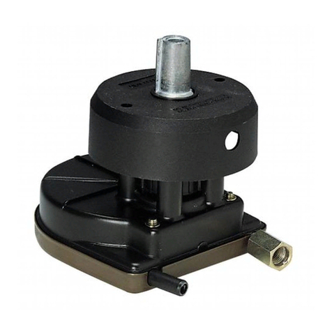
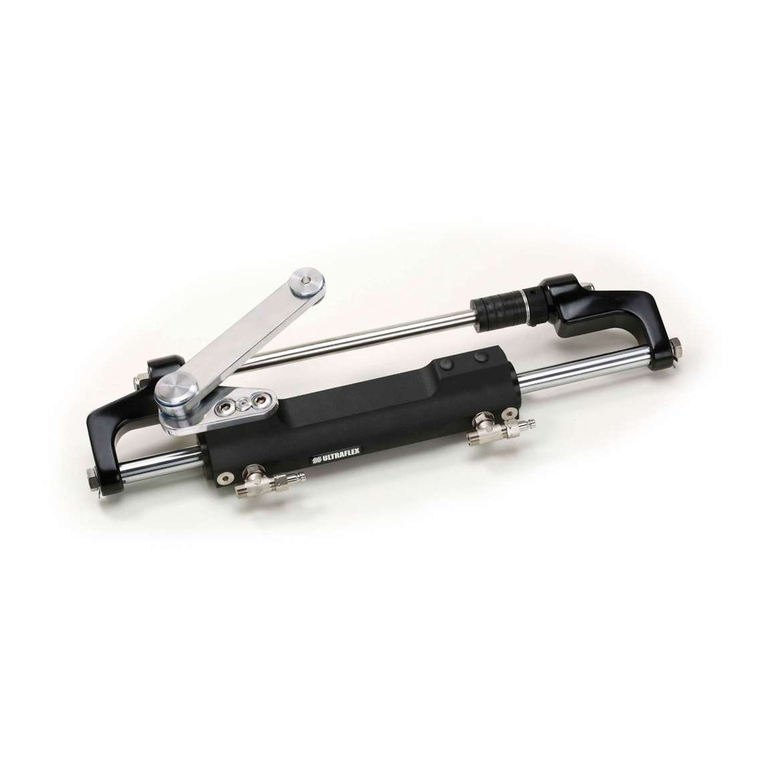
Ultraflex UC 68-OBS Manual

HYDRAULICCYLINDERSFOR
SIDEMOUNT APPLICATIONS
InstallationandMaintenanceManual
UC133-IOB
UC68-OBS
UC132-OBS
(Dr.No.23068/e16/07/2019)
PARTNER

ITALIANO
UFLEXUSA
Sarasota,FL34243 -6442 ParklandDrive
"Establishedin1989 UFLEX USAis aleaderinsteeringandcontrolsystemsforthemarineindustry.
Withfull manufacturingcapabilities inSarasota, Florida, UFLEX USAcansupportall sectorsofthemarine
industryregardless ofvolumeand/orproductrequirements. And,asanaffiliateofthe ULTRAFLEX Group,
UFLEX USAhas tremendousresources todrawuponfornewproductdevelopmentinhydraulics, electronics
andmanyothertechnologies.
Innovative productdesignandunparalleleddedicationtoqualitycustomerservice andproductsconti-
nuetobecornerstoneof UFLEX USA's growth.Todayourproductscanbefoundas originally installed
equipmentonmanyofthemostwidelyknownandrespectedboatbrandsintheworld.
Aftermarketpartscanbesourcedfromtrainedandexperienceddistributornetwork throughoutNorth
andSouthAmerica.
Ourdedicationtoprovidingthehighestqualityproductsandservice is onlymatchedbyourcommitment
todevelopingnewproductsemployingthelatestmaterialsandtechnology toenhance ourcustomer's
boatingexperience. Fromsteeringwheelstosophisticatedelectronic controls, UFLEX USAhas everything
youneedtomakesurethatyourboatlooksandperformit's bestformany,manyyears."
DearCustomer,
Wewould liketothankyouforchoosingan ULTRAFLEX SpAproduct.
ULTRAFLEX SpAhasbeenaleaderinsteeringsystemsforpleasureandprofessionalboatsformany
years.
All ULTRAFLEX SpAproductsaredesignedandmanufacturedtoensurethebestperformance.
To ensureyoursafetyandtomaintainahighqualitylevel, ULTRAFLEX SpAproductsareguaranteedonly
iftheyareusedwithoriginalspareparts(see attacheddocument"ApplicationSpareParts").
Thequalitymanagementsysteminvolvesallthecompanyresourcesandprocesses startingfromthe
design,inorderto:
- ensureproductqualitytothecustomer;
-maintainandimprove thequalitystandardsconstantly;
-pursueacontinuousprocess improvementtomeetthemarketneedsandtoincrease thecustomer
satisfaction;
-constantlytesttheproductstoverifytheirconformitywiththe2013/53/EU.

HYDRAULIC CYLINDERFORSIDEMOUNTAPPLICATIONS -page 3 of 23
InstallationandMaintenanceManual
SECTION1-PRODUCTDESCRIPTION
1.1 HYDRAULICSTEERINGSYSTEMOPERATION..................................................................................6
1.2 WARNINGSFORTHECORRECT PRODUCTUSE..................................................................................6
1.3 CONFIGURATIONS........................................................................................................................7
1.4 CYLINDERDESCRIPTION..............................................................................................................................8
1.5 TECHNICALFEATURES................................................................................................................................8
TABLEOFCONTENTS
SECTION2-TRANSPORT
2.1 GENERALWARNINGS.............................................................................................................................9
2.2 PACKAGINGCONTENTS.................................................................................................................9
SECTION5-MAINTENANCE
5.1 ORDINARY MAINTENANCE.................................................................................................................20
5.2 TROUBLESHOOTING........................................................................................................................19
SECTION3-INSTALLATION
3.1 DIMENSIONS...............................................................................................10
3.2 NECESSARY TOOLS..................................................................................................................10
3,3 CYLINDERINSTALLATION............................................................................................................11
3,4 HOSEINSTALLATION...................................................................................................................12
3.5 TYPEOFINSTALLATION.............................................................................................................................12
3.6 FILLINGANDPURGING.......................................................................................................................14
3.6.1POSITIONINGOFTHEOILBOTTLE..........................................................................................14
3,6,2SINGLE STEERINGSTATION/SINGLE CYLINDER.......................................................................................17
3.6.3SINGLE STEERINGSTATION/DUAL CYLINDER..............................................................................18
3.6.4DUALSTEERINGSTATION/SINGLECYLINDER.........................................................................................18
3.6.5DUALSTEERINGSTATION/DUALCYLINDER..............................................................................................17
3.7 GENERALRECOMMENDATIONS.........................................................................................................17
SECTION4-SAFETYWARNINGS
4.1 SAFETYWARNINGSDURINGUSEAND INSTALLATION........................................................................19
4..2 CLOTHING.................................................................................................18
SECTION6-DISMALTING
6.1 DISMALTING.......................................................................................................................21
!
MANUALUSEANDSYMBOLSUSED................................................................................................................4
INTRODUCTION.................................................................................................................................5
WARRANTY.............................................................................................5
IMPORTANT:
Theadditionaldocuments"ApplicationGuide"and"SparePartsList" areattachedtothismanual.

InstallationandMaintenanceManual
page 4 of 23-HYDRAULIC CYLINDERFORSIDEMOUNTAPPLICATIONS
STERN
BOW
STARBOARD PORT
THEINSTALLATION AND MAINTENANCE MANUAL is thedocumentaccompanyingtheproductfromitssale
toitsreplacementanddischarge.Themanualis animportantpartoftheproductitself.
It is necessarytoreadcarefully themanual,beforeANY ACTIVITYinvolvingtheproduct,handlingand
unloadingincluded.
Thepictureasideexplainsthemeaningofsome
nauticalwordscontainedinthismanual.
MANUALUSE AND SYMBOLSUSED
DANGER ImmediatehazardswhichCAUSEseverepersonalinjuryordeath.
WARNING
CAUTION
Thesymbolasideindicates all theoperationswhichmustbecarriedout
byqualifiedorskilledstaff,inordertoavoidhazards.
Werecommendtrainingthestaffinchargeoftheproductinstallation
andcheckingtheirknowledge.
NOTICE Importantinformationforthecorrectinstallationandformaintenance,that
doesnotcauseanydamage.
Denotes thatahazard existswhichcanresult ininjuryordeathifproper
precautionsarenottaken.
Denotesareminderofsafetypracticesordirectsattentiontounsafe
practices whichcould result inpersonalinjuryordamagetothecraft or
componentsortotheenvironment.
LEGEND
m.p.h. =miles perhour
km/h=kilometres per
hour
10 m.p.h. =8,69 knots
10 m.p.h. =16,1 km/h
10 knots =11,5 m.p.h.
10 knots =18,5 km/h
10 km/h=6,21 m.p.h.
10 km/h=5,4 knots
er

HYDRAULIC CYLINDERFORSIDEMOUNTAPPLICATIONS -page 5 of 23
InstallationandMaintenanceManual
INTRODUCTION
This installationandmaintenance manualrepresentsanimportantpartoftheproductandmustbeavailable
tothepeopleinchargeofitsuse andmaintenance.
Theusermustknowthecontentofthis manual.
UFLEX USAdeclinesallresponsibilityforpossiblemistakesinthis manualduetoprintingerrors.
Apartfromtheessentialfeaturesofthedescribedproduct, UFLEX USAreservestherighttomakethose
modifications, suchas descriptions, detailsandillustrations, thatareconsideredtobesuitableforits
improvement,orfordesignorsales requirements, atanymomentandwithoutbeingobligedtoupdatethis
publication.
ALLRIGHTSARE RESERVED.Publishingrights,trademarks,partnumbersandphotographsof UFLEX USA
productscontainedinthismanualare UFLEX USAproperty.
Greatcarehas beentakenincollectingandcheckingthedocumentationcontainedinthismanualto
makeitas completeandcomprehensibleaspossible. Nothingcontainedinthis manualcanbeinterpreted
as warrantyeitherexpressedorimplied-including,notinarestrictedway,thesuitabilitywarrantyforany
specialpurpose.Nothingcontainedinthismanualcanbeinterpretedasamodificationorconfirmationof
thetermsofanypurchasecontract.
TECHNICALASSISTANCE SERVICE
UFLEX S.r.l.
ViaMiliteIgnoto,8A
16012 Busalla(GE)-Italy
Tel:+39.010.962.0239(Italy)
Tel:+39.010.962.0244 (abroad)
Fax: +39.010.962.0333
Email: ut@uflexgroup.it
www.uflexgroup.it
North-South-CentralAmerica:
UFLEX USA
6442ParklandDrive
Sarasota,FL34243
Tel:+1.941.351.2628
Fax: +1.941.360.9171
Email: uflex@uflexusa.com
www.uflexusa.com
Toensurethecorrectproductandcomponentoperation,theproductmustbeinstalledbyqualifiedstaff.
Incaseofpartdamageormalfunction,please contactthequalifiedstafforourTechnicalAssistance
Service.
WARNING
WARRANTY
1. TwoYearLimitedWarranty. UFLEX USA, Inc.warrantsthatall productsmanufacturedby UFLEX USA,
Inc. or ULTRAFLEX S.p.A. andsold by UFLEX USAtotheretailpurchaser("Purchaser")thatfortwo(2)years
afterthedateofmanufacturetobefreefromdefectsduetomaterialorworkmanship,subjecttothe
exclusionsbelow.ImproperinstallationVOIDSthiswarranty.Installationshouldonlybeattemptedbya
trainedandqualifiedtechnician.
2. Exclusions. This limitedwarrantydoes notcover anddoes notextendtoanyofthefollowing:
(a) Failurecausedbynormalwearandtear,climatic conditions, misuse, neglect,lackofpropermaintenance,
accident,fireorothercasualtydamage, racing,overloading,negligence,modification,beachingor
groundingofvessel,collision,impact,towing,actsofwarorhostilities;
(b) componentsnotmanufacturedby UFLEX USA,Inc.,oritsaffiliates;
(c) costofremovalorreinstallationofanycomponent(includingcomponentsmanufacturedby UFLEX USA,
Inc.)ordisassembly orreassembly oftheunitcontainingthecomponent;
(d) componentsnotmanufacturedby UFLEX USA, Inc. or ULTRAFLEX S.p.A., whetherornotwarrantedbythe
othermanufacturer;
(e) anyproductwhichhasnotbeenproperlyinstalled.

InstallationandMaintenanceManual
page 6 of 23-HYDRAULIC CYLINDERFORSIDEMOUNTAPPLICATIONS
3. Limitations. THEREPAIROR REPLACEMENT OFDEFECTIVE PARTSSHALL BE PURCHASER'SSOLE AND
EXCLUSIVE REMEDYAND UFLEX USA, INC,'SSOLE AND EXCLUSIVE LIABILITY UNDER THISWARRANTY.
LABOR FOR REPLACEMENT IS NOT INCLUDED. UFLEX USA, Inc.'s obligationunderthis warrantyis limited
totherepairorreplacement(at UFLEX USA, Inc.'s soleelection)ofanycovereditemfoundtobedefective,
whendeliveredbyPurchaserpursuanttowrittenauthorizationandinstructionsfrom UFLEX USA,Inc.,
shippingprepaidto UFLEX USA,Inc.'splantorotherdesignatedrepairfacility.Repairedorreplaced
itemsarewarrantedasprovidedhereinfortheunexpiredportionoftheapplicablewarrantyperiod.
THISWARRANTY, AND THERIGHTSAND REMEDIESUNDER IT, IS EXCLUSIVE AND IS GIVEN INPLACE OF
ALL OTHER WARRANTIES,WHETHER EXPRESS OR IMPLIED, INCLUDING ANY IMPLIED WARRANTY OF
MERCHANTABILITY OR FITNESS FOR PARTICULAR PURPOSE, WHETHER ARISING BY LAW,CUSTOM,
CONDUCT OR USAGE OFTRADE, PURCHASER'SREMEDIESSHALL BE LIMITED ASSTATED HEREINAND
UFLEX USA, INC. SHALL NOT BE LIABLE FOR ANY INCIDENTAL, CONSEQUENTIAL OR INDIRECT DAMAGES
OR LOSSESRESULTING FROMDEFECTS.THERETAILSELLER IS NOT ACO-WARRANTOR AND IS NOT
AUTHORIZED BY UFLEX USA, INC. TO AMEND OR MODIFYTHISLIMITED WARRANTY INANY MANNER.
4.TransferabilityofWarranty. Thislimitedwarrantymay notbetransferredtosubsequentpurchasers.
5. Miscellaneous. UFLEX USA, Inc.is anaffiliateof ULTRAFLEX S.p.A. UFLEX,USA, Inc., reserves therightto
makechanges inthedesignandconstructionofitsproductsatanytime, withoutnotice andwithoutany
obligationtoincorporatesuchchanges intoproductsofpriormanufacture. Thislimitedwarrantyapplies
tonewcomponentssold by UFLEX USA, Inc.. This limitedwarrantycontainstheentireagreementsbetween
UFLEX USA, Inc.andPurchaserandsupersedesallprioragreements,discussions, negotiations,
commitmentsandrepresentations, whetheroralorwritten,betweenthemregarding UFLEX USA, Inc's
warranty.If anyprovisionofthislimitedwarranty, ortheapplicationofit,isdeterminedtobeinvalidof
unenforceableforanyreason,theremainderofthislimitedwarrantyandtheapplicationofitshallnot
beaffected.
All communicationsandnoticesfromPurchaserregardingthis limitedwarrantyshould besentto: UFLEX
USA, INC., 6442 ParklandDrive, Sarasota, FL34243; (941)351-2628.
Return policy
Anyproductthatis presumeddefective shouldbereportedto UFLEX USAwithin48 hoursofreceiptor
discoveryinthefield.Uponnotification UFLEX USAwill attempttotroubleshoottheproblemwithourcustomer
overthephone.If weareunabletoresolvetheproblem UFLEX willissueaReturnGoodsAuthorization
numberandwerequirethattheproductinquestionbereturnedto UFLEX withallitspartsinitsoriginal
packaging.Theproductshouldbereturnedfreightprepaidto:
UFLEXUSA
RGA Department-RGA #
6442ParklandDrive
Sarasota, Florida34243
Uponreceipt UFLEX will examinetheproducttodeterminethecause ofthedefect.If theproductis determined
tohaveadefectinworkmanshipormaterial,itwillberepairedatourdiscretion.
Ourwarrantydoes notcoverlabor,towingorotherexpenses. Further,itdoes notcoverproductsthathave
beenimproperly installed,damagedininstallation,misapplied,ormisused.
Ourproductsarenotintendedforuseinracingapplications.

HYDRAULIC CYLINDERFORSIDEMOUNTAPPLICATIONS -page 7 of 23
InstallationandMaintenanceManual
TheUC 68-OBS,UC 132-OBSandUC 133-IOB sidemountcylindersmustnotbeinstalledonrace boats.
Dualengineapplicationsrequiretwosteeringcylindersandtie bar,whenthecombinedenginehorsepower
exceeds450hp,and/orwhentheboatspeedexceeds55 m.p.h.
All ULTRAFLEX steeringsystemsmustnotbeinstalledonboatsequippedwithengines whosemaximum
horsepoweris higherthanthehorsepowerratingapprovedby boatmanufacturer.
1.2 Warningsfortheproductcorrectuse
Beforebeginningtheinstallation,checkthemountingcompatibilityoftheUC 68-OBS,UC 132-OBSandUC
133-IOB cylinderstotheenginebyconsultingtheattacheddocument"ApplicationGuide"containedinthe
packaging.
WARNING
WARNING
WARNING
WARNING
DANGER
1PRODUCTDESCRIPTION
1.1Hydraulicsteeringsystemoperation
l
engine
l
hydraulic
hose
l
cylinder
l
pump
All UFLEX hydraulicsteeringsystemsaredesignedinconformitywithUNI-EN-ISO10592andA.B.Y.C.P21
regulations. All UFLEXsteeringsystemscanoperateattemperatures between-18°C(0°F)and+77°C(+170°F).
Allthecomponentsaremadeforthemarineenvironment,usingmaterialsandworkingprocesseswhich
offerlonglifeandsafetyunderthemostextremeconditions. Ahydraulicsteeringsystemconsistsofa
steeringpump,acylindertiedtotherudderortotheoutboard or
sterndrive engineandtheconnectinghoses (see picture).Under
normaloperatingconditions, aturnofthesteeringwheelwill pump
theoil,whichflowsinthroughthehoses tothecylinder,according
totheturndirection.Withtheconsequentcylindermovementthe
oilwillflowtothepumpthroughthehoses andatthesametime
moves theengineorthehelmwhichareconnectedtothecylinder.
Thepumpsareequippedwithavalve,whichpreventsoutgoing
fluidfromreturningalongthe samehose. It also allows the operation
ofthesteeringsystemswithtwoormoresteeringstations. The
cylindersaredoubleactingandmaybebalancedorunbalanced.
Intheunbalancedcylindersthetwochambershavedifferent
volumes andso they needadifferentnumberofturnsofthesteering
wheelandadifferentrotationeffort.Thebalanced cylindershave
samenumberofsteeringwheelturnsinordertomove thehelmfromthecentertotheendstrokeinthetwo
oppositedirections. Awellbalancedsteeringsystemneedsacorrectchoice ofthepumpforthecylinder.
UFLEX produces differentpumpmodels,whichhave differentcapacity(cm3ofoilmovedeachsteeringwheel
turn)andforeachtypeofinstallation.Whilechoosingthepumpitisimportanttoconsiderthecylinder
volume. Thenumberofstarboard andportturnsis determinedby theratiobetweenthecylindervolume
andthepumpcapacity.
Example:ifthepumphas acapacityof28 cm3 [1,7cu.in.]andthecylinderhas avolumeof132cm3 [7,3cu.in.],the
formulalookslikethis: 132/28=4,7.Accordingly, thesteeringwheelwill turn4times andanhalf beforethe
cylinderwill completelyturnfromonesidetotheother.Incaseofinstallationswithdoublecylinders
connectedinparallelthecylindervolumemustbeadded.Applicationswithlessthan4turnsarenot
recommended,astheyneedahighereffort,alsoapplicationswithmorethan8turnsarealsonot
recommended,astheresponse oftheboattosteerisslowly.Themaximumoperatingpressureis7,0MPa
(70bar)(1000 PSI).
Do notmodifythesteeringcylinderinanyway tofitittoyourengineapplication,otherwise thecylinderwill
nolongeroperateinsafetyanditwillendangertheboatandtheoccupants.

InstallationandMaintenanceManual
page 8 of 23-HYDRAULIC CYLINDERFORSIDEMOUNTAPPLICATIONS
1.3Configurations
ThehydrauliccylindersforsidemountinstallationsUC68-OBS,UC132-OBS,UC133-IOBmodelcanbe
installedwithdifferentconfigurationsaccordingtothenumberandthetypeofengines usedwithasingleor
dualenginesteeringsystem.
Thepossibleconfigurationsare:
S
I
N
G
L
E
S
T
A
T
I
O
N
ENGINE NUMBER
With
SINGLECYLINDER
With
SINGLECYLINDER
and
TIEBAR
With
DUALCYLINDER
and
TIEBAR
up to250hpmax
andupto55 m.p.h.
MAIN
STATION
ADDITIONAL
STATION
D
U
A
L
S
T
A
T
I
O
N
S
I
N
G
L
E
E
N
G
I
N
E
D
U
A
L
E
N
G
I
N
E
DANGER
Dualengineinstallationsrequiretheuse ofatiebar.
upto150hpmaxandup
to55m.p.h.
UC 68-OBS UC 132-OBSUC 133-IOB
counterandnon-counterrotatingengines
upto300hpmaxof combinedhorsepower
andupto60 m.p.h.
non-counterrotatingenginesupto
250hpmax ofcombined horsepowerandup
to55m.p.h.;
counterrotatingenginesupto300hpmax
ofcombinedhorsepowerandupto
55m.p.h.
enginesupto150hpmaxofcombined
horsepower and up to
55m.p.h.
With
SINGLECYLINDER
STEERINGSTATION
NUMBER
With
SINGLECYLINDER
and
TIEBAR
NOTICE
Thepictures above areindicati-
ve,forfurtherinformationabout
installationseeparagraph3.5,
NOTICE
Incase ofusewithpower-assistedsterndrives,please contactourTechnicalAssistance Service.

HYDRAULIC CYLINDERFORSIDEMOUNTAPPLICATIONS -page 9 of 23
InstallationandMaintenanceManual
1.4Cylinderdescription
UC 68-OBS,UC 132-OBSandUC133-IOB arehydraulic sidemountcylinderswhichhave beendesignedand
manufacturedtobeusedasacomponentinthehydraulicsteeringsystems, asdescribedintheprevious
paragraph.
Thecylindersareinstalledontherightsideofthetilt tubeoftheavailableoutboard engines onthemarket,
and,accordingtothesameinstructionsdescribedinthis manual,they arealso installedonthetilt tubes of
theinboard-outboard applications. It is possibletoadjustthecylindertoall thedifferentengineapplications
thankstoalinkarmsuppliedwiththeengine. Thefollowingpictures showthemaincylindercomponents:
Cylinderbody
Bleeders
Pin
Extension
1
2
3
4
1.5Technicalfeatures
SPECIFICATIONS UC68-OBS UC132-OBS UC133-IOB
Volume 68/100cc-4.1/6.1cu.in 132/163cc-8/9.95cu.in 132cc-8cu.in
Outoutforce 185/270kg-408/595Ibs 455/563 kg-1003/1240lbs 455kg-1003lbs
Insidediameter 25mm -0.98" 32mm-1.25" 32 mm-1.25"
Stroke 203mm -8" 203mm-8" 203mm-8"
Oil incompliancewithISOVG15incompliancewithISOVG15incompliancewithISOVG15
UC68-OBS(unbalanced)
2
3
4
UC133-IOB (balanced)
UC132-OBS(unbalanced)
1
1
1
2
2
3
3
4
4
WARNING
Theunbalancedcylinderscanbeusedonlywith ULTRAFLEX pumps.
OIL15 OIL15 OIL15

InstallationandMaintenanceManual
page 10 of 23-HYDRAULIC CYLINDERFORSIDEMOUNTAPPLICATIONS
CONTENTSOFTHESTANDARDPACKAGING:
A)No.1cylinderbody:
B)No.1extention;
C)pin;
D)No.1plastichoseforthehydrauliccircuitbleeding;
2.1 Generalwarnings
2TRANSPORT
Theproductweightwithitspackagingis 3kg (7pounds)andso itcanbehandledmanually.
2.2 Packagingcontents
Beforeusingtheequipmentcheckthattheproducthasnotbeendamagedduringtransport.
Alsomakesurethatallthestandardcomponentsareinthepackaging(seelist).Incaseofdamage,
notifytheclaimtotheforwarderandinformthesupplier.
WARNING
Thestaffinchargeofhandlingmustoperatewithprotectivegloves andsafetyshoes.
UC132-OBS
UC68-OBS
UC133-IOB
ll
l
B
A
l
D
l
A
A
l
l
D
l
l
B
l
l
B
D
l
CC
C
Thepackagingmustbedisposedofaccordingto theexistinglaws.
CAUTION

HYDRAULIC CYLINDERFORSIDEMOUNTAPPLICATIONS -page 11 of 23
InstallationandMaintenanceManual
3INSTALLATION
3.1Dimensions
Thefollowingpictures showthedimensionsofthevariousmodels.Beforetheinstallationconsiderthe
dimensionsinordertoavoiddamagestothecylinderandtotheboat.
3.2Necessary tools
Openend
wrench
32mm [11/4”]
Torquewrench
UC68-OBS
UC132-OBS
UC133-IOB
329,3 mm -12.96"
340 mm -13.3"
340 mm -13.3"
340 mm -13.3"
337 mm -13.27"
332 mm -13.1"
Openend
wrench
16mm [5/8”]
Duringinstallationuse onlystainless steeltoolstopreventthecorrosionofthemetalparts.
CAUTION

InstallationandMaintenanceManual
page 12 of 23-HYDRAULIC CYLINDERFORSIDEMOUNTAPPLICATIONS
3.3 Cylinderinstallation
1Carryoutthe
standard installation
ontherightsideof
theengine(see notice
par.3.5).
Greasetheextention
(1)andtherod(2),by
usingmarinegrease
topreventthe
corrosionofthemetal
parts.
3Insertthecylinderrod(2)intheextention(1)
bylockingitbymeansofthepin(3),thenholding
thepinwithyourhandcontinuetoinsertthetilt
tuberodintothetilt tube.
Theenginemuststopthroughthecylinderendstroke
withoutcomingintocontactwiththemechanicalstop(5)
ontheengine.
NOTICE
4Screwthelockcollar(4)tothethreadedpart
ofthetilttubeandtightenitwithatorqueof40
[Nm](29.5[lb·ft]).
l
4
6Checkthecorrectcylinderinstallationbymovingmanuallytheengineontherightandontheleft.
WARNING
Whentheengineincentralposition,thecylinder
rodmustbeinthemiddleofitsstroke.
Ifitis necessaryadjusttheball jointonthelink
armaccordingtotheenginemanufacturer's
instructions.
3
l
2
l
2Insertthefirstpartoftheextension(1)intothe
tilttube.
1
l
1
l
NO CONTACT
l
5
5 Connectthelinkarm(suppliedby theengine
manufacturer)totheextentionaccordingtothe
enginemanufacturer's instructions, thenconnectit
tothearm,makingreferencetothedatasupplied
bytheenginemanufacturer's instructions.
Thelinkarmis suppliedwuththeengineandfor
itsinstallationfollowthemanufacturer's
instructions.
WARNING

HYDRAULIC CYLINDERFORSIDEMOUNTAPPLICATIONS -page 13 of 23
InstallationandMaintenanceManual
3.4Hoseinstallation
DANGER
NO
WARNING
Anexcessivehosebendcould result initsinternalbreakingwhich
will cause abadoperationofthesystem.Inthis case itis necessaryto
replace thedamagedhose.
ThefittingsmountedonthecylinderCANNOTbeorientated.
Ifthey areunscrewed,they will bedamagedandso thecylindercannot
beused.
3.5Typeofinstallation
NOTICE
Accordingtothestandardsinforcetheremustbea7/8"-14UNFthreadonly ontherightsidewithaminimun
lengthof16mm (0.62")ofthetilttube,checkthesedimensionsbeforethecylinderinstallation.
Incase ofinstallationoftheleft sideordualinstallation,checkthateventhethreadis locatedontheleft side
andthatitsfeaturescorrespondtotheonesdescribedinthestandards.
Do not install thecylinderinthisconfiguration,ifthereis nothreadorincaseofnon-compliancewiththe
standards.
Thehydraulic cylindersUC 68-OBS,UC 132-OBSandUC 133-IOB forsidemountapplicationscanbeinstalled
withdifferentconfigurationsaccordingtothenumberandthetype ofengines usedwithasingleordual
steeringsystem.
CAUTION
Connecthosesas shown inthepicturesofthefollowingpage.
NOTICE
Withreference totheboatthehose connectedwiththeportside(P) ofthepumpmustbealways connected
withtheportside(P) ofthefitting,whilethehose connectedwiththestarboard side(S)ofthepumpmustbe
alwaysconnectedwiththestarboard side(S)ofthefitting.
WARNING
Beforeinstallingthecylindersinapplicationswithinboard-outboardengines (whetherthey aresupplied
withservomechanismornot),checkthatthefeatures ofthe7/8"-14UNFthreadedtubesmountedbythe
enginemanufacturercorrespondtotheonesofthetilttubes fortheoutboard engines.Forthis type of
installationfollowthewarningsandcautionsdescribedinthismanualfortheothertypesofapplications.
min. bend
radius75mm
Screwthehoses onthecylinderfittingswithatorqueof20[Nm](15[lb ft])
accordingtothefollowinginstructions:
-minimumhosebendradius75mm;
- nointerference duringenginetilting;
-nointerference withthetransom;
Thetwofittingsmountedonthecylinderbodyarealreadyorientedandarereadytobeused.

InstallationandMaintenanceManual
page 14 of 23-HYDRAULIC CYLINDERFORSIDEMOUNTAPPLICATIONS
SINGLE STATION/DUALCYLINDER:
DUALSTATION/DUALCYLINDER:
1.helm
2.cylinder
3.bleedvalves
1.helm
2.cylinder
3.cylinder
4."T"fittings
1
2
3
2
l
1
l
l
l
3
l
4
l
l
l
l
5
l
2
l
4
l
l
1
l
6
l
7
l
l
5
2
ll
8
1
l
l
l
l
34
l
7
l
l
6
l9
For:UC 68-OBS,UC 132-OBS,UC 133-IOB
For:UC 132-OBS,UC 133-IOB
l
5
l
5.bleedvalves
6. tie bar
7. kitOB-2C
1.upperstationhelm
2.lowerstationhelm
3.cylinder
4.cylinder
5."T"fittings
6.bleedvalves
7.tie bar
8.kitOB-2C
9.kitOB-2S
For:UC 68-OBS,UC 132-OBS,UC 133-IOB
SINGLE STATION/SINGLE CYLINDER:
1.upperstationhelm
2.lowerstationhelm
3.cylinder
4.bleedvalves
5.kitOB-2S
For:UC 68-OBS,UC 132-OBS,UC 133-IOB
DUALSTATION/SINGLE CYLINDER:
S
P
P
S
S
S
P
P
P
S
S
S
S
S
P
P
P
P
P
P
P
S
S
S

HYDRAULIC CYLINDERFORSIDEMOUNTAPPLICATIONS -page 15 of 23
InstallationandMaintenanceManual
3.6Fillingandpurging
3.6.1 Positioningoftheoilbottle
-Removethepumpcapandinsertthefittings.
- Attachthespouttoanewbottleofhydraulic oilandconnectthehose
tothefittingsandthebottlespout.
-Turnthebottleupsidedown andpierce itwiththesuppliedpin,as shown
inthepicture,toease theoilpassagetowardsthepump.
Fill thepumpuntilnoairbubbles arevisibleinthehose.
pin
oilbottle
hose
Whilereplacingtheoilbottle,duringthefillingprocess, closeallthebleed
valves onthecylinder/s. To bleedthesystem,checkthatoilis always present
inthefillinghose. If someairis inthesystemduringthebleedingprocess,
thewholebleedingprocess mustbestartedagain.
WARNING
Replacethebottlebeforeitemptiesanduserecoveredoilonlyafter24
hours.
CAUTION
Afterthefirstinstallationandaftermaintenance operationsitisnecessarytofill thesystemwithhydraulic
oil.Thisoperationmustavoidtheairinthesystem,toensurethegoodsystemoperation.
Thehydraulicsystemmustbefilledfromthehighestpointofthesystem,whichmeansfromtheupper
steeringstation.
CAUTION
WARNING
To avoidairbubbles intheoil,itisnecessarytofill thetankslowly.
Thefillingandbleedingoperationsmustbecarriedoutatleastbytwooperators.
DANGER
Use UFLEX oilorothercompatibleoils.
HydraulicoilOIL15 has beenspecifically formulatedfor UFLEX toensurehighqualityperformance levelof
UFLEX productsthroughouttime.
Thespecialmix ofanti-wearandstabilizingcomponentsofOIL15 allowensuringgreatresultsas faras the
productdurationandperformancesareconcernedinseveralenvironmentalconditions. UFLEX is nottobe
heldresponsibleforanydamages orperformancedeteriorationifoilsdifferentfromOIL15areused.
Do NOT use ATFDexronII transmissionoilsorbrakeoilswhichcouldcause thesteeringsystemseizing.
OilswhicharecompatiblewithOIL15 UFLEX are:
-Shell TellusT15 andShell TellusT22
-MobilDTE 11M
DANGER
UFLEX will notbeabletoensurethecompatibilityoftheabove mentionedoilswithOIL15iftheoil
manufacturersvary theirformulation.Undernocircumstances UFLEX istobeheldresponsibleforany
damages orperformancedeterioration.
Inthedays afterthefilling,checktheoillevel;ifnecessarytopoff thesystem.
Atthebeginningtheoillevelcanlower,assmallamountsofaircanbereleasedinahomogeneousway.
Accordingtothetypes ofinstallation,itis necessarytocarry outthedifferentbleedingprocedures, as it
follows.
NOTICE

InstallationandMaintenanceManual
page 16 of 23-HYDRAULIC CYLINDERFORSIDEMOUNTAPPLICATIONS
-Whentheoilcomes outofthebleedvalve (withoutairbubbles),close the
bleedvalve andcontinuetoturnthesteeringwheelinthesamedirection
to fillthecylinderchamber(picture3).
Duringthis phasethecylinderrodwill movetotheoppositedirectionup
totheendstroke.
1
NOTICE
Hold thecylinderrodwiththehandtopreventmovementscausedby the
airpresentinthecylinderchamber(picture2).
-Opentheotherbleedvalveandmove purgedoiltanktotheotherside.
Holdingthecylinderbodyinthisposition,turnthesteeringwheelas
shown inpicture4, untiloilwithoutairbubbles comes outofthebleed
valve.Thenclosethebleedvalve.
-Repeattheentireproceduretoensuretheabsenceofairinthesystem.
Thedescribedprocedureis thesameevenincase ofsinglestation,dual
engine, singlecylinderandtie bar.
NOTICE
3
4
2
-Unscrewthetwobleedvalves andmanuallypushtherodupto
theendstrokeas shown inpicture1.
-Positiontheoilbottleasexplainedinparagraph3.6.1.
-Close thebleedvalve onthecylinderendstrokesideandputapurged
oiltankneartheotherbleedvalve(as shown inpicture2).
-Turnthesteeringwheelslowly(as shown inpicture2)so thattheoilcan
comeoutofhoses,
3.6.2Singlesteeringstation/singlecylinder

HYDRAULIC CYLINDERFORSIDEMOUNTAPPLICATIONS -page 17 of 23
InstallationandMaintenanceManual
3.6.4 Dualsteeringstation/singlecylinder
l
l
l
l
bleed
valves
blackvent plug
silver non-vent
plug
-Repeattheprocedureatleast3times toensuretheabsence ofairinthesystem.
Thepurgingprocedureisthesamefordualstation,dualmotor,singlecylinderandtiebar.
3.6.3Singlesteeringstation/dualcylinder
-Manuallyunscrewthetwobleedvalves
onthecylinder"T"fittingsandpushthe
cylinderstoonesideuptotheendstroke.
-Positiontheoilbottleasdescribedin
paragraph3.6.1.
-Followthesamebleedingprocedure
describedforthesinglesteeringstation
/singlecylinder(paragraph3.6.2).
Whileturningthesteeringwheelbe
carefulbecausebothcylindersmove.
-Repeattheentireprocedureseveral times
toensuretheairabsence inthesystem.
l
l
bleed
valves
Fortheadditionalsteeringstation(lower)tankuse onlythesilvernon-ventplug(suppliedwiththe"kitOB-
2S").Forthemainsteeringstation(upper)tankuse onlytheblackventplug.
NOTICE
- Manuallyunscrewthetwobleedvalves
onthecylinder"T"fittingsandpushthe
cylindertoonesideuptotheendstroke.
-Positiontheoilbottlenearthemain
steeringstation(upper)accordingtowhat
isdescribedinparagraph3.6.1.
Waituntiltheoilreaches thelowertankand
bothtanksarefilled.
-Followthesamebleedingprocedure
describedinparagraph3.6.2starting
fromthelowerstationandrepeatitfor
theupperstation.
WARNING
WARNING

InstallationandMaintenanceManual
page 18 of 23-HYDRAULIC CYLINDERFORSIDEMOUNTAPPLICATIONS
3.6.5Dualsteeringstation/dualcylinder
ATTENZIONE
l
l
l
l
bleed
valves
silver vent
plug
silver
non-vent plug
-Manuallyunscrewthetwobleedvalves
onthecylinder"T"fittingsandpushthe
cylinderstoonesideuptotheendstroke.
-Positiontheoilbottlenearthemain
steeringstation(upper)accordingtowhat
isdescribedinparagraph3.6.1.
Waituntiltheoilreaches thelowertankand
bothtanksarefilled.
-Followthesamepurgingprocedure
describedinparagraph3.6.2starting
fromthelowerstationandrepeatitfor
theupperstation.
WARNING
-Repeattheentireprocedureatleast4timestoensuretheabsence ofairinthesystem.
3.7Generalrecommendation
It is veryimportanttochecktheabsence ofairinthesystembeforeusingtheboat! Werecommendtrying
tomanually move theenginetowardsportandstarboard,makingsurethatthereisnomovementofthe
cylinderbodyonthemaincylindershaft.
If thecylinderbodymoves morethan1/6inches (15mm),thereis still airinthesystem.Theairpresence in
thesystemcancausebadresponsestothecontrolsandsoitcancausedamage,injuries ordeath.
WARNING
Fortheadditionalsteeringstation(lower)tankuse onlythesilvernon-ventplug(suppliedwiththe"kitOB-
2S").Forthemainsteeringstation(upper)tankuse onlytheblackventplug.
WARNING

HYDRAULIC CYLINDERFORSIDEMOUNTAPPLICATIONS -page 19 of 23
InstallationandMaintenanceManual
!
ATTENZIONE
ATTENZIONE
4SAFETYWARNINGS
Thissectionshowsthesafetyruleswhichmustbefollowedforthecorrectequipmentoperation.
Werecommendreadingcarefullythis sectionandalso theothermanualssuppliedwiththesteeringsystem
components.
4.1 Safety warningsduringuseandinstallation
RESPECTSTRICTLYthefollowingsafetyrules:
UFLEX declines all responsibilityincasetheuserdoes notfollowtheserules anditisnotresponsiblefor
negligenceduringtheuseofthesystem.
-DONOTPUTHANDSBETWEENTHEMOVINGPARTS.
-Donotdisablethesafetydevices.
-Donotmodifyoradddevicestothesystem,without UFLEX writtenauthorizationortechnical
interventionwhichwill prove themodification.
-Do notuse theequipmentforapurpose differentfromtheoneithas beendesignedfor,whichis
specifiedintheinstallationandmaintenance manual.
-Donotletnon-specializedstaffperformtheinstallation.
-Donotdisassemblethehydraulicconnectionsbeforebleedingtheoilinthesystemcompletely.
Thehoses cancontainhighpressureoil.
DANGER
WARNING
-Do notputthefeetonthecylinder.
-Checkthesystemaftertheinstallationandthepurgingbutbeforeoperatingthevessel.Turnthe
steeringwheeluntilthecylinder/sreaches/reachtheendstroke.
Turnthesteeringwheeltotheoppositedirection.Repeatoneachinstalledhelmtoverifythe
correctinstallationandthesystemoperation.
-Carefully use sealingfluid(suchas Loctite).If itreaches thehydraulicsystem,itmay cause
damageandmechanicalfailure.
-Donotuse teflontapeoradhesive tapetosealthefittings,as this materialmay beingested,by
causingthesystemfail.
-Duringthesysteminstallation,preventforeignmattersfromenteringthesystem.
Evenalittleobjectmaycauselastingdamagethatarenotdetectedimmediately.
-Avoidtoonarrowbendradiusofhoses.
-Avoidthehosecontactwithedgesorsharp corners.
- Avoidthehosecontactwithheatsources.
Duringinstallation,inspectionormaintenance,
ITISSTRICTLYFORBIDDENtowearnecklaces, braceletsorclotheswhichcouldgetcaughtinthemoving
parts.
4.2Clothing
WARNING

InstallationandMaintenanceManual
page 20 of 23-HYDRAULIC CYLINDERFORSIDEMOUNTAPPLICATIONS
5.2Troubleshooting
Wheneverthefollowingchecksneedtheremovaland/ordisassemblyofthesteeringsystemcomponents,
suchwork mustbecarriedbyspecializedstaff. UFLEX offersgeneralinformationonlyandis notresponsible
foranyconsequencesresultingfromincorrectdisassembly.
PROBLEM CAUSE SOLUTION
•Blockageinthehoses between
steeringsystemandcylinder.
•Airinthesystem.
•Leaksfromthecylinder
bleeder.
•Coiledhose.
•Helmhas beenmountedupside
down.
•Restrictionsinhoses orfittings.
Duringthefilling,the
steeringsystembecomes
completelyjammed.
The systemis very difficult
tofill.
Airkeepsbubblingatthe
topofthesteeringsystem
tankevenafterfillingthe
systemcompletely.
•Replace hoses.
•Repeatthefillingandthebleeding
procedureofthesystem.
•Installhorizontallythehoses andin
anycase withamaximum inclination
of3cmeachmeter.
•Tightenthebleederonthe
cylinder.
•Uncoilandstraightenthehose.
•Mountthehelmwiththefillingholein
upposition.
•Lookforandremovetherestriction.
WARNING
WARNING
5.1Ordinarymaintenance
5MAINTENANCE
Poorinstallationandmaintenance may result inloss ofsteeringandcause propertydamageand/orperso-
nalinjury.Maintenance requirementschangeaccordingtoclimate, frequency andtheuse. Inspectionsare
necessaryatleasteveryyearandmustbecarriedoutbyspecializedmarinemechanics. Checkthecylinder
fittingsandthesealsandthehelmgasketstopreventleaks.Replacethemifnecessary.
To keepasuitableoillevelinthetank,fill andbleedthesystemasdescribedinthis manualinparagraph
3.6.
Checkthehose andtheentiresystemwear,thenutandbolt tighteningeverysix monthsandmakesurethat
they arenotdamaged.
Cleanthesystemusingwaterandnon-abrasivesoap.
Useonly compatiblehydraulicoils, indicatedintheparagraph"technicalfeatures"and"fillingandbleeding".
Donotusebrakeoilsorautomatic transmissionfluid(ATF)inanycase.
WARNING
WARNING
Thedamagedhosemustbereplaced,
otherwise itmay causeloss ofsteering
andseverepersonalinjury orproperty
damage.
Thesteeringsystemis stiff
andhardtoturn,even
whentheboatisnot
moving. •Airinoil •Repeatthefillingandthebleeding
procedureofthesystem.
This manual suits for next models
2
Table of contents
Other Ultraflex Marine Equipment manuals
Popular Marine Equipment manuals by other brands

PerTronix
PerTronix Ignitor II installation instructions

Hertz
Hertz PowerSports HM RGB 1 BK owner's manual

auto maskin
auto maskin Marine Pro 400 Series Quick installation guide

System Sensor
System Sensor B200S Installation and maintenance instructions

KEPO
KEPO KPT-G2212 specification

bamar
bamar BFBMHSS instruction manual