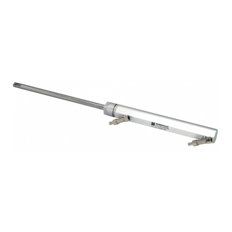
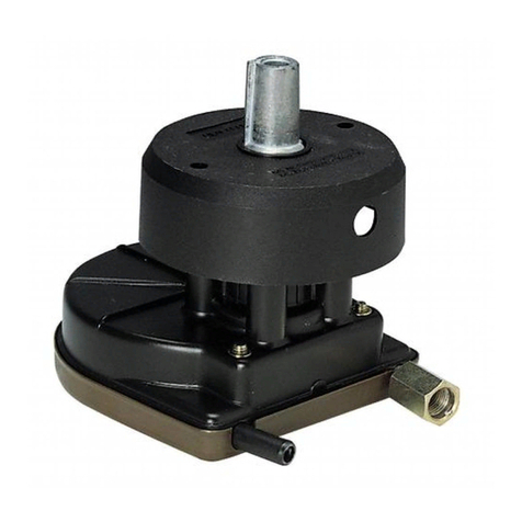
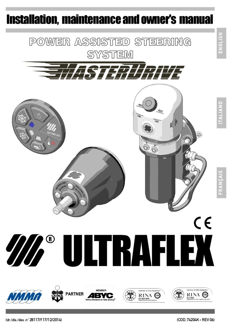
Ultraflex UC 128-TS Manual

HYDRAULICCYLINDERFOR
OUTBOARDENGINES
UC128-TS
(Dr.No.22635/p27/07/2018)
InstallationandMaintenanceManual
ENGLISH
PARTNER
(REV.1)

UFLEXUSA
Sarasota,FL34243 -6442 ParklandDrive
DearCustomer,
Wewould liketothankyouforchoosingan ULTRAFLEX SpAproduct.
ULTRAFLEX SpAhasbeenaleaderinsteeringsystemsforpleasureandprofessionalboatsformany
years.
All ULTRAFLEX SpAproductsaredesignedandmanufacturedtoensurethebestperformance.
To ensureyoursafetyandtomaintainahighqualitylevel, ULTRAFLEX SpAproductsareguaranteedonly
iftheyareusedwithoriginalspareparts(see attacheddocument"ApplicationSpareParts").
Thequalitymanagementsysteminvolvesallthecompanyresourcesandprocesses startingfromthe
design,inorderto:
- ensureproductqualitytothecustomer;
-maintainandimprove thequalitystandardsconstantly;
-pursueacontinuousprocess improvementtomeetthemarketneedsandtoincrease thecustomer
satisfaction;
-constantlytesttheproductstoverifytheirconformitywiththe2013/53/EU.
"Establishedin1989 UFLEX USAis aleaderinsteeringandcontrolsystemsforthemarineindustry.
Withfull manufacturingcapabilities inSarasota, Florida, UFLEX USAcansupportall sectorsofthemarine
industryregardlessofvolumeand/orproductrequirements.And,as anaffliateofthe ULTRAFLEX Group,
UFLEX USAhas tremendousresources todrawuponfornewproductdevelopmentinhydraulics, electronics
andmanyothertechnologies.
Innovative productdesignandunparalleleddedicationtoqualitycustomerservice andproductsconti-
nuetobecornerstoneof UFLEX USA's growth.Todayourproductscanbefoundas originally installed
equipmentonmanyofthemostwidelyknownandrespectedboatbrandsintheworld.
Aftermarketpartscanbesourced fromtrainedandexperienceddistributornetwork troughoutNorth
andSouthAmerica.
Ourdedicationtoprovidingthehighestqualityproductsandservice is onlymatchedbyourcommitment
todevelopingnewproductsemployingthelastestmaterialsandtechnologytoenhanceourcustomer's
boatingexperience. Fromsteeringwheelstosophisticatedelectronic controls, UFLEX USAhas everything
youneedtomakesurethatyourboatlooksandperformit's bestformany,manyyears."

HYDRAULIC CYLINDERFOROUTBOARD ENGINE -page 3 of 26
ENGLISH
InstallationandMaintenanceManual
SECTION1-PRODUCTDESCRIPTION
1.1 HYDRAULICSTEERINGSYSTEMOPERATION.................................................................................8
1.2 WARNINGSFOR THECORRECTPRODUCTUSE......................................................................8
1.3 CONFIGURATIONS.........................................................................................................................9
1.4 UC128-TSCYLINDERDESCRIPTION......................................................................................................10
1.5 TECHNICALFEATURES..........................................................................................................................10
TABLEOFCONTENTS
SECTION2-TRANSPORT
2.1 GENERALWARNINGS.............................................................................................................................11
2.2 PACKAGINGCONTENTS....................................................................................................................11
SECTION5-MAINTENANCE
5.1 ORDINARY MAINTENANCE................................................................................................................23
5.2 HEADREPLACEMENT.........................................................................................................................23
5.3 TROUBLESHOOTING.........................................................................................................................24
SECTION3-INSTALLATION
3.1 MINIMUMTRANSOMREQUIREMENTS.........................................................................................12
3.2 NECESSARYTOOLS.......................................................................................................................12
3,3 STANDARD (STARBOARD)CYLINDERINSTALLATION................................................................13
3,4 HOSEINSTALLATION................................................................................................................................16
3.5 TYPEOFINSTALLATION...........................................................................................................................17
3.6 FILLINGAND PURGING.......................................................................................................................18
3.6.1 POSITIONINGOFTHEOILBOTTLE...................................................................................19
3,6,2 SINGLESTEERINGSTATION/SINGLECYLINDER......................................................................................19
3.6.3 SINGLE STEERINGSTATION/DUALCYLINDER..............................................................................20
3.6.4 DUALSTEERINGSTATION/SINGLECYLINDER.........................................................................................20
3.6.5 DUAL STEERINGSTATION/DUAL CYLINDER............................................................................................21
3.7 GENERAL RECOMMENDATIONS................................................................................................................21
SECTION4-SAFETYWARNINGS
4.1 SAFETY WARNINGSDURINGUSEAND INSTALLATION.......................................................................22
4..2 CLOTHING................................................................................................................................22
SECTION6-DISMANTLING
6.1 DISMANTLING...............................................................................................................................26
!
DOCUMENTREVISIONS...................................................................................................................................4
MANUALUSEANDSYMBOLSUSED................................................................................................................5
INTRODUCTION.................................................................................................................................6
WARRANTY................................................................................................................................6
IMPORTANT:
Theadditionaldocuments"ApplicationGuide"and"SparePartsList" areattachedtothismanual.

page 4 of 26 -HYDRAULIC CYLINDERFOROUTBOARD ENGINE
ENGLISH
InstallationandMaintenanceManual
DOCUMENTREVISIONS
Rev. Date Revisiondescription
0
1
20/02/2006
27/07/2018
Firstedition
Newversionwith removableheads

HYDRAULIC CYLINDERFOROUTBOARD ENGINE -page 5 of 26
ENGLISH
InstallationandMaintenanceManual
Inthismanualthefollowingsymbolsareusedtoensuretheusersafetyandtoguarantee thecorrect
operationoftheproduct:
MANUALUSE AND SYMBOLSUSED
THEINSTALLATION AND MAINTENANCE MANUAL is thedocumentaccompanyingtheproductfromitssale
toitsreplacementanddischarge.Themanualis animportantpartoftheproductitself.
It is necessarytoreadcarefully themanual,beforeANY ACTIVITYinvolvingtheproduct,handlingand
unloadingincluded.
STERN
BOW
STARBOARD PORT Thepictureasideexplainsthemeaningofsome
nauticalwordscontainedinthismanual.
DANGER ImmediatehazardswhichCAUSEseverepersonalinjuryordeath.
WARNING
CAUTION
Thesymbolasideindicates all theoperationswhichmustbecarriedout
byqualifiedorskilledstaff,inordertoavoidhazards.
Werecommendtrainingthestaffinchargeoftheproductinstallation
andcheckingtheirknowledge.
NOTICE Importantinformationforthecorrectinstallationandformaintenance,that
doesnotcauseanydamage.
Denotes thatahazard existswhichcanresult ininjuryordeathifproper
precautionsarenottaken.
Denotesareminderofsafetypracticesordirectsattentiontounsafe
practices whichcould result inpersonalinjuryordamagetothecraft or
componentsortotheenvironment.

page 6 of 26 -HYDRAULIC CYLINDERFOROUTBOARD ENGINE
ENGLISH
InstallationandMaintenanceManual
INTRODUCTION
This installationandmaintenance manualrepresentsanimportantpartoftheproductandmustbeavailable
tothepeopleinchargeofitsuse andmaintenance.
Theusermustknowthecontentofthis manual.
UFLEX declinesallresponsibilityforpossiblemistakesinthis manualduetoprintingerrors.
Apartfromtheessentialfeaturesofthedescribedproduct, UFLEX reservestherighttomakethose
modifications, suchas descriptions, detailsandillustrations, thatareconsideredtobesuitableforits
improvement,orfordesignorsales requirements, atanymomentandwithoutbeingobligedtoupdatethis
publication.
ALL RIGHTSARE RESERVED.Publishingrights, trademarks, partnumbersandphotographs of UFLEX products
containedinthismanualare UFLEX property.
Greatcarehas beentakenincollectingandcheckingthedocumentationcontainedinthismanualto
makeitas completeandcomprehensibleaspossible. Nothingcontainedinthis manualcanbeinterpreted
as warrantyeitherexpressedorimplied-including,notinarestrictedway,thesuitabilitywarrantyforany
specialpurpose.Nothingcontainedinthismanualcanbeinterpretedasamodificationorconfirmationof
thetermsofanypurchasecontract.
Toensurethecorrectproductandcomponentoperation,theproductmustbeinstalledbyqualifiedstaff.
Incaseofpartdamageormalfunction,please contactthequalifiedstafforourTechnicalAssistance
Service.
WARNING
WARRANTY
1.TwoYearLimitedWarranty. UFLEX USA, Inc.warrantsthatall productsmanufacturedby UFLEX USA,
Inc. or UFLEX S.p.A. andsold by UFLEX USAtotheretailpurchaser("Purchaser")thatfortwo(2)yearsafter
thedateofmanufacturetobefree fromdefectsduetomaterialorworkmanship,subjecttotheexclusions
below.ImproperinstallationAVOIDSthiswarranty.Installationshould onlybeattempetedbyatrained
andqualifiedtechnician.
2. Exclusions. This limitedwarrantydoes notcover anddoes notextendtoanyofthefollowing:
(a) Failurecausedby normalwearandtear,climaticconditions,misure, neglect,lackofproper
maintenance, accident,fireorothercasualtydamage, racing,overloading,negligence, modification,
beachingorgroundingofvessel,collision,impact,towing,actsofwarorhostilities;
(b) componentsnotmanufacturedby UFLEX USA,Inc.,oritsaffiliates;
(c) costofremovalorreinstallationofanycomponent(includingcomponentsmanufacturedby UFLEX
USA,Inc.)ordisassemblyorreassemblyoftheunitcontainingthecomponent;
(d) componentsnotmanufacturedby UFLEX USA, Inc. or UFLEX S.p.A., whetherornotwarrantedbythe
othermanufacturer;
(e) anyproductwhichhasnotbeenproperlyinstalled.
TECHNICALASSISTANCE SERVICE
North-South-CentralAmerica:
UFLEX USA
6442ParklandDrive
Sarasota,FL34243
Tel:+1.941.351.2628
Fax: +1.941.360.9171
Email: sales@uflexusa.com
www.uflexusa.com
UFLEX S.r.l.
ViaMiliteIgnoto,8A
16012 Busalla(GE)-Italy
Tel:+39.010.962.01
Fax: +39.010.962.0333
Email: service@ultraflexgroup.it
www.ultraflexgroup.it

HYDRAULIC CYLINDERFOROUTBOARD ENGINE -page 7 of 26
ENGLISH
InstallationandMaintenanceManual
3. Limitations. THEREPAIROR REPLACEMENT OFDEFECTIVE PARTSSHALL BE PURCHASER'SSOLE AND
EXCLUSIVEREMEDY AND UFLEX USA,INC,'SSOLEANDEXCLUSIVE LIABILITYUNDER THISWARRANTY.
LABOR FOR REPLACEMENT IS NOT INCLUDED. UFLEX USA, Inc.'s obligationunderthis warrantyis limited
totherepairorreplacement(at UFLEX USA, Inc.'s soleelection)ofanycovereditemfoundtobedefective,
whendeliveredby Purchaserpursuanttowrittenauthorizationandinstructionsfrom UFLEX USA, Inc.,
shippingprepaidto UFLEX USA,Inc.'s plantorotherdesignatedrepairfacility.Repairedorreplaced
itemsarewarrantedasprovidedhereinfortheunexpiredportionoftheapplicablewarrantyperiod.
THISWARRANTY, AND THERIGHTSAND REMEDIESUNDER IT, IS EXCLUSIVE AND IS GIVEN INPLACE OF
ALLOTHERWARRANTIES,WHETHEREXPRESSORIMPLIED,INCLUDINGANYIMPLIEDWARRANTYOF
MERCHANTABILITYOR FITNESSFORPARTICULARPURPOSE, WHETHERARISINGBYLAW,CUSTOM,
CONDUCT OR USAGE OFTRADE, PURCHASER'SREMEDIESSHALL BE LIMITED ASSTATED HEREINAND
UFLEX USA, INC. SHALL NOT BE LIABLE FOR ANY INCIDENTAL, CONSEQUENTIAL OR INDIRECT DAMAGES
ORLOSSESRESULTINGFROMDEFECTS.THERETAILSELLERIS NOTACO-WARRANTORAND ISNOT
AUTHORIZED BY UFLEX USA, INC. TO AMEND OR MODIFYTHISLIMITED WARRANTY INANY MANNER.
4.TransferabilityofWarranty. Thislimitedwarrantymay notbetransferredtosubsequentpurchasers.
5.Miscellaneous. UFLEX USA,Inc. is anaffiliateof UFLEX S.p.A. UFLEX,USA,Inc.,reservestherighttomake
changes inthedesignandconstructionofitsproducts atanytime, withoutnotice andwithoutanyobligation
toincorporatesuchchanges intoproductsofpriormanufacture. Thislimitedwarrantyapplies tonew
componentssold by UFLEX USA,Inc.. This limitedwarrantycontainstheentireagreementsbetween
UFLEX USA, Inc.andPurchaserandsuspersedes allprioragreements,discussions, negotiations,
commitmentsandrepresentations, whetheroralorwritten,betweenthemregarding UFLEX USA, Inc's
warranty.If anyprovisionofthislimitedwarranty, ortheapplicationofit,isdeterminedtobeinvalidof
unenforceableforanyreason,theremainderofthislimitedwarrantyandtheapplicationofitshallnot
beaffected.
6. Ultron3000 andPowerC. TheUltron3000and"PowerC-UserandInstallationManual" describes
activities,operations,technical specificationswhichmustbefollowedduringtheinstallationand/or
usageoftheproduct,inordertokeepavalidwarranty.Descriptionsanddrawingsinthatmanualare
suitabletoallowinstallationanduse oftheproducttoskilledpersons. Incaseofdoubtand/orforany
information,pleasecontactourTechnicalService.
All communicationsandnoticesfromPurchaserregardingthis limitedwarrantyshould besentto: UFLEX
USA, INC., 6442 ParklandDrive, Sarasota, FL34243; (941)351-2628.
Return policy
Anyproductthatis presumeddefective shouldbereportedto UFLEX USAwithin48 hoursofreceiptor
discoveryinthefield.Uponnotification UFLEX USAwill attempttotroubleshoottheproblemwithourcustomer
overthephone.If weareunabletoresolvetheproblem UFLEX willissueaReturnGoodsAuthorization
numberandwerequirethattheproductinquestionbereturnedto UFLEX withallitspartsinitsoriginal
packaging.Theproductshouldbereturnedfreightprepaidto:
UFLEXUSA
RGA Department-RGA #
6442ParklandDrive
Sarasota, Florida34243
Uponreceipt UFLEX will examinetheproducttodeterminethecause ofthedefect.If theproductis determined
tohaveadefectinworkmanshipormaterial,itwillberepairedatourdiscretion.
Ourwarrantydoes notcoverlabor,towingorotherexpenses. Further,itdoes notcoverproductsthathave
beenimproperly installed,damagedininstallation,misapplied,ormisused.
Ourproductsarenotintendedforuseinracingapplications.

page 8 of 26 -HYDRAULIC CYLINDERFOROUTBOARD ENGINE
ENGLISH
InstallationandMaintenanceManual
ULTRAFLEX hydraulicsteeringsystemsshouldnotbeusedinracingapplications.
To avoidproductdamage,donotdisassemblepre-assembledcomponents.
All UFLEX steeringsystems mustnotbe installedonboatsequippedwithengines whose maximum horsepower
ishigherthanthehorsepowerratingapprovedby boatmanufacturer.
1.2 Warningsfortheproductcorrectuse
Beforebeginningtheinstallation,checkthemountingcompatibilityoftheUC128-TScylindertotheengine
byconsultingtheattachteddocument"ApplicationGuide"containedinthepackaging.
Do notmodifythesteeringcylinderinanyway tofitittoyourengineapplication,otherwise thecylinderwill
nolongeroperateinsafetyanditwillendangertheboatandtheoccupants.
WARNING
WARNING
WARNING
DANGER
DANGER
1PRODUCTDESCRIPTION
1.1Hydraulicsteeringsystemoperation
All ULEX hydraulic steeringsystemsaredesignedinconformitywithUNI-EN-ISO10592andA.B.Y.C. P21 regulations.
AllUFLEXsteeringsystemscanoperateattemperatures between-18°C(0°F)and+77°C(+170°F).All the
componentsaremadeforthemarineenvironment,usingmaterialsandworkingprocesseswhichoffer
longlifeandsafetyunderthemostextremeconditions.Ahydraulicsteeringsystemconsistsofasteering
pump,acylindertiedtotherudderortotheoutboard orsterndrive
engineandtheconnectinghoses(see picture).Undernormal
operatingconditions, aturnofthesteeringwheelwillpumptheoil,
whichflowsinthroughthehosestothecylinder,accordingtothe
turndirection.Withtheconsequentcylindermovementtheoilwill
flowtothepumpthroughthehoses andatthesametimemoves the
engineorthehelmwhichareconnectedtothecylinder.Thepumps
areequippedwithavalve,whichpreventsoutgoingfluidfrom
returningalongthesamehose.It also allowstheoperationofthe
steeringsystemswithtwoormoresteeringstations.Thecylinders
aredoubleactingandmaybebalancedorunbalanced.Inthe
unbalancedcylindersthetwochambershave differentvolumes and
so they needadifferentnumberofturnsofthesteeringwheelanda
differentrotationeffort.Thebalancedcylindershavesamenumber
ofsteeringwheelturnsinordertomove thehelmfromthecenterto
theendstrokeinthetwooppositedirections. Awell balancedsteeringsystemneedsacorrectchoice ofthe
pumpforthecylinder. UFLEX produces differentpumpmodels,whichhave differentcapacity(cm3ofoilmoved
eachsteeringwheelturn)andforeachtype ofinstallation.Whilechoosingthepumpitis importantto
considerthecylindervolume. Thenumberofstarboardandportturnsisdeterminedbytheratiobetween
thecylindervolumeandthepumpcapacity.
Example:ifthepumphas acapacityof28cm3 [1,7cu.in.]andthecylinderhas avolumeof120cm3 [7,3cu.in.],the
formulalookslikethis:120/28=4,2. Accordingly,thesteeringwheelwillturn4,2timesbeforethecylinder
willcompletelyturnfromonesidetotheother.Incaseofinstallationswithdoublecylindersconnectedin
parallelthecylindervolumemustbeadded.Applicationswithlessthan4turnsarenotrecommended,as
theyneedahighereffort,alsoapplicationswithmorethan8turnsarealso notrecommended,as the
response oftheboattosteeris slowly.Themaximum operatingpressureis 7,0MPa(70bar)(1000PSI).
l
engine
hydraulic
hose
cylinder
l
l
l
pump

HYDRAULIC CYLINDERFOROUTBOARD ENGINE -page 9 of 26
ENGLISH
InstallationandMaintenanceManual
1.3Configurations
Thehydrauliccylinderforoutboard engineUC128-TSmodelcanbeinstalledwithdifferentconfigurations
accordingtothenumberandthetypeofengines usedwithasingleordualenginesteeringsystem.
Thepossibleconfigurationsare:
Onrequest,tripleoutboardengineapplicationsareavailable.Fordetailedinformation,pleasecontact
UFLEX Assistance Service.
NOTICE
STEERINGSTATION
NUMBER
S
I
N
G
L
E
S
T
A
T
I
O
N
ENGINE NUMBER
With
SINGLE STANDARDCYLINDER(starboardversion)
With
SINGLESTANDARDCYLINDER(
starboardversion
)
and
TIEBAR
With
DUALCYLINDER(starboard+port)
upto300hpmax
orupto
55 m.p.h.
non-counterrotating
engines upto
300hpmaxofcombined
horsepowerorupto
55 m.p.h.
counterrotating
enginesupto500 hp
maxofcombined
horsepowerorupto
55 m.p.h.
non-counterrotating
engines upto
500hpmaxofcombined
horsepowerorupto
55 m.p.h.
counterrotating
enginesupto600 hp
maxofcombined
horsepowerorupto
65 m.p.h.
MAINSTATION
ADDITIONAL
STATION
D
U
A
L
S
T
A
T
I
O
N
DANGER
Dualengineinstallationsrequiretheuse ofatiebar.
D
U
A
L
E
N
G
I
N
E
S
I
N
G
L
E
E
N
G
I
N
E

page 10 of 26 -HYDRAULIC CYLINDERFOROUTBOARD ENGINE
ENGLISH
InstallationandMaintenanceManual
1
2
3
7a
7c
4
5
6
7b
1.4UC128-TScylinderdescription
UC128-TSisahydraulicoutboard frontmountcylinderwhichhasbeendesignedandmanufacturedtobe
usedasacomponentinthehydraulicsteeringsystems,asdescribedinthepreviousparagraph.
Thecylinderis installedtothetilt tuberodoftheavailableengines onthemarketas shown intheattached
document"Applicationguide".Itis possibletomeetall thedifferentcylinderapplicationsduetothethree
differentlinkarmsandaproperspacerkit.Forthedualengineapplication,thesinglecylindermustbe
mountedwithatie bar(see par.1.3)ortwocylinders(standard +port) connectedbyatie barcanbeused.
Inthestandard versionthelinkarmis mountedonthestarboard side, whileintheportversionitis mounted
ontheportside(see pictureinpar.1.5).Thefollowingpictureshowsthemaincylindercomponents:
Cylinderbody
Bleeders
Bull horns
Tilttuberod
Spacers
Adjustmentcollar
Straightlinkarm(UC128-TS/1)
Shapedlinkarm(UC128-TS/2)
Curvedlinkarm(UC128-TS/3)
1
2
5
6
3
4
7a
7c
7b
1.5Technicalfeatures
544 mm (21.43")
76.2 mm (3.00")
STANDARDVERSION(STARBOARD) PORT VERSION
SPECIFICATIONS UC128-OBF/1 -/2-/3
Volume 120cc -7.8 cu. in
Outputforce 450 Kg-992 lbs (@70 bar)
Insidediameter 35mm -1.37"
Stroke 198 mm -7.79"
Oil
OL150 Ultraflex
*Thecylinderoutputforceisatheoreticalforcewithasystempressureof105bar.Thisforce doesnot
correspondtotheonenormallyusedbythesystembutitrepresentsthelimitingconditionsofuse.
CAUTION

HYDRAULIC CYLINDERFOROUTBOARD ENGINE -page 11 of 26
ENGLISH
InstallationandMaintenanceManual
Thepackagingmustbedisposedofaccordingto theexistinglaws.
CONTENTSOFTHESTANDARDPACKAGING:
A)No.1cylinderbodywithrod,fittingsandbullhorns;
B)No.1linkarmkitcomposedof:
-No.1linkarm;
-No.2allenscrewswithNo.1safetyscrewand
lock washer;
-No.1bolt+nut;
-No.1kitforSuzukiengines (notTS/3version);
C)No. 1spacerkitcomposedof:
-No.8plasticspacers;
-No.2 steelspacers;
-No.1ringnutforadjustementcollar;
D)No.2capsforthecylinderbody;
E)No.2bolts+No.2lockwashers;
F)No.2locknuts+n°2washers;
2.1 Generalwarnings
2TRANSPORT
2.2 Packagingcontents
Beforeusingtheequipmentcheckthattheproducthasnotbeendamagedduringtransport.
Alsomakesurethatallthestandardcomponentsareinthepackaging(seelist).Incaseofdamage,
notifytheclaimtotheforwarderandinformthesupplier.
WARNING
Thestaffinchargeofhandlingmustoperatewithprotectivegloves andsafetyshoes.
CAUTION
Theproductweightwithitspackagingis 8kg (18 pounds)andso itcanbehandledmanually.
A
B
D
E-F
C

page 12 of 26 -HYDRAULIC CYLINDERFOROUTBOARD ENGINE
ENGLISH
InstallationandMaintenanceManual
3INSTALLATION
3.1Minimumtransomrequirements
Thefollowingpictureshowstheminimum splashwell dimensions. These dimensionsmustberespectedin
ordertopreventthecylinderfrombeingdamagedwhentheoutboard engineis completelytiltedupwards.
Thepictureshowsalso theminimum transomdimensions, neededfortheinstallationandthecorrect
operationoftheenginesteeringcylinder.
ENGINE JACK PLATE APPLICATION TO THETRANSOM.
Ajackplateinstallationwill changeall theapplicationclearances. Anewclearance checkmustbecompleted
withthetiltingoftheengineinconjunctionwiththeverticalmovementofthejackplateinall thepossible
positions.Ifthesteeringcylindercomesintocontactwiththesplashwell,transomand/orjackplate, stop
theinstallationimmediately! Usethejackplatemanufacturer'sinstructionstolimittheupperorlower
directioninwhichtheinterferenceoccurs.Ifthisisnotpossiblepleasecontactspecializedstaff.
WARNING
EngineNo. A B C
1560 mm - 21.25" 152mm -5.98" 152 mm -5.98"
2 1110mm - 43.70" 152mm -5.98" 152 mm -5.98"
MINIMUM SPLASHWELL DIMENSIONREQUIREMENTS
3.2Necessary tools
C
B
A
³
90°
Allenwrench
[1/8”]
Allenwrench
8mm [5/16”]
Openend
wrench
19mm
Pliers
Openend
wrench
11/16”
Openend
wrench
9/16"
Phillips
screwdriver
Torquewrench
MOLYKOTE® 1000
Openend
wrench
3/4"
Openend
wrench
14mm

HYDRAULIC CYLINDERFOROUTBOARD ENGINE -page 13 of 26
ENGLISH
InstallationandMaintenanceManual
3
4
l
l
3.3 Standard(starboard)cylinderinstallation
Duringtheinstallationphases use only stainless
steeltoolstoavoidthecorrosionofthemetalparts.
CAUTION
1Incase ofsinglecylinderinstallationmountthe supplied
capsonthecylinderbodyasshowninthepicture.
CAUTION
Duringthisphaseanoilleakfromthefittingscan
occur.Thisoilmustnotbedischargedintothesea in
anycase.
2Afterremovingtheprotectivecapsofthe
fittings, manuallycentertherod(1)onthecylinder
body(2).
3Mountthelinkarm(3)onthecylinderbodyas
shown inthepictureby meansofthesuppliedscrews
(4). Tightenthe suppliedscrews byusinga 8mmAllen
wrenchwithatorqueof76[Nm](56[lb ft]).
4Positionthelockwasher(5)andtightenitwith
thescrew(6),byusingLoctite 270(torque 3[Nm](2
[lb ft]).
5Positiontheenginestraightsothatitsarmis
perpendiculartothetransom.
Theoperationsdescribedinpoints3and4mustbe
carriedoutonlyduringthefirstinstallation.Thechoice
ofthelinkarmdependsontheenginetype(see
attachedApplicationGuide).Donotdisassemblethe
armfromthecylinderbody inanycase.
WARNING
7
8
l
l
6Withreferencetotheapplicationinstructions
containedintheApplicationGuide,connectthelink
armtothetillerarmbymeansofthescrew(8),
tightenitby usinga14mmwrenchwithatorqueof
54[Nm](40 [lb ft]).Tightentheself-lockingnut(7)by
usinga9/16"wrenchwithatorqueof27[Nm](20
[lb ft]).Aftertighteningthelocknut(7),check forthe
righttorque54[Nm](40 [lb ft]) ofthescrew(8). 7Grease thetilt tuberod(9),by usingmarine
grease.
8Insertthetilttuberod(9)intothetilt tube.
Inordertotightenscrew(8)andtheself-locking
nut(7)onthetillerarm,askyourmechanicthe
maximum allowedtorque. If itis lowerthanthat
showninthismanual,alwaysusethetorque
indicatedbyyourmechanic.
WARNING
Itisimportanttocheckperiodically,atleastevery3
months(orevery monthforprofessionaluses),the
righttorqueofthis screw(8)andofthelocknut(7).
WARNING
If theself-lockingnut(7)is disassembled,replace
it.(Contactourtechnicalassistanceservice,see
page5).
CAUTION
1
l
l
2
l
6
l
5
9
l

page 14 of 26 -HYDRAULIC CYLINDERFOROUTBOARD ENGINE
ENGLISH
InstallationandMaintenanceManual
Boththestainless steelspacersmustbepositioned
towardsthetilt tubeontheoppositesideofthe
bull hornstoavoidtheirwearduringenginelifting
andlowering.
9Fitthesetscrew(10)ontheadjustmentcollar
(11)andscrewittotherightsideofthetilttube
untilitcomesintocontactwiththetilttubestop
nut,evenincaseofportapplications.
10Withreferencetothe'"ApplicationGuide"
choosethespacersforthetilt tuberod.
11Inserttherightandleftbullhorns(12)by
connectingtherodandthetilt tuberodas shown
inthepicturewithouttighteningthem.
12Choose andcheckthespacerstofill thegap
betweenringnutandbullhorndandd2
between
tilt tubeandbullhornconsideringthethickness of
thestainless washer.
13Once thecorrectspacershavebeenchosen,
removethebull horns.
WARNING
14Inserttheplasticandstainlesssteelspacers
andthetwostainless washeronthetilt tuberod.
15Inserttherightandleft bull horns(12)by
connectingrodandtilttuberodas shown inthe
picture.
Inthis phase ensurethatthecylinderbodyis
centeredontherodandthattheengineis
perpendiculartothetransom.
NOTICE
Alwaysleaveaminimumclearancebetween
spacers andbullhorninorderto allowtherodtilting
inthetilt tube.
NOTICE
LARGE MEDIUM SMALL
1,6 mm /0,06"
3,2 mm /0,12"
8,1 mm /3,1"
Thenumberandpositionofthespacersshown in
theApplicationguideareindicativeonly.
l
l
10
11
l
12
12
l
d
2
d
12
l
12
l

HYDRAULIC CYLINDERFOROUTBOARD ENGINE -page 15 of 26
ENGLISH
InstallationandMaintenanceManual
15
16
l
l
14
13
l
l
16Insertthewashers(13)onthetwoendsofthe
tilt tuberod,grease thenutthread(14)with
someanti-seize greasetype MOLYKOTE® 1000ora
similarone,screwthembyusinga3/4"wrench
andtightenthemwithatorqueof70[Nm](52[lb ft]).
19Unscrewtheadjustmentcollar(11)andbring
itintocontactwiththestainless washer,untilthe
clearanceiseliminated,
20Check thecorrectcylinderinstallationbymoving
manually theengineontherightandontheleft.
WARNING
22Bendthetabsofthe
lockwashers(15)
bringingtheminto
contactwiththescrew
headandtakingcarenot
todamagethebull horns
whileusingthepliers.
Theenginemuststopthroughthe
cylinderendstrokewithout
comingintocontactwiththe
mechanical stop(17)onthe
engine.
17
l
NOTICE
Otherwise itis necessarytomodifytheinstallation,
bychangingthethicknessofthespacersandby
repeatingtheprocedurefrompoint13.
23Checkagainthecorrectenginemovement
bothduringtheright/left rotationandduringthe
tilting.
WARNING
Inthis phase clearance should beenoughtoavoid
frictionsbutitshould notbeexcessive since itcould
cause engineinstability. Incase ofcontactwiththe
transom,stoptheinstallationandcontactthe
specializedstaff.
NO CONTACT
NOTICE
Do notuse anytoolforthis operation.
NOTICE
Therotationmustbeassymmetricas possible
betweenportandstarboard so thatthesteering
angleis thesameonbothsides.
If theself-lockingnuts(14)aredisassembled,
replace them.(Contactourtechnicalassistance
service,see page5).
WARNING
17Positionthelockwashers(15)andlockscrew
(16)byusinga 19mmwrenchwitha torqueof70[Nm]
(52[lb ft])aftergreasingthemwithanti-seizegrease
typeMOLYKOTE® 1000orasimilarone.
Ifwhiletiltingtheengineisblocked,reducethe
overall dimensionsofthespacers.
NOTICE
Thelockwashertabsmustbebentafterwards(see
point22).
WARNING
18Checkthecorrecttiltingoftheengine.
21Tightenthesetscrew(10)ontheadjustment
collar(11)bya1/8"Allenwrenchwithatorqueof
3[Nm](2[lb ft]).
NOTICE
Checkperiodicallytheclearanceabsencebetween
theringnutandthetilttubeotherwise eliminate
theclearance throughtheadjustmentringnut(11).
10
11
l
l
15
l

page 16 of 26 -HYDRAULIC CYLINDERFOROUTBOARD ENGINE
ENGLISH
InstallationandMaintenanceManual
3.4Hoseinstallation
Thetwofittingsmountedonthecylinderbodyarealreadyorientedandarereadytobeused.If forpractical
reasonstheorientationmustbechanged,doasfollows:
1.loose thelocknut(A)byusinga11/16"wrench;
2.orientthefittingsaccordingtotherequirements;
DANGER
Do notunscrewthefittingsmorethanoneturn(360°).
3.tightenagainthestopnutwithatorqueof20[Nm](15[lb ft]) untilthewashercomes intocontactwithit.
Screwthehoses onthecylinderfittingswithatorqueof20[Nm](15[lb ft]) accordingtothefollowinginstructions:
-minimumhosebendradius250mm;
- nointerference duringenginetilting;
-nointerference withthetransom;
NO
WARNING
Anexcessivehosebendcould result initsinternalbreakingwhich
will cause abadoperationofthesystem.Inthis case itis necessaryto
replace thedamagedhose.
min. bend
radius 250 mm
l
A

HYDRAULIC CYLINDERFOROUTBOARD ENGINE -page 17 of 26
ENGLISH
InstallationandMaintenanceManual
3.5Typeofinstallation
TheUC128-TShydraulic cylinderforoutboard engines canbeinstalledwithdifferentconfigurationsaccording
tothenumberandthetypeofengines usedwithasingleordualsteeringsystem.Thepossibleconfigurations
are:
CAUTION
Connecthosesasshowninthefollowingpictures:
SINGLE STATION/DUALCYLINDER:
SINGLE STATION/SINGLE CYLINDER:
DUALSTATION/DUALCYLINDER:
1.helm
2.starboardcylinder
3."T"fittings
4.kitOB
1.helm
2.starboardcylinder
3.portcylinder
4."T"fittings
1.upperstationhelm
2.lowerstationhelm
3.starboardcylinder
4."T"fittings
5.kitOB-2S
6.kitOB
3
4
1
2
1
2
3
2
2
3
1
l
1
l
l
l
3
l
l
l
ll
5
DUALSTATION/SINGLE CYLINDER:
4
l
l
l
4
l
l
l
l
l
l
l
l
l
l
l
l
5
6
l
76
l
l
l
l
7
8
5l
1.upperstationhelm
2.lowerstationhelm
3.starboardcylinder
4.portcylinder
5."T"fittings
9
l
l
4
4
5. "T"fittings
6. tie bar
7. kitOB-2C
8.kitOB
8
l
8
l
6l
6l
6
l
6l
6."T"fittings
7.tie bar
8.kitOB-2C
9.kitOB-2S
10.kitOB
l
10
l
10
l
10
10 l

page 18 of 26 -HYDRAULIC CYLINDERFOROUTBOARD ENGINE
ENGLISH
InstallationandMaintenanceManual
3.6Fillingandpurging
Afterthefirstinstallationandaftermaintenance operationsitisnecessarytofill thesystemwithhydraulic
oil.This operationmustavoidtheairinthesystem,toensurethegoodsystemoperation.Thehydraulic
systemmustbefilledfromthehighestpointofthesystem,whichmeansfromtheuppersteeringstation.
To avoidairbubbles intheoil,itisnecessarytofill thetankslowly.
Thefillingandbleedingoperationsmustbecarriedoutatleastbytwooperators
Use UFLEX oilorothercompatibleoils.
ThefillingandpurgingoperationscanbefacilitatedbyusingtheautomaticpurgingequipmentBUBBLE
BLUSTERâ (suppliedseparately).
HydraulicoilOL150hasbeenspecificallyformulatedfor UFLEX toensurehighqualityperformancelevelof
ULTRAFLEX productsthroughouttime.
Itsspecial"ZincFree"formulaenhancesprotectionagainstmarineoxidation.Thespecialmixofanti-wear
andstabilizingcomponentsofOL150allowensuringgreatresultsasfarastheproductdurationand
performances areconcernedinseveralenvironmentalconditions. UFLEX hydraulic oilcomplies withstandard
ISO10592concerninghydraulicsteeringsystems. UFLEX isnottobeheldresponsibleforanydamages or
performancedeteriorationifoilsdifferentfromOL150areused.
Do NOT use ATFDexronII transmissionoilsorbrakeoilswhichcouldcause thesteeringsystemseizing.
OilswhicharecompatiblewithOL150 UFLEX are:
-Shell TellusT15 andShell TellusT22
-MobilDTE 11M
ULTRAFLEX will notbeabletoensurethecompatibilityoftheabove mentionedoilswithOL150 iftheoil
manufacturersvarytheirformulation;inparticular,itwill notbeabletoensureitscompliance withstandard
ISO10592concerninghydraulic steeringsystems.Undernocircumstances UFLEX istobeheldresponsible
foranydamages orperformancedeterioration.
Inthedays afterthefilling,checktheoillevel;ifnecessarytopoff thesystem.
Atthebeginningtheoillevelcanlower,assmallamountsofaircanbereleasedinahomogeneousway.
Accordingtothetypesofinstallation,itis necessary tocarry outthedifferentbleedingprocedures,as itfollows.
CAUTION
WARNING
DANGER
NOTICE
DANGER
NOTICE

HYDRAULIC CYLINDERFOROUTBOARD ENGINE -page 19 of 26
ENGLISH
InstallationandMaintenanceManual
3.6.1 Positioningoftheoilbottle
pin
oilbottle
hose
spout
filling
connection
-Removethepumpcapandinsertthefittings.
- Attachthespouttoanewbottleofhydraulic oilandconnectthehose tothe
fittingsandthebottlespout.
-Turnthebottleupsidedown andpierce itwiththepin,as shown inthe
picture,toeasetheoilpassagetowardsthepump.
Fill thepumpuntilnoairbubbles arevisibleinthehose.
Whilereplacingtheoilbottle,duringthefillingprocess,closeallthebleed
valvesofthecylinder/s. To bleedthesystem,checkthatoilis always present
inthefillinghose. If someairis inthesystemduringthebleedingprocess, the
wholebleedingprocessmustbestartedagain.
WARNING
Replacethebottlebeforeitemptiesanduserecoveredoilonly after24 hours.
CAUTION
To carry outthis operation,itis necessary touse theoilfillingkit(1needle, 1transparent
pipe, 1pipeconnectionand1spoutfortheoilbottle).This kitis NOTsupplied.
-Unscrewthetwobleedvalve protectionsandloosen1.5 turnsmax. thenuts
"A"ofthetwobleedvalves.
- Unscrewthetwobleedvalvesandmanuallypushthecylinderbodytoone
sideuntilitstopsas shown inpicture1.
-Positiontheoilbottleasexplainedinparagraph3.6.1.
-Close thebleedvalve onthecylinderendstrokesideandputapurgedoil
tankneartheotherbleedvalve(as shown inpicture2).
-Turnthesteeringwheelslowly(as shown inpicture2)so thattheoil
cancomeoutofhoses,
-Whentheoilcomes outofthebleedvalve (withoutairbubbles),close the
bleedvalve andcontinuetoturnthesteeringwheelinthesamedirectionto
fillthecylinderchamber(picture3).
Duringthis phase thecylinderbodywill move totheoppositedirectionupto
theendstroke.
3.6.2Singlesteeringstation/singlecylinder
1
NOTICE
Holdthecylinderbodywiththehandtopreventmovementscausedby theair
presentinthecylinderchamber(picture2).
3
2
l
A

page 20 of 26 -HYDRAULIC CYLINDERFOROUTBOARD ENGINE
ENGLISH
InstallationandMaintenanceManual
-Opentheotherbleedvalveandmove purgedoiltanktotheotherside.
Holdingthecylinderbodyinthisposition,turnthesteeringwheelas shown
inpicture4, untiloilwithoutairbubbles comes outofthebleedvalve.
Thenclose thebleedvalve.
-Repeattheentireproceduretoensuretheabsenceofairinthesystem.
Thedescribedprocedureis thesameevenincase ofsinglestation,dualengine,
singlecylinderandtiebar.
NOTICE
4
3.6.3Singlesteeringstation/dualcylinder
-Manuallyunscrewthetwobleedvalveson
thecylinder"T"fittingsandpushthe
cylinderstoonesideuptotheendstroke.
-Positiontheoilbottleasdescribedin
paragraph3.6.1.
-Followthesamebleedingprocedure
describedforthesinglesteeringstation
/singlecylinder(paragraph3.6.2).
Whileturningthesteeringwheelbecareful
becausebothcylindersmove.
-Repeattheentireprocedureseveral times
toensuretheairabsence inthesystem.
l
l
bleed
valves
3.6.4 Dualsteeringstation/singlecylinder
-Manuallyunscrewthetwobleedvalves on
thecylinder"T"fittingsandpushthe
cylindertoonesideuptotheendstroke.
-Positiontheoilbottlenearthemainsteering
station(upper)accordingtowhatis
describedinparagraph3.6.1.
Waituntiltheoilreaches thelowertankand
bothtanksarefilled.
-Followthesamebleedingprocedure
describedinparagraph3.6.2 startingfrom
thelowerstationandrepeatitfortheupper
station.
l
l
l
l
bleed
valves
blackvent plug
silver non-vent
plug
WARNING
Other manuals for UC 128-TS
1
Table of contents
Other Ultraflex Marine Equipment manuals
Popular Marine Equipment manuals by other brands

Raymarine
Raymarine stand-alone master instrument Operation and installation

Raymarine
Raymarine St290 Quick reference guide

Kongsberg
Kongsberg Simrad EK80 quick start guide

Raymarine
Raymarine P70 Installation & operation instructions

CSL
CSL CSC 100 user manual

Bennett
Bennett LNG Series installation manual