Uni-ram UG7500NG User manual

REV 2014-10
USER MANUAL
UG7500NG and UG7500NGH
MANUAL CLEANING
WORK STATION
UNI-RAM CORPORATION • ONTARIO • CANADA
UG7500NG

2
MANUAL - UG7500NG SERIES WORK STATION REVISED 2013-01
INTRODUCTION
Uni-ram holds many patents on designs used in its innovative products. Every machine is tested
for compliance with Quality Assurance standards. Follow the directions in this manual under Setup,
Operation and Maintenance in order to operate this machine safely and effectively. Not following these
instruction can lead to malfunction or damage to the machine. Ensure that the manual is readily avail-
able for the operator at all times. If you have any questions about the operation of this machine, call your
distributor or a Uni-Ram Service Engineer.
SETUP
DELIVERY INSPECTION
• Inspect the shipping carton for any sign of transport damage. Carefully remove the unit from the ship-
ping carton and check the unit for damage. Report any transport damage immediately to the carrier
and your vendor. Initiate a freight claim with the carrier. The manufacturer is not responsible for the
freight damage.
LEVELING AND AIR SUPPPLY
• Level the machine using the adjustable legs.
• Attach an air supply adapter (not supplied) to the Air Inlet.
The air supply pressure must be at least 85 PSI and the air must be free from contaminants such as
water, dust, rust, tar, grease etc.
To prevent damage to the Diaphragm Pump an internal Air Pressure Regulator has been installed to limit
the air pressure to precisely 85 PSI. Do not install a second air pressure regulator or use a pressure
set below 85 PSI.
If you have model, UG7500NGH, with hose cleaning, skip the next 2 sections on Pail Setup
and Operation for the UG7500NG.
PAIL SETUP AND OPERATION FOR THE UG7500NG
PAIL SETUP FOR UG7500NG
The unit is shipped with two pails already setup as follows:
• Left hand paill: contains black drain hose and hose for brush.
• Right hand pail: contains hose for Spigot.
• Move the Drain Valve handle to the "open" (vertical) position if it is not already there.
• Add 5 Gal of solvent to the right hand pail (Clean Solvent Pail) and pour 3 gallons of clean solvent in
the cleaning tank to fill the left hand pail.
North America:
Uni-ram Technical Service
1-800-417- 9133
Other Continents:
Contact Your Supplier

3
MANUAL - UG7500NG WORK STATION REVISED 2013-01
OPERATION FOR UG7500NG
• To activate the Fume Vent during use, turn the lever labelled "Air Vent" to the open (vertical) position.
• To clean with the brush, using wash liquid, step on the pedal labelled "Manual Wash". To control the
flow of solvent out of the Flow-through Brush, turn the flow control valve for the Brush.
• To clean with the Spigot, with clean liquid, step on the pedal labelled "Manual Rinse". To control the
flow of solvent through the Spigot, turn the flow control valve for the Spigot.
PAIL SETUP AND OPERATION FOR THE UG7500NGH
PAIL SETUP FOR UG7500NGH
The unit is shipped with two pails already setup as follows:
• Right hand pail: the tube for the Spigot is inserted.
• Left hand paill: black drain hose inserted. The tube for the brush is inserted.
• Move the Drain Valve handle to the "open" (vertical) position if it is not already there.
• Add 5 Gal of solvent to the right hand pail (Clean Solvent Pail) and 3 Gal to the left hand pail (Wash
Pail).
OPERATION FOR UG7500NGH
• To activate the Fume Vent during use, turn the lever labelled "Air Vent" to the open (vertical) position.
• To clean with the Flow-through Brush, step on the right pedal labelled "Manual Wash". To control the
flow of solvent through the Brush, turn the Brush Flow Control located on the side of the unit.
• To clean with the Spigot, step on the left pedal labelled "Manual Rinse". To control the flow of solvent
out of the Spigot, turn the Spigot Flow Control located on the side of the unit.
HOSE CLEANING
• This feature can be used to clean a paint feeder hose up to 100 feet (30 m) long. Connect
the hose to the two ttings on the right side of the unit, the“Solvent Outlet” and “Solvent
Return” ttings. Rotate the “Mode Selector” handle to “Hose Cleaning”.
• Cleaning Cycle: Step on the foot pedal, “Manual Wash” for 30 seconds. Press “Air Rinse
Control”for 3 seconds, then “Rinse Cycle Control” for a clean rinse, then “Air Rinse Control”.
AFTER CLEANING
• Remove the guns and cups from the tank and wipe them dry. Do not store spray guns in
the tank.
• Return the “Mode Selector” to “Equipment Clean”from “Hose Cleaning”.

4
MANUAL - UG7500NG SERIES WORK STATION REVISED 2013-01
FLOW DIAGRAM FOR THE UG7500NG
Shows ow of compressed air and solvent.

5
MANUAL - UG7500NG WORK STATION REVISED 2013-01
Flow Diagram for UG7500NGH
Shows ow of compressed air and
solvent.

6
MANUAL - UG7500NG SERIES WORK STATION REVISED 2013-01
TROUBLESHOOTING
SYMPTOM REASON CORRECTIVE ACTION
WASH LIQUID DOES
NOT FLOW AND PUMP
MAKES A PUMPING
NOISE
Drain valve closed Open drain valve (put in verticle position), if not
already open Check wash liquid level. Add liquid
if less than 1/2 full.
Liquid level too low Check wash liquid level. Add liquid if less than
1/2 full.
Debris in pump Follow Procedure 1, "Blocked Fluid Passage in
Diaphragm Pump"
WASH LIQUID DOES
NOT FLOW AND PUMP
MAKES A HISSING
NOISE
Water in air line causes
pump to stall Follow Procedure 2, "Blockage in Air Passage in
Diaphragm Pump"
WASH LIQUID DOES
NOT FLOW AND PUMP
DOES NOT MAKE A
NOISE
Pump leaks Replace pump
Blockage in air passage Follow Procedure 3, "Blocked Passage in Air
Line".
REPLACEMENT PARTS FOR UG7500NG
DESCRIPTION Part Number
FLOW-THROUGH BRUSH 144-390
SPIGOT KIT-SPIGOT75
UDP2TAB (2) 2" DIAPHRAGM PUMP
PEDAL VALVE 115-400BF
PEDAL VALVE, COMPLETE ASSEMBLY 780-4300
REPLACEMENT PARTS FOR UG7500NGH
DESCRIPTION Part Number
FLOW-THROUGH BRUSH 144-390
SPIGOT KIT-SPIGOT75
UDP4TA 4" DIAPHRAGM PUMP
UDP2TAB 2" DIAPHRAGM PUMP
780-4510 3 WAY BALL VAVLE ASSEMBLY
PEDAL VALVE 115-400BF
PEDAL VALVE, COMPLETE ASSEMBLY 780-4300

7
MANUAL - UG7500NG WORK STATION REVISED 2013-01
TROUBLESHOOTING PROCEDURES
PROCEDURE 1
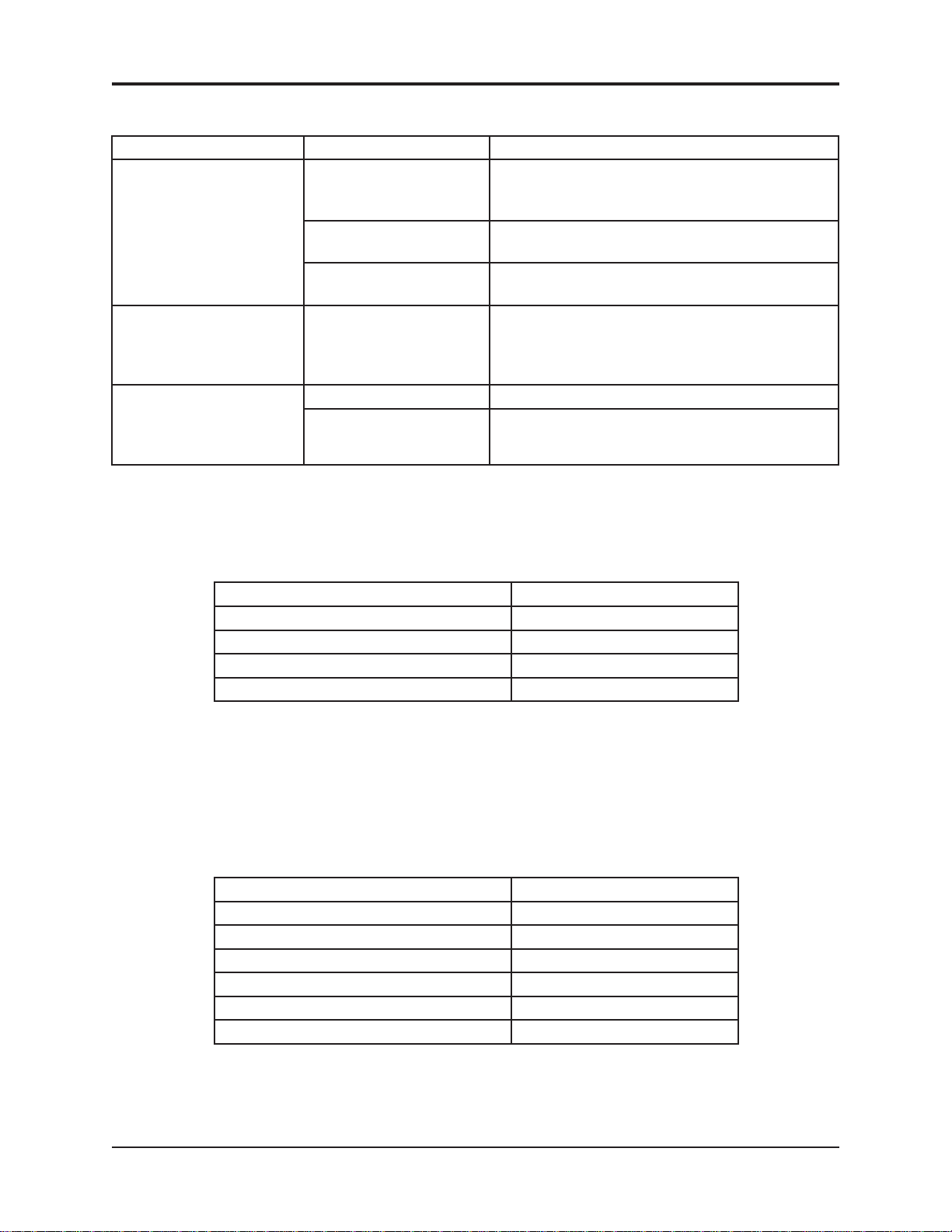
Blocked Fluid Passage In Diaphagm Pump
If the pump sounds like it is working but liquid does not flow,
clear the fluid passage as follows:
• Remove suction tube from the pail and blow air at 85 PSI
into the INLET Liquid Hose (see diagram). Step on foot
pedal to activate pump. This procedure may have to be
repeated several times. If this procedure does not help,
blow some water into the suction hose using a spray gun,
wait one minute and step on foot pedal to activate pump.
This procedure may have to be repeated several times. If
this procedure does not work, the pump must be replaced.
If you need to replace the pump call your local dealer.
The warranty on the diaphragm pump is two years from date of
purchase.
This procedure will also clear a blockage in the fluid line for the
brush. Follow the same procedure to clear a blockage in the
automatic nozzle except turn the timer instead of stepping on the foot pedal.
PROCEDURE 2
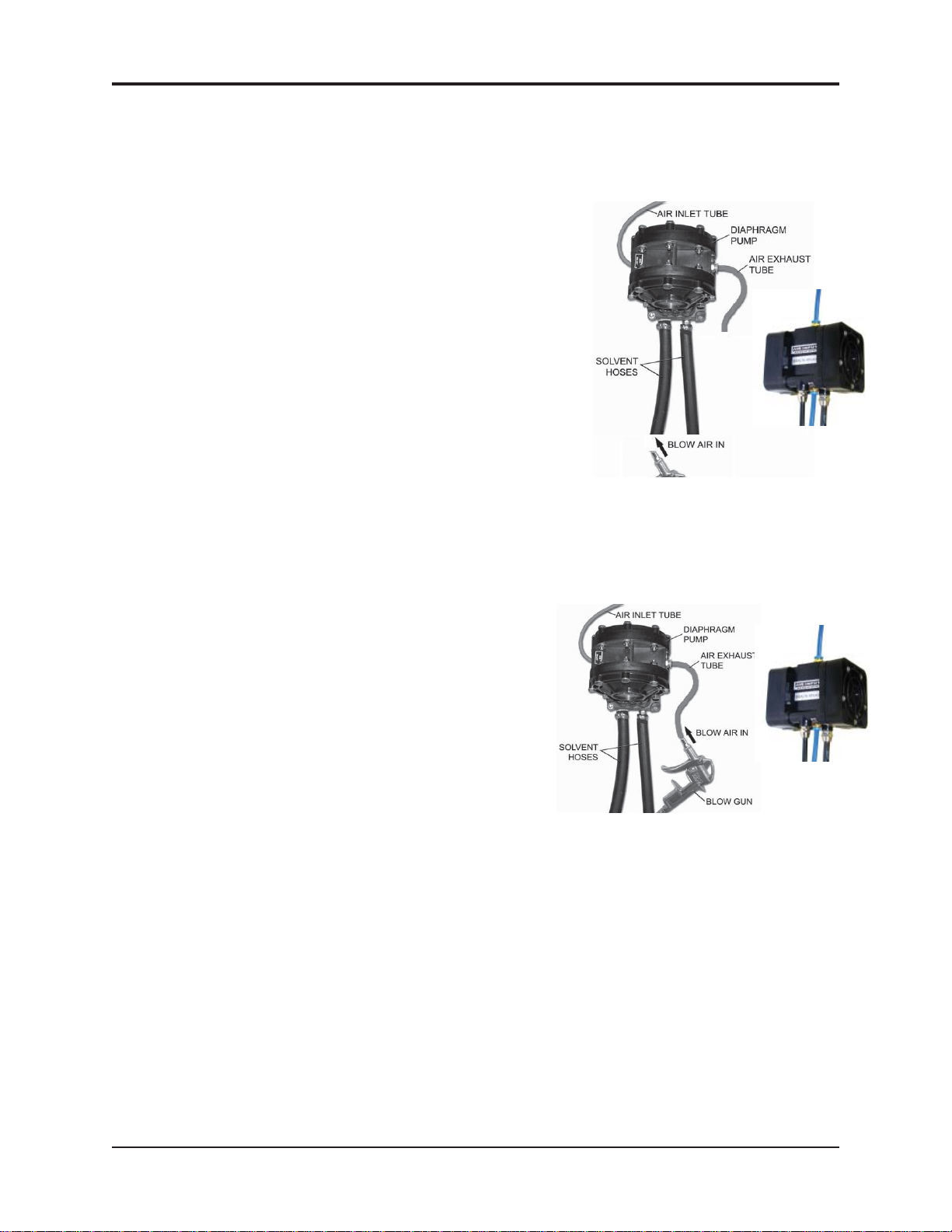
Blocked Air Passage In Diaphragm Pump
If there is a steady hissing sound and the pump is not
cycling, the spool valve has stalled due to a blocked air
passage. Follow the procedure below to clear the blockage.
• Connect a blow gun to an 85 PSI source. Locate the
blue hose that extends from the air exhaust port of
the diaphragm pump. Use a blow gun to blow air into
the open end of this hose. Turn timer. If the procedure
is successful, the pump will start working. The proce-
dure may have to be repeated several times. If this
procedure does not work, replace the pump.
• Cause: Contaminants in the air supply (water, oil,
solid particles etc)
• Preventative Action: If necessary, install an Airline
(Moisture) Filter.
PROCEDURE 3
Blocked Passage in Air Line
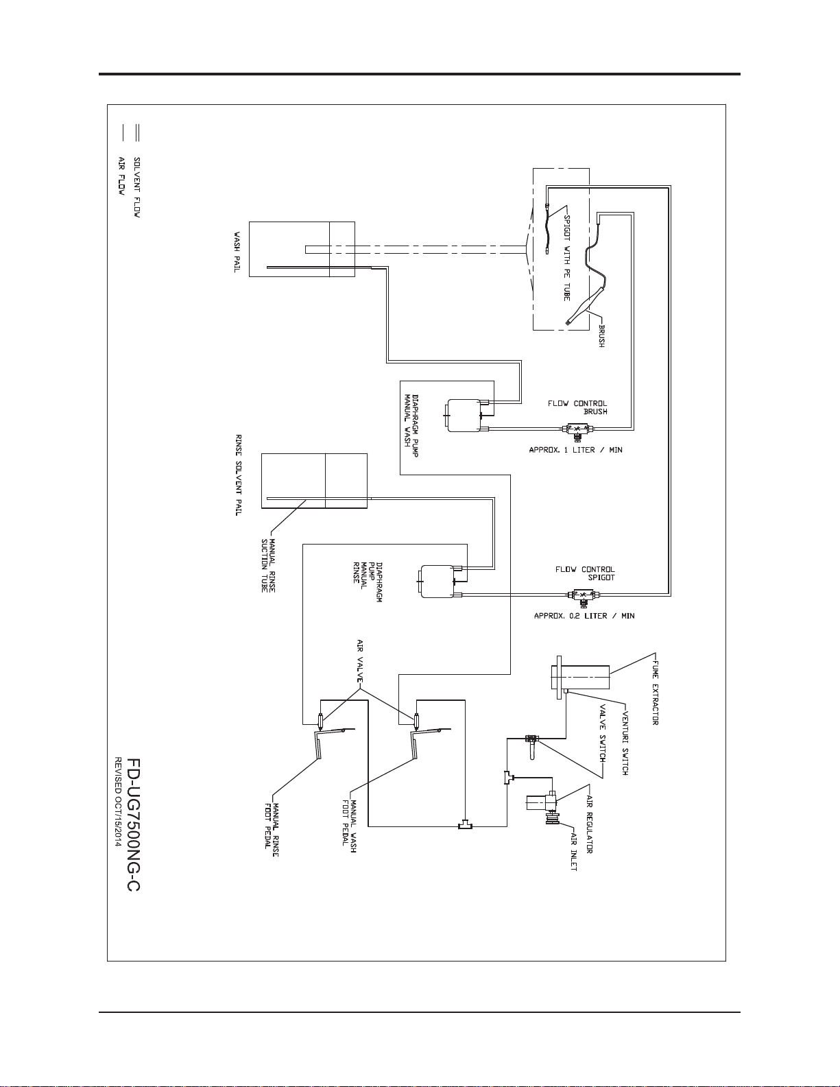
The components in the air line are the diaphragm pump, air valve, foot pedal, 3-way ball valve
and regulator. See the Flow Diagram and the section: Replacement Parts.
To troubleshoot a component:
1) Disconnect the air line to the component using the quick disconnect.
2) Step on foot pedal and check for presence of positive air pressure in the air line. If there is ample
positive air pressure, replace the component.
If air pressure is absent, there is a faulty component upstream. Reconnect the air line and check the
operation of the next component upstream by following steps 1 and 2 above.

8
MANUAL - UG7500NG SERIES WORK STATION REVISED 2013-01
Full Product Warranty
These Uni-ram products have been engineered and manufactured to high performance standards.
Each unit has been subjected to detailed factory testing before shipment.
This product comes with a one-year full warranty from the date of purchase. Uni-ram Corporation
reserves the right to repair or replace the unit, free of charge, to the original purchaser if a part is found
to be defective in material or workmanship as determined by factory service personnel. The items
listed below under "Conditions of Warranty" as consumables are not covered.
Uni-ram reserves the right to direct the customer to ship the unit collect to the Uni-ram factory or to an
approved Service Center for repair using the Uni-ram Return Goods Procedure or to repair the unit on-
site. To prevent damage in transport, the purchaser must ship the unit in the original packaging or use
alternate adequate packaging. All units must be shipped clean and free of liquid.
Diaphragm Pump:
We are pleased to advise that the warranty on the diaphragm pump, the heart of the spray gun
cleaner, comes with a 2 year replacement warranty. If, in the unlikely event your diaphragm pump fails
during the first two years of service, call Uni-ram Service at 1-800-417-9133. We will send you a new
pump free of charge and arrange for the return of your original pump.
Conditions of Warranty:
As Uni-ram Corporation has no control over the working conditions or circumstances under which the
purchaser stores, handles or uses the product, Uni-ram makes no warranty or claim, either expressed
or implied with respect to this product's fitness for any purpose or the result to be obtained from its
use. This condition applies to the sale of all products and no representative or distributor of Uni-ram
Corporation has the authority to waive or change these conditions.
This warranty applies only to the original purchaser and does not apply if the unit has been misused,
overloaded, neglected, altered or used for any purpose other than those specified in the operating and
installation instructions. Deterioration due to normal wear is not covered by this warranty. Damage due
to accident, transportation, fire, floods or acts of God is also not covered. Units whose serial numbers
have been altered or removed are not covered. The warranty is invalid if unauthorized chemicals as
noted in the manual or liquids with acid content are used in this unit. Unauthorized attempts at self-
repair or alterations by the owner also invalidate this warranty. Interior or exterior finishes are not cov-
ered by this warranty.
Consumable Items are not covered by this warranty (eg: gaskets, screens, bags, filters, nozzles and
air jets).
This warranty replaces all other warranties expressed or implied by statute or otherwise.
To make a claim, call Uni-ram Service at 1-800-417-9133 and quote the serial number of the unit.
This manual suits for next models
1
Table of contents
Other Uni-ram Cleaning Equipment manuals
Popular Cleaning Equipment manuals by other brands

Vax
Vax VMP8PU user guide

Vaportek
Vaportek Restorator 90-5000 Use and Operating Instructions

Braun
Braun 5434 quick start guide

Uzin Utz
Uzin Utz WOLFF RamHammer 169208 Translation of the original instruction

Nilfisk-Advance
Nilfisk-Advance Hybrid ECO SE11 Directions for use

Kärcher
Kärcher RBS 6000 Original instructions