Uniwell SX-6700F Operating instructions

SX-6600F
SX-6700F
SX-6750F
[SX6K]DRE-001
R
RE
EP
PA
AI
IR
R
M
MA
AN
NU
UA
AL
L
PRINT
INDEX
CAUTION

Caution Before Repairing
1. Please make sure that the AC cord plug is disconnected from the power
supply socket before repairing. Because some parts on the ECR are still in
the power-on condition even if the power switch is turned off or the control
key is turned to the OFF position,so the followings happen sometimes
when AC cord plug is connected:
1) If you touch some parts, you may have an electric shock.
2) If the board is removed, the board may be broken.
2. The batteries are installed on the MPU board so,do not put the removed
MPU boards on the conductive material (steel, etc.).
If the battery is shorted, all preset data is deleted and the board may be
broken depending on the case.
3. Many C-MOS LSI/ICs are used for the MPU board, display board, etc.
These ICs are sensitive about static electricity so they are easy to be
damaged. Before touching the MPU board, display board, etc, please
discharge static electricity ofyour hands first.
4. After repairing, please be sure to re-connect the ground wires where they
used to be. Otherwise, the noise proof cannot be effective.
5. Please be sure to do the initial reset operation after repairing.
6. Battery replacement
This machine has been equipped with the Nickel- Metal Hydride battery to
keep the contents of memories. At the time of battery replacement, it must
be replaced as follows.
Ni-MH BATTERY:
MODEL:
TYPE:
MANUFACTURER:
RATING:
GP80BVH3AMX
Nickel-Metal Hydride Battery
GPI International LTD.
3.6V,80mAH
CAUTION DANGER OF EXPLOSION IF BATTERY IS INCORRECTLY REPLACED. REPLACE ONLY WITH
THE SAME OR EQUIVALENT TYPE RECOMMENDED BY THE MANUFACTURER.
DISCARD USED BATTERIES ACCORDING TO THE MANUFACTURER'S INSTRUCTION.
ATTENTION DANGER D'EXPLOSION EN CAS DE REMPLACEMENT INCORRECT DE LA BATTERIE.
REMPLACER UNIQUEMENT PAR UNE BATTERIE DU MEME TYPE OU D'UN
TYPERECOMMANDE PAR LE CONSTRUCTEUR. METTRE AU REBUT LES BATTERIES USEES
CONFORMEMENT AUX INSTRUCTIONS DU FABRICANT.
VORSICHT EXPLOSIONGEFAHR, WENN BATTERIE FALSCH EINGESETZT WIRD. NUR DURCH
BATTERIE DESSELBEN ODER VOM HERSTELLER EMPFOHLENEN GLEICHWERTIGEN TYPS
ERSETZEN. GEBRAUHTE BATTERIEN NACH ANWEISUNG DES HERSTELLERS ENTSORGEN.
PRINT
INDEX

TABLE OF CONTENTS
I. GENERAL EXPLANATION
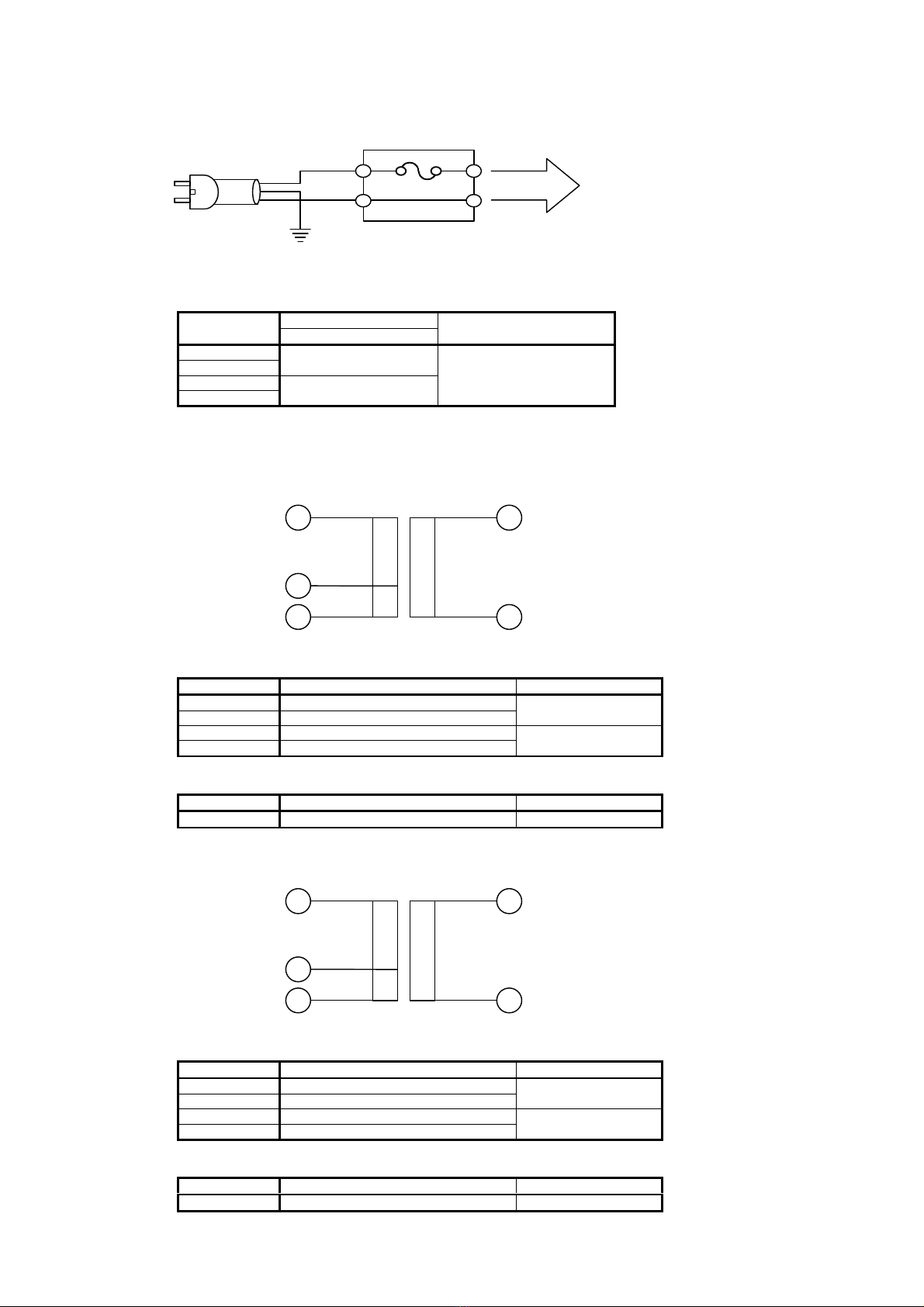
1. CONNECTION DIAGRAM OF SX-6600.................................................................................................1
2. CONNECTION DIAGRAM OF SX-6700.................................................................................................2
3. CONNECTION DIAGRAM OF SX-6750.................................................................................................3
II. EXPLANATION OF BLOCKS
1. PRIMARY POWER BLOCK CIRCUIT.....................................................................................................1
1-1. Fuse...............................................................................................................................................................1
1-2. Transformer..................................................................................................................................................1
1-2-1. SX-6600....................................................................................................................................................................1
1-2-2. SX-6700/6750...........................................................................................................................................................1
2. SECONDARY POWER BLOCK CIRCUIT................................................................................................2
2-1. Block Diagram of Power Block Circuit .......................................................................................................2
2-2. Description of Voltage ..................................................................................................................................2
2-3. Secondary Fuse.............................................................................................................................................2
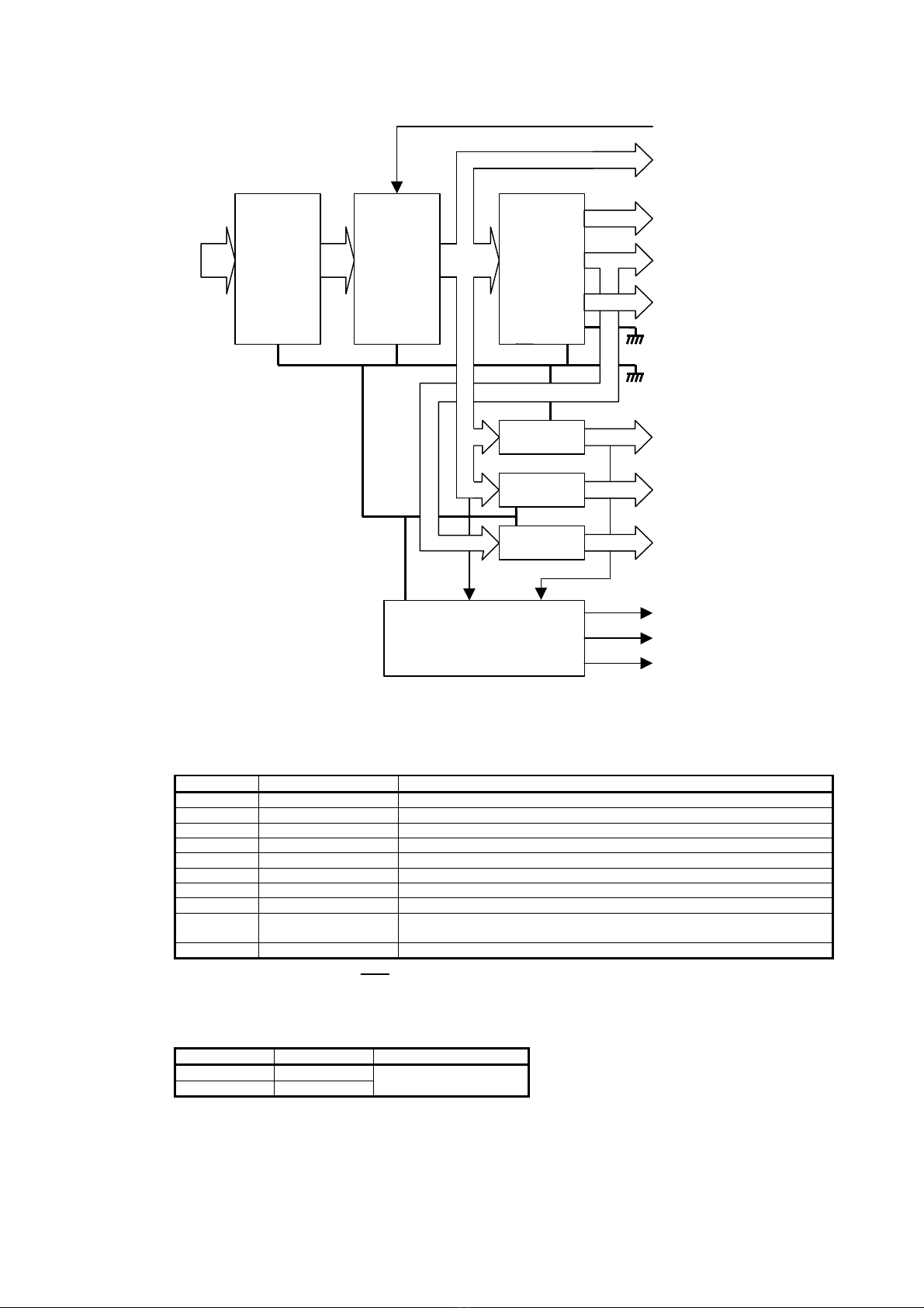
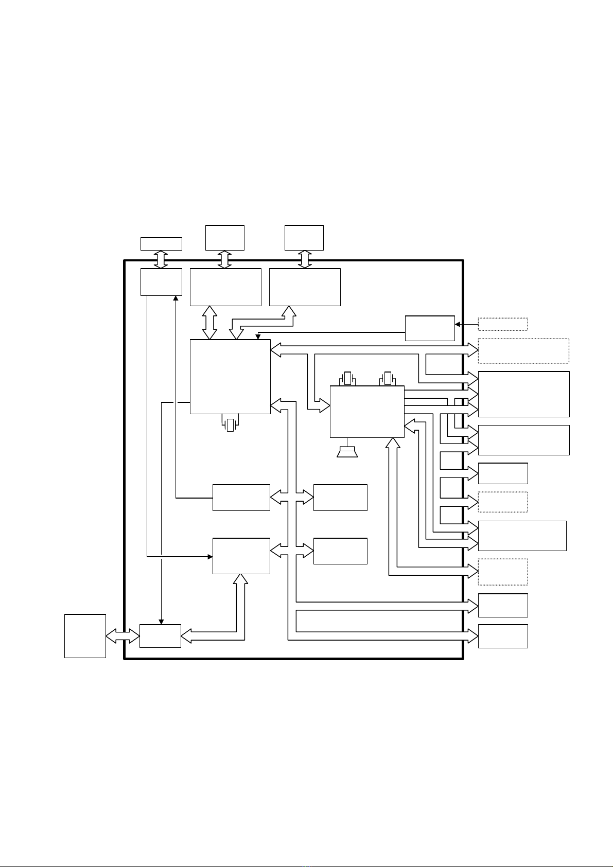
3. LOGIC BLOCK CIRCUIT .....................................................................................................................3
3-1. Logic Block Diagram of MPU UNIT 071-1 (SX-6600)................................................................................3
3-2. Logic Block Diagram of MPU UNIT 071-2 (SX-6700/6750).......................................................................4
3-3. Block Diagram of PRT UNIT 041 (SX-6750)..............................................................................................5
3-4. Block Diagram of PRT UNIT 051 (SX-6700/6750).....................................................................................5
3-5. Block Diagram of DSP UNIT 061................................................................................................................5
4. TERMINAL LIST OF PRINTER.............................................................................................................6
4-1. M-U420 for SX-6600.....................................................................................................................................6
4-1-1. Connector Pin Arrangement...................................................................................................................................6
4-1-2. Connector Pin Assignments....................................................................................................................................6
4-2. M-T245 for SX-6700.....................................................................................................................................7
4-2-1. Connector Pin Arrangement...................................................................................................................................7
4-2-2. Connector Pin Assignments....................................................................................................................................7
4-2-3. Connector of Paper Feed Motor..............................................................................................................................7
4-3. LT-1320 for SX-6750.....................................................................................................................................8
4-3-1. Connector Pin Arrangement...................................................................................................................................8
4-3-2. Connector Pin Assignments....................................................................................................................................8
4-3-3. Connector Pin Assignment of Paper Feed Motor...................................................................................................8
4-3-4. Connector Pin Assignment of Sensor .....................................................................................................................8
III. ILLUSTRATION OF ECR ASSEMBLY & MACHINE PARTS LIST
1. SX-6600F
1-1. SX-6600F Illustration of ECR assembly.....................................................................................................1
1-2. SX-6600F Parts List.....................................................................................................................................2
2. SX-6700F
2-1. SX-6700F Illustration of ECR assembly.....................................................................................................1
2-2. SX-6700F Parts List.....................................................................................................................................2
3. SX-6750F
3-1. SX-6750F Illustration of ECR assembly.....................................................................................................1
3-2. SX-6750F Parts List.....................................................................................................................................2
IV. UNIT PARTS LIST
1. MPU UNIT........................................................................................................................................1
1-1. MPU UNIT 071-1.........................................................................................................................................1
1-2. MPU UNIT 071-2.........................................................................................................................................5
2. PRINTER CONTROLLER UNIT............................................................................................................8
2-1. PRT UNIT 041..............................................................................................................................................8
2-2. PRT UNIT 051..............................................................................................................................................9
3. DISPLAY UNIT.................................................................................................................................10
3-1. DSP UNIT 061............................................................................................................................................10
3-2. SX7000 REAR DISPLAY UNIT.................................................................................................................10
PRINT

V. RECOMMENDED PARTS LIST
1. MACHINE
1-1. SX-6600F.......................................................................................................................................................1
1-2. SX-6700F.......................................................................................................................................................1
1-3. SX-6750F.......................................................................................................................................................1
VI. DRAWING LIST
Unit name Circuit name Description Drawing # Control # Page
PRIMARY FUSE CIRCUIT
FUSE PWB FUSE CIRCUIT FU021-A E-FU-01 940821 1/1
POWER / MPU BLOCK CIRCUIT
BLOCK 010413 1/8
POWER 010413 2/8
MPU 010413 3/8
MEMORY 010413 4/8
IO 010413 5/8
PRT 010413 6/8
SERIAL 010413 7/8
MPU UNIT 071-1/2
KEYCNTL
MPU071-C
010413 8/8
PRT CTL CIRCUIT
PRT UNIT 041 1P I/F PRT041-B 010417 1/1
BLOCK 010413 1/3
PRT.CNT 010413 2/3
PRT UNIT 051
DRIVER
PRT051-C
010413 3/3
DISPLAY CIRCUIT
DSP UNIT 061 DISPLAY DSP061-A 010130 1/1
SX7000 REAR DISPLAY UNIT BACK DISPLAY CIRCUIT DSP011-A E-UN10-05 930727 1/1
KEYBOARD UNIT CIRCUIT
FLAT KEYBOARD 991014 1/1
PRINT

General Explanation - 1
I. GENERAL EXPLANATION
1. Connection Diagram of SX-6600
: OPTION
MPU UNIT 071-1
ROM
CN28
BATTERY
FUSE
PWB
CN1
TRANS
FORMER
F
CN4
CH-A
(RS485)
RJ-45
CN5
CH-B
(RS232C)
DSUB-9P
Drawer1
RJ-11
CN2
CN3
Drawer2
RJ-11
CLERK
INSERT KEY
CN21
CN20
IBUTTON
I F UNIT 071
CN1
CN2
CN3
CN15
MR UNIT 021
CN18
CN1
CARD READER
CN19
SX7000
FLAT KEYBOARD
CN16
CN17
CN7
SW
CN26
CN25
M-U420
CN9
CN10
DSP UNIT 061
SX7000 REAR
DISPLAY UNIT
CN8
CN11
CN1
CN2
CN12
CN13
CN1
CN2
CN3
CONTROL
KEY
CN14
RT UNIT
101
(RS232C)
DSUB-9P RT UNIT
101
(RS232C)
DSUB-9P
CH-D CH-E
DOT REAR
DISPLAY UNIT
JNE
PRINT
INDEX

General Explanation - 2
2. Connection Diagram of SX-6700
: OPTION
MPU UNIT 071-2
ROM
CN28
BATTERY
FUSE
PWB
CN1
TRANS
FORMER
F
CN4
CH-A
(RS485)
RJ-45
CN5
CH-B
(RS232C)
DSUB-9P
Drawer1
RJ-11
CN2
CN3
Drawer2
RJ-11
CLERK
INSERT KEY
CN21
CN20
IBUTTON
I F UNIT 071
CN1
CN2
CN3
CN15
MR UNIT 021
CN18
CN1
CARD READER
CN19
SX7000
FLAT KEYBOARD
CN16
CN17
CN7
SW
M-T245
CN9
CN10
DSP UNIT 061
SX7000 REAR
DISPLAY UNIT
CN8
CN11
CN1
CN2
CN12
CN13
CN1
CN2
CN3
CONTROL
KEY
CN14
RT UNIT
101
(RS232C)
DSUB-9P RT UNIT
101
(RS232C)
DSUB-9P
CH-D CH-E
DOT REAR
DISPLAY UNIT
PRT UNIT 051
CN31
CN32
CN33
CN34
CN35
RFD
RNE
CUTTER
JNE
JFD
HEAD
CN39
CN40
CN24
CN41
CN30
PRINT
INDEX

General Explanation - 3
3. Connection Diagram of SX-6750
: OPTION
MPU UNIT 071-2
ROM
CN28
BATTERY
FUSE
PWB
CN1
TRANS
FORMER
F
CN4
CH-A
(RS485)
RJ-45
CN5
CH-B
(RS232C)
DSUB-9P
Drawer1
RJ-11
CN2
CN3
Drawer2
RJ-11
CLERK
INSERT KEY
CN21
CN20
IBUTTON
I F UNIT 071
CN1
CN2
CN3
CN15
MR UNIT 021
CN18
CN1
CARD READER
CN19
SX7000
FLAT KEYBOARD
CN16
CN17
CN7
SW
LT-1320
CN9
CN10
DSP UNIT 061
SX7000 REAR
DISPLAY UNIT
CN8
CN11
CN1
CN2
CN12
CN13
CN1
CN2
CN3
CONTROL
KEY
CN14
RT UNIT
101
(RS232C)
DSUB-9P RT UNIT
101
(RS232C)
DSUB-9P
CH-D CH-E
DOT REAR
DISPLAY UNIT
PRT UNIT 051
CN36
CN38
CUTTER
HEAD
CN37
CN40
CN24
CN41
CN30
PRT UNIT041
CN1
CN5
CN3
PRINT
INDEX

Explanation of Blocks - 1
II. EXPLANATION OF BLOCKS
1. Primary Power Block Circuit
1-1. Fuse
(Table 1. Primary Fuse Specification)
Rating
Working
AC Voltage SX-6600/6700/6750 Remark
100V
120V 250V 1A
220V
240V 250V 0.5A Slow blow type
1-2. Transformer
1-2-1. SX-6600
(Table 2. Primary Tap Specification)
Input voltage Wire color, Tap No. Transformer
100V Black (1) –Gray (2)
120V Black (1) –White (3) TUSX7HUL
220V Black (1) –Brawn (2)
240V Black (1) –Yellow (3) TUSX7HEB
(Table 3. Secondary Tap Specification)
Symbol Wire color, Tap No. Voltage (Non Load)
VP tap Orange (4) –Yellow (5) AC 24V
1-2-2. SX-6700/6750
(Table 4. Primary Tap Specification)
Input voltage Wire color, Tap No. Transformer
100V Black (1) –Gray (2)
120V Black (1) –White (3) TUSX7KUL2
220V Black (1) –Brawn (2)
240V Black (1) –Yellow (3) TUSX7KEB2
(Table 5. Secondary Tap Specification)
Symbol Wire color, Tap No. Voltage (Non Load)
VP tap Orange (4) –Yellow (5) AC 24V
Power
Transformer
FUSE
FUSE PWB
(Primary Power Block Circuit)
Yellow
1
2
3
5
4
Primary Secondary
Orange
VP tap
(Power Transformer)
Yellow
1
2
3
5
4
Primary Secondary
Orange
VP tap
(Power Transformer)
PRINT
INDEX

Explanation of Blocks - 2
2. Secondary Power Block Circuit
2-1. Block Diagram of Power Block Circuit
2-2. Description of Voltage
The following voltages are generated by the power circuit and are used for the logic circuit
(Table 6)
Symbol Voltage Remark
VP DC 25V For driving printer, drawer
VLL DC 11.4V~12.6V For RS232C
VMM DC –11.5V~ –12.5V For RS232C
VCC DC 5V For LSI’s logic circuit
VBT DC 5V / 3.6 ~ 4.2V For memory back up
VBB DC –25V For driving display tube
VF AC 4.0V ~ 4.5V For heater of display tube
NMIIN# DC 5V / 0V Power level monitor signal 5V : normal power 0V : power failure
RES# DC 5V / 0V Reset signal for every LSI, and also the positive going edge of this signal is
the start up signal for the CPU
RAME DC 5V / 0V To be controlled by RES# signal, and to be used for protection of memory data
(meaning of “#”: ex.RES# = RES)
2-3. Secondary Fuse
(Table 7)
Parts Number Rating Remark
F1 125V 3A
F2 125V 2A Normal Blow Type
Transformer
Secondary
Tap
VP
DC-DC
Converter
Rectification
Circuit Voltage
Regulator
VF
VBB
VBT
L.GND
P.GND
P-OFF
VMM
VCC
Power on/off detection circuit
NMIIN#
RES#
RAME
VLL
Voltage
Regulator
Voltage
Regulator
Switching
Regulator
PRINT
INDEX

Explanation of Blocks - 3
3. Logic Block Circuit
3-1. Logic Block Diagram of MPU UNIT 071-1 (SX-6600)
As shown in the figure below, the logic block is composed of the following components:
-TMP95C265F CPU : the core which controls all machine circuitry and controls serial I/O
-4M EP-ROM (512k x 8bit) : which contains the application program
-4M CMOS RAM (512k x 8bit) : which memorizes the processed data
-D75206GF-740 Key/Display Controller : which controls Key, Display, Keyboard, Clerk Insert Key, Card Reader
-UPD71055 : which controls the Drawer sensor, Printer
MPU UNIT 071-1
DOT REAR
DISPLAY UNIT
Port
74HC273
Driver
Sensor
Drawer
I Button
Interface
I Button
2nd I/F
Board
EXT RAM
Board
ROM
512K x 8bit
RAM
512K x 8bit
CH-B
D-SUB
RS232C
Driver/Receiver
MC145406F
CH-A
D-SUB
RS485
Driver/Receiver
SN751178NS
16bit CPU
TMP95C265F
24.576MHz
XTAL1
32.768MHz
XTAL3
4.91MHz
XTAL2
Buzzer
Card
Reader
SX-7000
FLAT KEYBOARD
SX-7000 REAR
DISPLAY UNIT
Control
Key
Clerk
Insert Key
Driver
Sensor
DSP UNIT 061
Clocked Serial I/O
Digit line
Segment line
Scan line
Return line
Key / Display
Controller
D75206GF-740
A
d
d
r
e
s
s
/
D
a
t
a
L
i
n
e
Parallel Port
Interface
UPD71055
Printer
M-U420
PRINT
INDEX

Explanation of Blocks - 4
3-2. Logic Block Diagram of MPU UNIT 071-2 (SX-6700/6750)
As shown in the figure below, the logic block is composed of the following components:
-TMP95C265F CPU : the core which controls all machine circuitry and controls serial I/O
-4M EP-ROM (512k x 8bit) : which contains the application program
-4M CMOS RAM (512k x 8bit) : which memorizes the processed data
-D75206GF-740 Key/Display Controller : which controls Key, Display, Keyboard, Clerk Insert Key, Card Reader
-UPD71055 : which controls the Drawer sensor
MPU UNIT 071-2
DOT REAR
DISPLAY UNIT
Port
74HC273
Driver
Sensor
Drawer
I Button
Interface
I Button
2nd I/F
Board
EXT RAM
Board
ROM
512K x 8bit
RAM
512K x 8bit
CH-B
D-SUB
RS232C
Driver/Receiver
MC145406F
CH-A
D-SUB
RS485
Driver/Receiver
SN751178NS
16bit CPU
TMP95C265F
24.576MHz
XTAL1
32.768MHz
XTAL3
4.91MHz
XTAL2
Buzzer
Card
Reader
SX-7000
FLAT KEYBOARD
SX-7000 REAR
DISPLAY UNIT
Control
Key
Clerk
Insert Key
Serial
Interface
M66230FP
DSP UNIT 061
Clocked Serial I/O
Digit line
Segment line
Scan line
Return line
Key / Display
Controller
D75206GF-740
A
d
d
r
e
s
s
/
D
a
t
a
L
i
n
e
Parallel Port
Interface
UPD71055
PRT
UNIT
051
PRINT
INDEX

Explanation of Blocks - 5
3-3. Block Diagram of PRT UNIT 041 (SX-6750)
3-4. Block Diagram of PRT UNIT 051 (SX-6700/6750)
-TMP95FY64 Printer Controller : which controls printer
-1M CMOS RAM (128k x 8bit) : which memorizes the print data
3-5. Block Diagram of DSP UNIT 061
PRT UNIT 041
Printer
LT-1320 PRT UNIT 051
Sensor
Driver
PRT UNIT 041
Printer
LT-1320
RAM
128K x 8bit
Printer Controller
TMP95FY64
Printer
M-T245
24.576MHz
XTAL4
*1
*1
Head
Paper
Sensor
*1
Serial
Data
Buffer
Auto Cutter
Driver/Sensor
*1
Driver
*2
*2
*2
MPU UNIT 071-2
*2
PRT UNIT 051
*1: SX-6700
*2: SX-6750
Dot VFD Controller
M66004FP
/RESDSP/CS
Front Dot Display
(DL1619A)
16 digits
RDSPON
(Rear Display
ON/OFF)
/RESET/CS P0
Front Display
(FIP12C12)
12 digits
Digit
line Segment
line
CN3
CN2
CN1
MPU UNIT 071-2
PRINT
INDEX

Explanation of Blocks - 6
4. Terminal List of Printer
4-1. M-U420 for SX-6600
4-1-1. Connector Pin Arrangement
4-1-2. Connector Pin Assignments
Main motor (-) 1
+24................................................................................... 2
Print solenoid #3.............................................................. 3
Receipt feed trigger electromagnet ................................. 4
Print solenoid #1.............................................................. 5
Journal feed trigger electromagnet................................... 6
Print solenoid #7.............................................................. 7
Stamp trigger electromagnet............................................ 8
Print solenoid #5.............................................................. 9
Cutter motor (-) (selected function)................................. 10
Print solenoid, 24V common line .................................... 11
Print solenoid, 24V common line .................................... 12
Print solenoid #9.............................................................. 13
Print solenoid, 24V common line .................................... 14
Print solenoid #8.............................................................. 15
Cutter motor (+) (selected function)................................ 16
Print solenoid #6.............................................................. 17
[Empty]............................................................................ 18
Print solenoid #4.............................................................. 19
[Empty]............................................................................ 20
Print solenoid #2.............................................................. 21
[Empty]............................................................................ 22
Frame ground (FG).......................................................... 23
Frame ground (FG).......................................................... 24
Thermosensitive resistance element ................................ 25
5V GND........................................................................... 26
Thermosensitive resistance element ................................ 27
Timing-detector waveform.............................................. 28
+5V.................................................................................. 29
Validation detector waveform (option)............................ 30
Reset detector waveform ................................................. 31
Option.............................................................................. 32
Option.............................................................................. 33
Cutter reset detector waveform (selected function)......... 34
1
2
33
34
Connection Terminal Assignments
(As viewed when facing the connectors)
M
M
FG
PRINT
INDEX

Explanation of Blocks - 7
4-2. M-T245 for SX-6700
4-2-1. Connector Pin Arrangement
4-2-2. Connector Pin Assignments
(Table 8)
Pin No. Circuit Pin No. Circuit Pin No. Circuit
1VH2VH3VH
4GND 5GND 6GND
7DI 8DO 9CLOCK
10 GND 11 LATCH 12 GND
13 STROBE5 14 VDD 15 STROBE3
16 STROBE4 17 STROBE1 18 STROBE2
19 TH 20 TH 21 GND
22 GND 23 GND 24 VH
25 VH26 VH27 Paper end detector - GND
28 Receipt paper end signal 29 Journal paper end signal 30 Paper end detector - VCC
31 Head up detector - VCC 32 Head up detector - GND
4-2-3. Connector of Paper Feed Motor
321
Feeding
direction
6
4
2
5
3
1
Phase B Phase ACOM
COM
Phase C
Phase D
Motor
(Connection diagram)
1
2
3
4
5
6
(Pin No.)
PRINT
INDEX

Explanation of Blocks - 8
4-3. LT-1320 for SX-6750
4-3-1. Connector Pin Arrangement
4-3-2. Connector Pin Assignments
(Table 9)
Pin No. Circuit Pin No. Circuit Pin No. Circuit
1HEDCOM 11 PGND 21 VDD
2HEDCOM 12 PGND 22 STRB4#
3HEDCOM 13 PGND 23 STRB3#
4HEDCOM 14 PGND 24 SDI
5SDO 15 PGND 25 HEDCOM
6SCLK 16 PGND 26 HEDCOM
7LATCH# 17 PGND 27 HEDCOM
8STRB2# 18 PGND 28 HEDCOM
9STRB1# 19 PGND
10 TH 20 TH
4-3-3. Connector Pin Assignment of Paper Feed Motor
4-3-4. Connector Pin Assignment of Sensor
4
2
3
1
A A
B
B
Motor
(Connection diagram)
1Pin 28Pin
1
4
2
3
5
7
Paper Sensor
Head up Sensor
PTE
PTC
PDA
PDK
HUPS
HDA
(Connection diagram)
6
HUPG
PRINT
INDEX

III. ILLUSTRATION OF ECR ASSEMBLY &MACHINE PARTS LIST
PRINT
INDEX

SX-6600F - 1
1. SX-6600F
1-1. SX-6600F Illustration of ECR assembly
PRINT
INDEX

SX-6600F - 2
1-2. SX-6600F Parts List
SX-6600F Parts List - 1/2
NUMBER
REF.#
PARTS NAME
Q'TY
Used for
1- 1 38284 POWER CHASSIS SX7000 1
15044 TUSX7HEB E,BS,A,B,P
1- 2 15045 TUSX7HUL 1N,C
1- 3 34013 INSU LOCK TIE T18R 2
1- 4 34135 CLAMP CS-6 2
1001AC CORD AUSTRALIA A
1005AC CORD USA HANAI P,N,C
1006 AC CORD CEE OPE-2 E,B
1- 5
1011 AC CORD UK
1
BS
1- 6 33157 TERMINAL LRA-51T-4 1
1- 7 34047 AC CORD CLAMPER KR-51 1
1- 8 34165 RING CORE TR-25-15-12 1
1- 9 3171 FUSE PWB FU021-A 1
34221 FUSE(UL/CSA) K19374/1A N,C
®
1-10 34223 FUSE(SEMKO) K19372/500mA 1E,BS,A,B,P
®
1-11 34048 LOCKING SPACER KGLS-4S 2
35140 FUSE LABEL T1A/250V N,C
1-12 35182 FUSE LABEL 250V 0.5AT 1E,BS,A,B,P
2- 1 36301 LOWER CASE SX7000 1
2- 2 39032 RUBBER SHEET S15 5
2- 3 30004 1801R/1-0143 1
2- 4 16292 WH-316 1
2- 5 38285 IF BRACKET SX7000 1
2- 6 38276 LAN COVER 1
2- 7 38243 COVER PLATE UX-50 1
2- 8 38287 BOTTOM PLATE SX7000 1
2- 9 36302 CARD READER COVER SX7000 1not required when card reader is installed
2-10 40573 MPU UNIT 071-1 1
®
2-11 24152 M27C4001-10F1 1
®
2-12 35141 ROM SEAL 1
2-14 34279 LOCKING SPACER KGTS-4K 1
40526 M-U420-081 WITH RIBBON auto cutter printer
®
3- 1 40532 M-U420-091 WITH RIBBON 1manual cutter printer
®
3- 2 36280 PAPER GUIDE FRAME SX-330 1
3- 3 36089 ROLLER 2
3- 4 16328 WH-350 1
3- 5 16388 WH-414 1
3- 6 16370 WH-394 1
3- 7 39003 PRINTER CUSHION 4
3- 8 33086 PIPE 3X 4X 8L 4
3- 9 34135 CLAMP CS-6 1
4- 1 38288 FLAT KEY CHASSIS SX7000 1
4- 2 40559 SX7000 FLAT KEYBOARD 1
4- 4 28037 CTL-LOCK GSK-3S 1
4- 5 16351 WH-375 1
4- 6 16370 WH-394 1
5- 1 36303 PRINTER COVER SX7000 1
5- 2 36304 JOURNAL WINDOW SX7000 1
5- 3 36306 VALIDATION COVER SX7000 1
5- 4 39057 CAM LOCK DA80D-22 1
6- 1 36307 REMOTE COVER SX7000 1
6- 2 40552 SX7000 REAR DISPLAY UNIT 1
®
6- 3 36308 REMOTE MASK SX7000 1
7- 1 36310 LCD CASE SX7000 B 1
7- 2 41221 BRACKET(L) ASS'Y SX 1
7- 4 41222 BRACKET(R) ASS'Y SX 1
7- 8 40576 DSP UNIT 061 1
®
7-13 36319 LCD CASE F ASS'Y (SMOKE) 1
8- 1 36309 UPPER CASE SX7000 1
8- 3 35321 NAME PLATE UX-70 1
8- 4 35381 CONTROL LABEL SX7000 1
8- 5 38291 UPPER CASE BRACKET SX7000 1
8- 6 34135 CLAMP CS-6 3
8- 7 34013 INSU LOCK TIE T18R 2
8- 8 16029 WH-030 2
PRINT
INDEX

SX-6600F - 3
SX-6600F Parts List - 2/2
NUMBER
REF.#
PARTS NAME
Q'TY
Used for
9- 1 34165 RING CORE TR-25-15-12 1
9- 2 34135 CLAMP CS-6 2
9- 3 36313 IF COVER SX7000 1
9- 5 35384 IF LABEL SX7000 1
11- 1 36292 REMOTE PIPE TX850 F 1
11- 2 36293 REMOTE PIPE TX850 B 1
11- 3 36288 WEDGE PLATE TX850 1
11- 4 34108 PAPER ROLL FOR M45 2
11- 5 16029 WH-030 1
11- 6 16347 WH-373 1
11- 7 28038 CONTROL KEY GSK-3S-2A 1
11- 8 39192 WATER PROOF COVER SX7000F 1
11- 9 35394 FLAT KEY SHEET SX6000 1
11-10 35*** MANUAL 1
NW2 33060 M3TW,UC *
SC1 33011 P(M3X6)SP *
SC2 33021 P(M4X6)S *
SC3 33229 P(M4X8)SP,NI *
SC4 33183 T(M4X8)NI *
TS 2 33220 T2B(2.6X6) *
TS 3 33031 T2B(2.6X8) *
TS 4 33035 T2B(3X8) *
TS 5 33036 T2B(3X10) *
TS 6 33191 T2B(3X10)UC *
TS 8 33228 T2B(3X14)UC *
TS 9 33227 T2B(4X10) *
TS10 33044 T2B(4X12) *
TS11 33223 T3B(2X6) *
TS12 33206 T3B(2.6X5) *
TS13 33046 T3B(3X6) *
TS14 33048 T3B(4X6) *
TS16 33232 T2W(3X16) *
TS17 33233 T2F(4X12) *
TU1 34154 SHRINK TUBE 3D *
E = 220V, for Europe C = CSA NRTL/C N = 120V, not approved for CSA NRTL/C
BS = 240V, AC cord is for U.K. B = 240V, AC cord is for Europe P = for Philippines A = Australia
® Spare quantities of the parts should be kept at all times. Refer to V.RECOMMENDED PARTS LIST for the necessary quantities.
* As quantity of Fastener, Washer, Tape... depends upon its optional things such as card reader,
clerk insert key...etc., please refer to the parts price list which is standard for your use (your market).
PRINT
INDEX

SX-6700F - 1
2. SX-6700F
2-1. SX-6700F Illustration of ECR assembly
PRINT
INDEX
This manual suits for next models
2
Table of contents
Other Uniwell Cash Register manuals

Uniwell
Uniwell PX-5700 User manual

Uniwell
Uniwell NX-5400 User manual

Uniwell
Uniwell CX-3500 User manual

Uniwell
Uniwell LX-5600 User manual

Uniwell
Uniwell UN-1360 User manual

Uniwell
Uniwell LX-5700 Operating instructions

Uniwell
Uniwell SX-330 User manual

Uniwell
Uniwell SX-6600 User manual

Uniwell
Uniwell SX-6600F User manual

Uniwell
Uniwell SX-7005 User manual