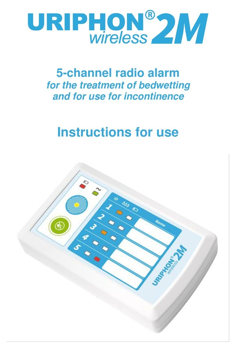
URIPHON wireless 2 User manual

1
Wireless alarm device for the monitoring of
bedwetting(enuresis)
Instructions for use

2

3
E
Alarm device for the treatment of bedwetting
Description:
The new device is the successor model to the Uriphon® wireless,
which was produced as a ‘paired’ (transmitter and receiver). This meant that in
the past transmitter and receiver could only communicate if both components
were manufactured and delivered with the same radio channel. With the
this has now completely changed. The transmitter and receiver’s
factory settings now allow them to work independently. Each transmitter has a
unique identification code and is paired, during its initial start-up, with the
receiving unit.
The main advantage to this lies in the fact that in the event of a potential
malfunction of one of the two components, these can be replaced individually
now rather than a complete pair being required. In addition, any
transmitter can be paired with any receiver.
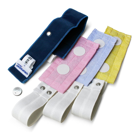
Absorbent pads which are fastened to underwear in use are available for the new
version too. They can be used freely in any underwear and also offer continuous use
without a drying phase. They can be re-inserted immediately after an alarm. It is not
necessary to use special underpants.
Thanks to the new mobile, even smaller and more convenient transmitter, the
product is now significantly more flexible, offering increased sleeping comfort
and freedom of movement. Additionally the transmitter is equipped with a
switchable vibration alarm.
Note: can also be used with a bed liner. (see section "Additional Options")
The unique identification code of the transmitter allows the use of multiple devices
within a common environment without interference. The radio range within buildings is
between 15 and 30 metres. This makes ideal for hospital use too.

4
Delivered with:
Receiver, Transmitter, 3 absorbent pads with adhesive points, 2 AA type batteries
(for the Receiver). 1 CR2450 button battery (for the Transmitter), power supply unit,
storage bag, detailed manual, brochure "Bedwetting - the latest information for a
common problem."
Fig. 1: Outer packaging, Device serial numbers
Receiver serial number
Transmitter serial number

5
Delivery of :
Fig. 2: Delivery
Instructions for use
3 contact pads
with spare adhesive points
Power Supply
unit
Transmitter
Receiver
Button battery CR2450
2 type AA batteries

6
Components - Functions and function indicators - Controls:
Transmitter
Fig. 3: Transmitter, front
Clips to attach the Transmitter
to the underpants
Press studs to fix
the contact-pads
„Pairing Button“
Serial number of the Transmitter

7
Fig. 4: Transmitter, back
Receiver
Fig. 5: Receiver, front
Important note:
All the important functions of the appear exclusively on the receiver.
It is recommended that the batteries are installed when operating with the power
supply. This means that the device will continue to work continuously e.g. during a
power outage. The batteries will only be used when operating without a power supply
feed.
Depending on the number of alarms triggered and on the respective alarm duration,
the capacity of the batteries extends for several months.
LED display for the operating mode of the
Receiver:
No display: The device is running on battery
and the battery is charged
Red LED flashes: The Receiver batteries
have to be replaced
Green LED: Device running on power supply
Beeper
Label, e.g.
for name or room number
LED indicators for the
Transmitter and pairing mode:
Only orange coloured LED (drop
symbol) is lit: The alarm is triggered, the
sensor is wet
Only red LED (battery icon) flashing:
The battery of the Transmitter is weak
and must be replaced.
Both LEDs are lit: The device is in
pairing mode
Function button "alarm stop" and
“Pair transmitter”

8
Receiver
Fig. 6: Receiver, back with closed battery compartment
Fig. 7: Receiver, back with open battery compartment
Battery compartment
cover
Serial number of the Receiver
Battery compartment for two
1.5V AA batteries
Connection jack for operating the receiver
with mains supply 100-240V AC

9
Contact pads
Fig. 8: Contact pads
Power supply plug with cable
Fig. 9: Power supply plug with cable
Press studs for the connection of
the contact pads with the Transmitter
adhesive points for fixing the
contact pads to the underpants
Power supply plug for connection
to 100-240V AC
Plug to connect to the receiver
(power supply)

10
Starting the device:
Important note: Neither the Transmitter and Receiver have an ‘On’ or ‘Off’ switch or
button. Once the batteries are inserted in both the Transmitter and the Receiver and
the Transmitter has been paired to the Receiver, the unit is ready for use.
Depending on the number of alarms triggered and the respective alarm duration, after
starting the device, the batteries are functional for several weeks before they have to
be replaced.
Preparation of the Receiver:
The Receiver can be powered using the power supply unit (fig. 9)
type SYS1421-0605-W2E, and also with two commercially available 1.5V AA batteries.
1 Battery operation
•Open the battery compartment on the Receiver. To do this, slide the lid of the
battery compartment outwards, in the direction of the arrow. (Fig. 10a)
•Insert two 1.5 V AA batteries. Important: When inserting, check the correct
polarity of the batteries! (Fig. 10b)
•Close the battery compartment
•The Receiver is now ready for use
Fig. 10a: Receiver, back with closed battery compartment

11
Fig. 10b: Receiver, back with open battery compartment
2 Mains supply operation
•Connect the power supply unit (fig. 9) to the Receiver. Then plug in the power
supply to a wall socket.
•Note: Even when using the power supply, it is always recommended to keep
batteries inserted in the Receiver. In this way, you can always ensure that the
device will always continue to work even in the event of power failure. Battery
power is used only if the unit is disconnected from the Receiver or from the
power supply.
•During operation with the power supply, the "Receiver Mode" LED is green and
continuously lit (fig. 5)
Important information about the Transmitter
The transmitter is equipped with a vibration alarm.This vibration alarm can be switched
on or off at your choice. If vibration alarm isswitched on and an alarm is being triggered
by the wet sensor, additionally to the acoustic signal of the receiver the alarm is also
being signalized by vibration directly at the body of the patient.
Important note: The vibration alarm consumes significantly more battery power than
the radio signal of the transmitter. As long as the connected wet sensor will not be
separated from the transmitter, the vibration would continue until sensor and
transmitter will be disconnected from each other. Therefore, the vibrations alarm
duration is limited to a maximum of ca. 1 minute. However, by exceeding this time limit
a radio signal is furthermore being sent to the receiver.
At switched on vibration alarm, the capacity of the battery withstands approximately 80
alarm cycles. At switched off vibration alarm the lifetime of the battery maybe up to
several weeks.
+
-
-
+

12
Preparing the Transmitter:
•On the left side of the transmitter enclosure there’s an opening with a snap in
latch behind it and which allows to open the enclosure (Fig. 11a)
•With a thin and spiky object (e.g. a paper clip) press against this latch and take
off the enclosure cover (Fig. 11a and 11b
•With sliding switch next to the battery select vibration alarm “On” or “Off”
(Fig.. 11c)
•Push the CR2450 button battery into the battery holder.
Important: When inserting make sure the battery polarity is correct! (Fig. 11d)
•Afterwards fit back the cover and close the cabinet again.
•The Transmitter is now ready for use.
Fig. 11a: Opening of the Transmitter emclosure
Fig. 11b: Taking off the enclosure cover

13
Abb. 11c: Acivate / Deactivate Vibration Alarm
Fig. 11d: Inserting the CR2450 button battery
Pairing of the Transmitter to the Receiver (Pairing mode):
•Press the operating button on the Receiver (fig. 5) for approx. 3 seconds and
then release.
•You will hear a short double beep and both LED displays light up for the
Transmitter (orange - drop icon and red - battery symbol). (Fig. 5)
•Now briefly press the "Pairing button" on the Transmitter (Fig. 4)
•You will hear another short double beep, which acknowledges and confirms
the pairing on the Transmitter. Both LED displays go out.
•Now Transmitter and Receiver can communicate.
Vibration Alarm “On“
Vibration Alarm “Off“

14
Important note: If during further regular use of the Receiver you accidentally step back
into the Pairing mode, an acknowledgement to the Transmitter is no longer necessary.
After about 30 seconds, The Receiver switches back to Normal mode. When Pairing
mode is switched on, the function button can also be pressed again for 3 seconds and
then released. The device switches then back to Normal mode.
Important note: The code acquired from the Transmitter remains stored in the
Receiver even when the batteries are removed for a long period. Therefore, when
replacing the batteries, it should not be necessary to pair the units again. This is also
the case, if after a pairing process the vibration alarm will be switched on or off.
is now ready for use.
Function test:
In order to perform a function test of the device, proceed as follows:
•Press the "pairing button" on the Transmitter. For as long as you hold the button,
the two LED displays on the Receiver (orange - drop icon and red - battery icon)
are lit. Transmitter and receiver are connected. Please keep in mind that it may
take about 1-2 seconds when you press the pairing button until the LEDs light
up. This is due to the fact that the Transmitter, in order to save power,
communicates with the Receiver in a pulsed mode.
•Bridge over both Transmitter buttons (fig. 4) with a coin (or any other electrically
conductive object) and firmly hold the coin on the press studs so that a
permanent electrical conductivity is provided.
•An increasingly loud alarm signal will be heard.
•The LED display for the Transmitter (fig. 5) "orange - drop symbol" (alarm off)
lights up in the Receiver.
•Remove the coin from the press studs.
•The alarm signal continues until the alarm is switched off.
•On the receiver, press the button "alarm stop". (Fig. 5)
•The alarm signal stops. The orange Display for the Transmitter LED goes out.

15
More information on the operation of the unit
For the duration of time using we recommended having several pairs of
snug-fitting boxers or briefs available in the appropriate size.
The absorbent contact pads supplied with the device (3 units) are placed in the pants
so that the centre of the contact pad is placed in front of the urethral opening. The
double-sided adhesive points supplied are used for fastening to the pants.
•Fasten a dry contact pad to the pants.
•Connect the press studs of the contact pad with the press stud of the
Transmitter.
Fig. 12a: Connecting Transmitter and contact pads
Fig. 12b: Connecting Transmitter and contact pads

16
•Fasten the transmitter with the fixing clip to the outside of the underpants.
Fig. 13: Attaching the Transmitter to the underpants
Triggering the alarm:
A few drops of urine are enough to trigger the alarm signal. This means the wearing
will be awake before large amounts of urine escape.
This early alarm is designed to assist in reinforcing the reflex signalling the urgent need
to urinate and is extremely important in the success of the treatment. In this way, the
patient learns to immediately stop the urine, to stand up and go to the toilet.
•An increasingly loud alarm signal sounds.
•The LED display for the Transmitter (fig. 5) "orange - drop symbol" (alarm)
lights up
As long as an electrical connection takes place through the urine on the
contact pad, this loud alarm sounds continuously and with short breaks
between single signals.
•As long as an electrical connection is made through the urine on the contact
pad, the alarm signal cannot be deactivated by pressing the function button
"alarm stop" (fig. 5).

17
Stopping the alarm:
The procedure for stopping the alarm, which may appear a little laborious but is actually
designed to prevent the wearer is accidentally turning off the alarm while half-asleep.
Procedure is as follows:
•Disconnect the snap fastener between Transmitter and contact pad.
The alarm signal continues until the alarm is switched off.
•To switch off the alarm, press the button "Alarm Stop" (fig. 5) on the Receiver.
The alarm signal stops. The orange LED “Transmitter display" (fig. (5) goes out.
•Important note: The "alarm stop" button on the receiver responds only when
the contact between the pad and the Transmitter is disconnected. That is when
the electrical connection through the urine on the contact pad is disconnected.
After having been to the toilet and having emptied the bladder, dry pants and a new
contact pad must be worn. Once the connection to the Transmitter is restored, the
system is ready to go again. The patient can go back to sleep.
Especially at the beginning of therapy, depending on the age of the wearer, the
procedure may require more or less assistance from parents or helpers.
Summary of the Receiver displays (fig. 5)
a) LED display for the Transmitter’s operating mode
•Only the orange coloured LED (drop symbol) lights up: The alarm is triggered,
the sensor is wet
•Only red LED (battery icon) flashing: The battery in the Transmitter is weak
and must be replaced.
•Both LEDs are lit: The device is in pairing mode
b) LED display for the operating mode of the Receiver
•Both LEDs off, no display: Device is running on battery and batteries have
sufficient charge.
•Red LED flashes: The Receiver batteries have to be replaced
•Green LED: Device running on power supply
Important note: The functions described only appear if there are batteries in
the Receiver and/or the Receiver is operating through the power supply.

18
Maintenance and cleaning:
The contact pads should be checked on a regular basis.To do this, connect them when
dry to the device and wet them in the middle of the bottom part with a few drops of
water. If the drops of water are immediately absorbed and the alarm is immediately
activated, the pads are in perfect condition.
If the drops of water remain in the shape of beads on the surface of the pad, absorption
is impaired. In this case, the pads should be replaced with new ones.
The cleaning of contact pads can be done using commercially available detergents,
preferably hand wash but also machine wash at 40° C. Don’t use any fabric softener!
Never squeeze the pads, but after thorough rinsing lay them flat between two drycloths
and press out any moisture with the cloth. Then hang to dry. For reuse, the pads must
be absolutely dry, because any moisture can immediately trigger the alarm.
To fully extend the life of the contact pads it is recommended that they are washed
after use for a few hours in a container filled with water.
The Transmitter and Receiver can be cleaned with a cloth moistened with clean
water or germicide. Never immerse the devices in water or any other liquid or hold
them under a jet of water.
Storage:
should be stored in a cool and dry place. If the device is not used for a
long time, it is advisable to remove the batteries from both the Transmitter and
Receiver. This will prevent any potential damage to the unit from leaking batteries.
Protection from moisture

19
Further options:
Operating with bed liner (LiSSI® sensor matte)
The needs of patients and parents can be very different, which is why
a device must be flexible and able to adapt to the situation.
comes, as standard equipment, with contact pads for underwear.
Should the need arise, for therapeutic reasons, to use the device as a "Ring mat"
you just need to purchase the appropriate bed liner.
Transmitter and Receiver are suitable for both systems.
A compatible bed liner is the „LiSSI® sensor matte“
(also available as a SET).
Important note: Since the transmitter of is not in direct contact with the
patient's body when using a ring mat, it is recommended to switch off the vibrating
alarm on the transmitter. This significantly increases the lifetime of the transmitter
battery.
Please refer to the instruction manual for the “LiSSI® sensor matte”for the further
procedure.
Fig. 13: Operation of with “LiSSI® sensor matte”
The LiSSI® sensor matte can be purchased via our Web shop (www.uriphon.de) with
item number LP0020, as a SET together with with item number
WLP0037, from the specialized resellers or through your pharmacy.

20
Operating with several Receivers
Especially when operating the device in hospitals or nursing homes, the need arises
to signal an acoustic alarm at different locations - as in the room of the patient himself
and in the room in which the nursing staff is located.
A transmitter basically can be operated with an unlimited number of
receivers. A further receiver must only be registered (paired) to the transmitter (see
section “Pairing of the Transmitter to the Receiver“, page 13). All receivers paired
with the transmitter give an acoustic signal in the event of an alarm simultaneously.
The alarm sounds however, have to be switched off individually for each receiver
(see section "Stopping the Alarm", page 17)
For answers to frequently asked questions and advice on the treatment of enuresis,
please refer to the enclosed brochure "Bedwetting –latest information for a common
problem."
Table of contents
Other URIPHON Security System manuals