2DS1039-002 3
DS1039-002
ENGLISHITALIANO
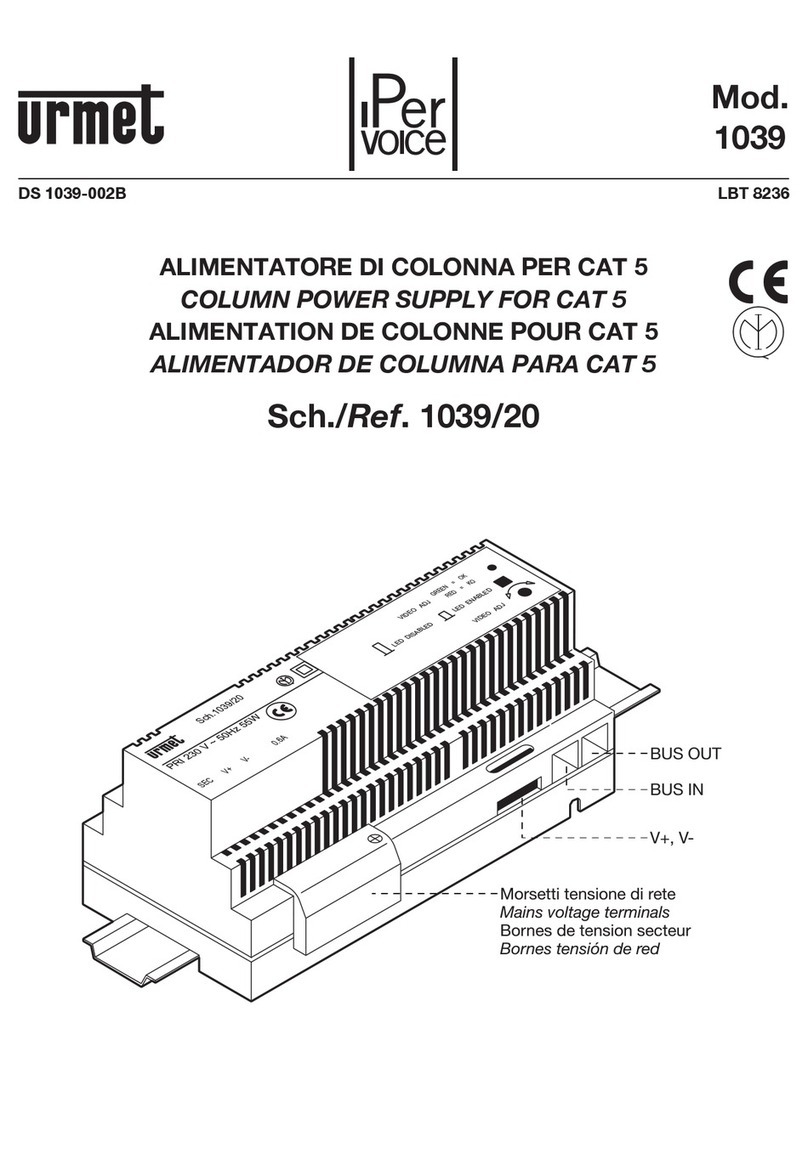
DESCRIZIONE
L’alimentatore videocitofonico Sch. 1039/20 è stato progettato tenendo conto delle norme di sicurezza EN
60065 e 64/8 vigenti, ed è provvisto del marchio IMQ.
L’alimentatore Sch. 1039/20 può essere impiegato esclusivamente negli impianti videocitofonici Ipervoice.
CARATTERISTICHE
Alimentazione: 230Vca +/- 10% 50Hz
Potenza: 55W
Uscita V+, V-: 54Vdc 0,6A
con protezione elettronica contro sovraccarichi di corrente
Temperatura: -5°C ÷ 45°C
Dimensioni: 180 x 80 x 90mm (10 moduli DIN)
Peso: circa 450g
INSTALLAZIONE
Per la realizzazione dei cablaggi, per le massime distanze e per le operazioni di configurazione si
raccomanda di seguire le regole prescritte nel manuale di sistema.
Il contenitore è adatto sia al montaggio su barra DIN che a parete a mezzo viti e tasselli e deve essere
installato in luoghi asciutti e riparati dalle intemperie.
La tensione di alimentazione è unica ed è di 230V in accordo alle nuove normative Europee.
Per i collegamenti usare i connettori RJ45 Urmet 1039/101 come prescritto sull’etichetta.
Inserire i conduttori nella guida rispettando le colorazioni indicate (Standard T568B).
REGOLAZIONE SEGNALE VIDEO
Effettuare la regolazione del segnale video partendo dall’alimentatore più vicino al GATEWAY Sch.1039/50
e procedendo in ordine fino al piùdistante, secondo la seguente procedura:
1. Mettere il sistema in modalità“taratura video”premendo il pulsante posto sulla cappa del GATEWAY
Sch. 1039/50.
2. Premere lo switch accessibile dalla cappa dell’alimentatore: si accende il led a due colori (rosso-verde).
3. Ruotare il trimmer di regolazione in modo che il led diventi di colore verde: in questo modo il segnale
video in uscita dell’alimentatore ècorrettamente regolato.
4. Al termine della taratura premere lo switch dell’alimentatore e il pulsante del GATEWAY Sch.1039/50.
ATTENZIONE: se non si èin modalità“taratura video”il led acceso compariràcomunque di colore rosso
anche se il sistema ècorrettamente tarato.
In caso di sostituzione di un alimentatore occorre rieffettuare la taratura solo sul dispositivo interessato
ripetendo la procedura descritta.
DESCRIPTION
The video power supplyRef. 1039/20 has been projected in compliance with the existing securityrules and
it is provided with IMQ certificate.
The power supplyRef. 1039/20 can onlybe used in video systems Ipervoice.
FEATURES
Power supply: 230Vca +/- 10% 50Hz
Power: 55W
Output V+, V-: 54Vdc 0,6A
with electronic protection against current overload
Temperature: -5°C ÷45°C
Dimensions: 180 x 80 x 90mm (10 modules DIN)
Weight: approximately 450g
INSTALLATION
Refer to the instructions contained in the system manual for wiring, maximum distances and configuration
operations.
The housing maybe used both in DIN bar mounting and wall mounting bymeans of screws and spacers;
please take care of mounting it in dryand repaired environments.
The voltage is 230V in compliance with the new European rules.
Use Urmet 1039/101 RJ45 connectors as shown on the label.
Insert the wires in the guide respecting the colour coding shown (Standard T568B).
VIDEO SIGNAL ADJUSTMENT
Adjust the video signal from the power unit closest to the GATEWAY Ref.1039/50 and proceed in sequence
to the most distant power unit as shown below:
1. Set the system to “video calibration”mode bypressing the button on the hood of the GATEWAY Ref.
1039/50.
2. Press the switch accessible on the power unit hood: the two colour (red-green) LED will light up.
3. Turn the adjustment trimmer so that the LED turns green: the video signal output from the power unit will
be correctlyadjusted.
4. At the end of the calibration procedure, press the switch on the power unit and the button on the
GATEWAY Ref. 1039/50.
IMPORTANT: The LED will be red even if the system is correctlycalibrated if “video calibration”mode is not
selected.
Recalibrate the system by repeating the procedure described above if a power unit is replaced.


