Ursalink UG65 User manual

1
UG65 LoRaWAN Gateway
Quick Start Guide
Ursalink Technology Co., Ltd.

www.ursalink.com
2
Welcome
Thank you for choosing Ursalink UG65 LoRaWAN Gateway.
This guide teaches you how to install the UG65 and how to log in the web GUI to configure the device. Once
you complete the installation, refer to the Ursalink UG65 User Guide for instructions on how to perform
configurations on the device.
Related Documents
This Quick Start Guide only explains the installation of Ursalink UG65 LoRaWAN Gateway. For more
functionality and advanced settings, please refer to the relevant documents as below.
Document
Description
Ursalink UG65 Datasheet
Datasheet for the Ursalink UG65 LoRaWAN Gateway.
Ursalink UG65 User Guide
Users can refer to the guide for instruction on how to log in the
web GUI, and how to configure all the settings.
The related documents are available on Ursalink website: https://www.ursalink.com.
Declaration of Conformity
UG65 is in conformity with the essential requirements and other relevant provisions of the CE, FCC, and
RoHS.
For assistance, please contact
Ursalink technical support:
Email: support@ursalink.com
Tel: 86-592-5023060
Fax: 86-592-5023065
Revision History
Date
Doc Version
Description
August 31, 2020
V1.0
Initial version

Ursalink UG65 Quick Start Guide
www.ursalink.com
3
Contents
1. Packing List.......................................................................................................................................................4
2. Hardware Introduction.....................................................................................................................................5
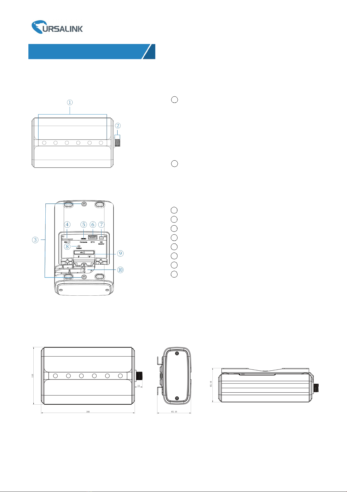
2.1 Overview................................................................................................................................................ 5
2.2 Dimensions.............................................................................................................................................5
2.3 LED Indicators.........................................................................................................................................6
2.4 Reset Button...........................................................................................................................................6
3. Hardware Installation.......................................................................................................................................7
3.1 SIM Card Installation.............................................................................................................................. 7
3.2 Ethernet Cable & Power Cable Installation............................................................................................7
3.3 Antenna Installation...............................................................................................................................7
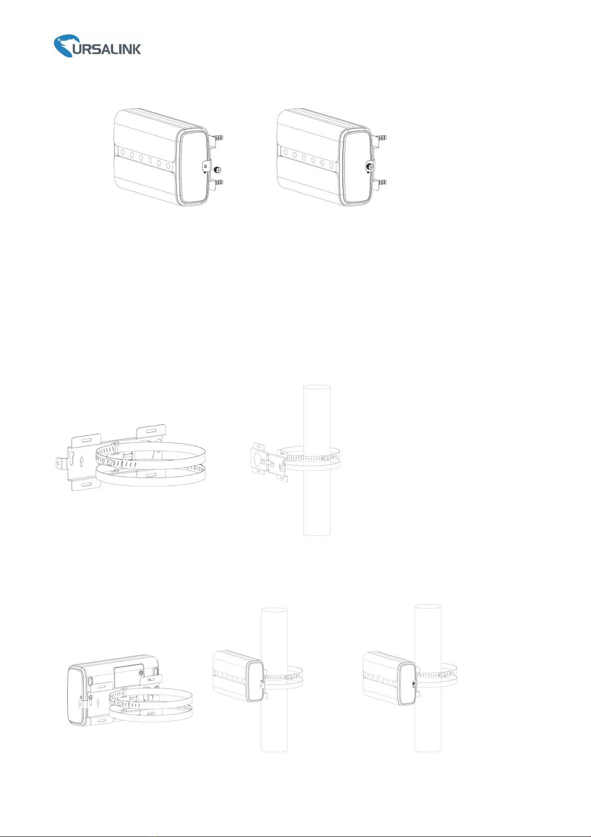
3.4 Gateway Mounting.................................................................................................................................8
3.4.1 Wall Mounting.............................................................................................................................8
3.4.2 Pole Mounting.............................................................................................................................9
4.Access the Web GUI of UG65..........................................................................................................................10
4.1 Web GUI Access via Wi-Fi.................................................................................................................... 10
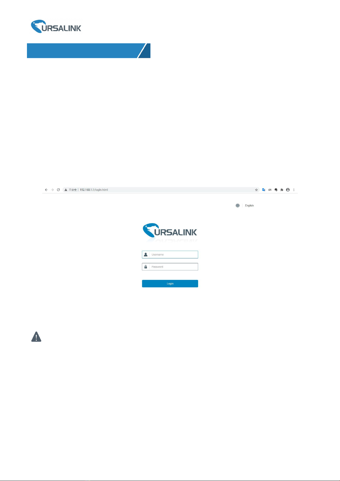
4.2 Web GUI Access via Ethernet Port....................................................................................................... 11
5.Connect UG65 to the Netowork..................................................................................................................... 13
5.1 Configure the WAN Connection...........................................................................................................13
5.2 Configure the Wi-Fi Connection...........................................................................................................14
5.3 Configure the Cellular Connection.......................................................................................................15
6.Packet Forwarder Configuration..................................................................................................................... 17
7. Network Server Configuration....................................................................................................................... 19
7.1 Connect UG65 to Ursalink Cloud......................................................................................................... 19
7.2 Connect UG65 to Other Platform........................................................................................................ 21

Ursalink UG65 Quick Start Guide
www.ursalink.com
4
1. Packing List
Before you begin to install the UG65 LoRaWAN Gateway, please check the package contents to verify that
you have received the items below.
Bracket Fixing Screws
& Grounding Screw
Wall Mounting Kits
1 × Warranty Card
1 × LoRa Antenna
(Optional)
If any of the above items is missing or damaged, please contact your Ursalink sales
representative.
1 × UG65
1 × Ethernet Cable
1 × DC Jack Power Adapter
1 × Mounting Bracket

Ursalink UG65 Quick Start Guide
www.ursalink.com
5
2. Hardware Introduction
2.1 Overview
A. Front Panel
B. Rear Panel
2.2 Dimensions (mm)
1LED Area
POWER: Power Indicator
STATUS: System Indicator
LoRa: LoRa Indicator
Wi-Fi: Wi-Fi Indicator
LTE: Cellular Indicator
ETH: Ethernet Port Indicator
2LoRa Antenna Connector
(only for external antenna version)
3Bracket Mounting Screws
4SIM Slot
5Type-C Port
6Ethernet Port (PoE)
7Power Connector
8Reset Button
9Waterproof Silicone
10 Cable Groove

Ursalink UG65 Quick Start Guide
www.ursalink.com
6
2.3 LED Indicators
LED
Indication
Status
Description
POWER
Power Status
Off
The power is switched off
On
The power is switched on
STATUS
System Status
Blue Light
Static: the system is running properly
Red Light
The system goes wrong
LoRa
LoRa Status
Off
Packet Forwarder mode is running off
Blue Light
Packet Forwarder mode is running well
Wi-Fi
Wi-Fi Status
Off
Wi-Fi is disabled
Blue Light
Wi-Fi is enabled
LTE
Cellular Status
Off
SIM card is registering or fails to register
(or there are no SIM cards inserted)
Blue Light
Blinking slowly: SIM card has been registered and is
ready for dial-up
Blinking rapidly: SIM card has been registered and
is dialing up now
Static: SIM card has been registered and dialed up
successfully
ETH
Ethernet
Port Status
Off
Disconnected
Blue Light
Static: Connected
2.4 Reset Button
Function
Description
STATUS LED
Action
Reset
Static Blue
Press and hold the reset button for more than 5 seconds.
Static Blue →
Rapidly Blinking
Release the button and wait.
Off → Static Blue
The gateway resets to factory default.

Ursalink UG65 Quick Start Guide
www.ursalink.com
7
3. Hardware Installation
3.1 SIM Card Installation
UG65 does not support hot plugging (also called hot swapping). please turn off the power before you
insert or take off cards.
A. Use screwdriver to open the protective cover on the back panel of UG65.
B. Insert the SIM card into the device according to the direction icon on the device.
Note: If you need to take out the SIM card, press into the SIM card and it will pop up automatically.
3.2 Ethernet Cable & Power Cable Installation
A. Connect the Ethernet cable and power cable to corresponding interfaces.
B. Pass two cables through the waterproof silicone and slid into the grooves.
C. Screw the protective cover back to the device.
UG65 also supports 802.3af standard PoE and can be powered by PoE switch or PoE adapter. When
connecting, Ethernet cable of UG65 device side should be installed first, otherwise, PoE devices or gateway
may be damaged.
3.3 Antenna Installation
For external antenna version, rotate the antenna into the antenna connector accordingly.
The external antenna should be installed vertically always on a site with a good signal.

Ursalink UG65 Quick Start Guide
www.ursalink.com
8
3.4 Gateway Mounting
The gateway can be mounted to a wall or a pole. Please complete all software configurations before
installation.
3.4.1 Wall Mounting
Preparation: mounting bracket, bracket fixing screws, grounding screw, wall plugs, wall mounting screws and
other required tools.
1. Before you start, make sure that your SIM card has been inserted, your antennas have been attached and
all cables have been installed.
Note: Do not connect device to power supply or other devices.
2. Align the mounting bracket horizontally to the desired position on the wall, use a marker pen to mark
four mounting holes on the wall, and then remove the mounting bracket from the wall.
Note: The connecting lines of adjacent points are at right angles.
3. Drill four holes with a depth of 32 mm by using your drill with a 6 mm drill bit on the positions you
marked previously on the wall.
4. Insert four wall plugs into the holes respectively.
5. Mount the mounting bracket horizontally to the wall by fixing the wall mounting screws into the wall
plugs.
6. Screw the bracket fixing screws to the back panel of device, then hang the device to the mounting
bracket on the wall.

Ursalink UG65 Quick Start Guide
www.ursalink.com
9
7. Screw the grounding screw to fix UG65 to the mounting bracket.
3.4.2 Pole Mounting
Preparation: mounting bracket, bracket fixing screws, hose clamp and other required tools.
1. Before you start, make sure that your SIM card has been inserted, your antennas have been attached and
that all cables have been installed.
Note: Do not connect device to power supply or other devices.
2.Loosen the hose clamp by turning the locking mechanism counter-clockwise.
3.Straighten out the hose clamp and slide it through the rectangular rings in the mounting bracket, wrap the
hose clamp around the pole.
4.Use a screwdriver to tighten the locking mechanism by turning it clockwise.
5. Screw the bracket fixing screws to the back panel of device, then hang the device to the mounting bracket
on the pole.
6. Screw the grounding screw to fix UG65 to the mounting bracket.

Ursalink UG65 Quick Start Guide
www.ursalink.com
10
4.Access the Web GUI of UG65
Ursalink UG65 provides web-based configuration interface for management. If this is the first time you
configure the gateway, please use the default settings below:
ETH IP Address: 192.168.23.150
Wi-Fi IP Address: 192.168.1.1
Wi-Fi AP: Ursalink_******
Username: admin
Password: password
4.1 Web GUI Access via Wi-Fi
A. Choose the wireless network Ursalink_****** from the list and click Connect.
B. Open a Web browser on your PC (Chrome is recommended) and type in the IP address 192.168.1.1 to
access the web GUI.
C. Enter the username and password, click “Login”.
If you enter the username or password incorrectly more than 5 times, the login page will be locked
for 10 minutes.
D. When you log in with the default username and password, you will be asked to change password. It’s
suggested that you change the password for the sake of security. Click “Cancel” button if you want to modify
it later.
E. After you log in the Web GUI, you can view system information and perform configuration of the gateway.

Ursalink UG65 Quick Start Guide
www.ursalink.com
11
4.2 Web Access via Ethernet Port
Connect PC to UG65 ETH port directly or through PoE adapter. The following steps are based on Windows 10
operating system for your reference.
A. Go to “Control Panel” → “Network and Internet” → “Network and Sharing Center”, then click “Ethernet”
(May have different names).
B. Go to “Properties” → “Internet Protocol Version 4(TCP/IPv4) ”and select “Use the following IP address”,
then assign a static IP manually within the same subnet of the gateway.

Ursalink UG65 Quick Start Guide
www.ursalink.com
12
C. Open a Web browser on your PC (Chrome is recommended) and type in the IP address 192.168.1.1 to
access the web GUI.
D. Enter the username and password, click “Login”.
If you enter the username or password incorrectly more than 5 times, the login page will be locked
for 10 minutes.
E. When you log in with the default username and password, you will be asked to change password. It’s
suggested that you change the password for the sake of security. Click “Cancel” button if you want to modify
it later.
F. After you log in the Web GUI, you can view system information and perform configuration of the gateway.

Ursalink UG65 Quick Start Guide
www.ursalink.com
13
5.Connect UG65 to the Netowork
This section explains how to connect the gateway to network via WAN connection, Wi-Fi or cellular.
5.1 Configure the WAN Connection
A. Go to “Network”→ “Interface” → “Port” page to select the connection type and configure Ethernet port
information.
B. Click “Save & Apply” for changes to take effect.
C. Connect Ethernet port of gateway to devices like router or modem.
D. Log in the web GUI via the newly assigned IP address and go to “Status”→ “Network” to check Ethernet
port status.

Ursalink UG65 Quick Start Guide
www.ursalink.com
14
5.2 Configure the Wi-Fi Connection
A. Go to “Network” → “Interface” → “WLAN” and select “Client” mode.
B. Click “Scan” to search for Wi-Fi access point. Select the available one and click “Join Network”.
C. Type the key of Wi-Fi.
D. Go to “Status”→”WLAN” to check Wi-Fi status. If it shows “Connected”, it means gateway connects to
Wi-Fi successfully.

Ursalink UG65 Quick Start Guide
www.ursalink.com
15
5.3 Configure the Cellular Connection
A. Go to “Network” → “Interface” → “Cellular” → “Cellular Setting” page to enable cellular settings.
B. Choose relevant network type and fill in SIM card information like APN or PIN code.
C. Click “Save” and “Apply” for changes to take effect.

Ursalink UG65 Quick Start Guide
www.ursalink.com
16
D. Go to “Status” → “Cellular” page to view the status of the cellular connection. If it shows “Connected”, it
means the SIM has dialed up successfully. On the other hand, you can check the status of LTE indicator. If it
keeps on green light statically, it means SIM has dialed up successfully.

Ursalink UG65 Quick Start Guide
www.ursalink.com
17
6.Packet Forwarder Configuration
UG65 has embedded multiple packet forwarders like TTN and Chirpstack. This section explains how to
connect the gateway to third-party network servers.
Make sure the gateway connects to the network as shown in Section 5.
A. Go to “Packet Forwarder” → “General” page and click to add a network server.
B. Fill in the server information and enable this server.
Note:When you select any of TTN or Chirpstack, other servers are not allow to enable.
C. Go to “Packet Forwarder” → “Radio” page to configure antenna transmission type, center frequency and
channels. The channels of the gateway and network server need to be the same.
Note: for built-in antenna models, please select “2 ×Built-in ANT”; for external antenna models, please
select “Ext ANT(TX+RX)+ Built-in ANT(RX)”.

Ursalink UG65 Quick Start Guide
www.ursalink.com
18
D. Add the gateway on network server page. Take TTN for example, type and save the gateway EUI and
other information when you connect it via Semtech packet forwarder. After you add the gateway, TTN will
show connection status.
E. Go to “Traffic” page to view the data communication of UG65.

Ursalink UG65 Quick Start Guide
www.ursalink.com
19
7. Network Server Configuration
UG65 can work as network server and transmit data to Ursalink Cloud or other platform via
MQTT/HTTP/HTTPS.
Make sure the gateway connects to the network as shown in Section 5.
7.1 Connect UG65 to Ursalink Cloud
A. Go to “Packet Forwarder” → “General” page to enable the “Ursalink” type server.
B. Go to “Packet Forwarder” → “Radio” page to select the antenna transmission type, center frequency and
channels. The channels of the gateway and LoRaWAN nodes need to be the same.
Note: for built-in antenna models, please select “2 ×Built-in ANT”; for external antenna models, please
select “Ext ANT(TX+RX)+ Built-in ANT(RX)”.

Ursalink UG65 Quick Start Guide
www.ursalink.com
20
C. Go to “Network Server” → “General” page to enable the network server and Ursalink Cloud mode.
D. Register and log in the Ursalink Cloud (cloud.ursalink.com).
E. Go to “Gateway” page and click “Add” to add a gateway.
Table of contents
Other Ursalink Gateway manuals

Ursalink
Ursalink UG87 User manual

Ursalink
Ursalink UG85 User manual

Ursalink
Ursalink UG85 User manual

Ursalink
Ursalink UG87 User manual

Ursalink
Ursalink LoRa User manual

Ursalink
Ursalink urbana GI01 User manual

Ursalink
Ursalink UR75 Edge User manual

Ursalink
Ursalink UG87-In User manual

Ursalink
Ursalink UG87-LW User manual