manuals.online logo
Brands
  1. Home
  2. •
  3. Brands
  4. •
  5. US Robotics
  6. •
  7. Modem
  8. •
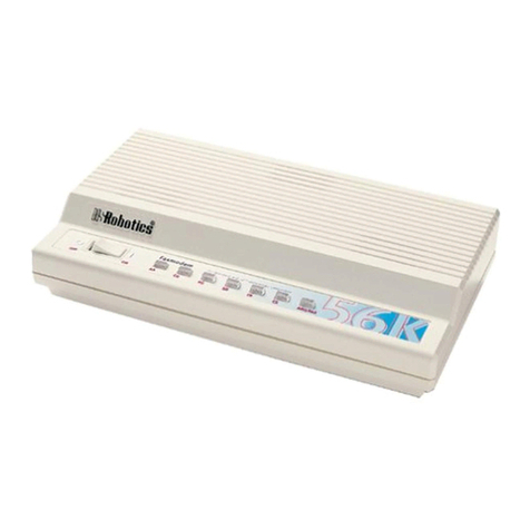
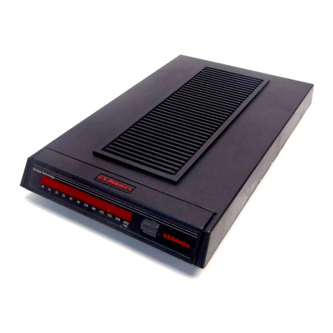
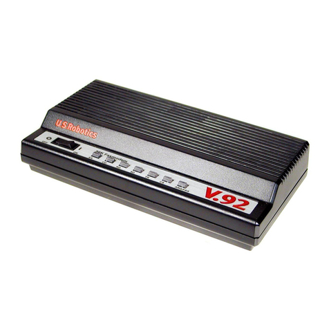
  9. US Robotics COURIER HST User manual

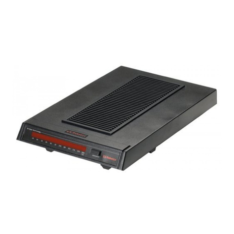
US Robotics COURIER HST User manual

--
[]11ilobotic:;
-------
-COURIER
HST™-
----
MODEM
-
9600
/
2400
/
1200
/
300
BPS, AUTO DIAL, AUTO ANSWER
MODEM
M610
-01
01
-00
WITH USR
HSr
MERROR CONTROL
USER'S
MANUAL
USRobotics, Inc.
8100 North McCormick Blvd.
Skokie.
IL
60076
c
1986.
All
Rights
Re
se
rved
Courier
HST
is
a trademark
of
USRobotics. Inc.
Touch-Tone
and
Di
gital Data Service
(DDS)
are trademarks
of
American Telephone and Telegraph. MCI Mail is a service
mark
of
MCI
Communications.
Incorporated. Microcom Networking Protocol
(MNP)
is
a trademark
of
-"'1icrocom. Inc. Sprint
is
a trademark
of
General Telephone and
Electric.
Limited
Warranty
FCC
Registration
Connecting
to the
Telephone
Company
Radio
and
Television
Interference
For
Canadian
Modem
Users
How
to Use this Manual
COURIER HST
TABLE
OF CONTENTS
Vil
Vlll
VIII
IX
X
XI
PART
I.
INSTALLATION
AND
OPERATION
CHAPTER
I-Introduction
USR-HST
Trellis
Coded
Modulation
Asymmetric
Modulation
Enhanced
Error Control
Shorter
Response
Time
The
Courier
Product
Family
Courier
HST
Compatibility
CHAPTER
2-Set-Up
and
Testing
Package
Components
Operational
Requirements
Assembling
the
Modem
Testing
Analog
Loopback Self-Test
Additional Test Procedures
CHAPTER
3-0perations
at a
Glance
Data
Format
Error
Control
Dialing
HST-Compatible,
9600
bps
MNP-Compatible,
2400
or
1200 bps
Non-MNP
Compatible,
2400,
1200,
300
bps
Flow Control
Maximum
Throughput
High-Speed
Channel
Turnaround
Link Negotiation
Data
Rate Defaults
Nonvolatile
Memory
(NRAM)
Phone
Number
Storage
Dialing Stored
Numbers
1-1
1-1
1-1
1-1
1-1
1-1
1-3
2-1
2-1
2-1
2-2
2-5
2-6
2-7
3-1
3-1
3-1
3-1
3-1
3-1
3-2
3-2
3-2
3-2
3-2
3-3
3-3
3-3
3-3
iii
COURIER HST
IV
Busy Answer
Inactivity
Timer
CHAPTER
4-Interface
Controls
Terminology
Error Control
ARQ
Retry
Timer
Error Control Modes (&Mn)
With Auto Answer
Flow Control
Commands
Transmit Data Flow Control (&Hn)
Received Data Flow Control
Software Control (&In)
Hardware Control (&Rn)
Data Rate
Commands
Optional Fixed Rates
Terminal Rate Select (&Bn)
Link Rate Select (&Nn)
Rate-Select Guidelines
DSR Override (&Sn)
CHAPTER
5-Internal
Controls
Setting/Using Defaults
Writing Defaults to
NRAM
(&W)
Loading the Factory Defaults (&F)
Resetting to
NRAM
Defaults (Z)
Storing Telephone Numbers
(&Zn=
s)
Result Codes
Response Modes (Vn)
Result Code Sets
(Xn)
Result Codes Options Table
Options
Summary
Quiet Mode (Qn)
/ARQ
Result Codes (&An)
Local Echo
Command
Mode Local Echo (En)
Online Local Echo (Fn)
The Audio Monitor
Speaker Control (Mn)
Modem
Clock Usage (Kn)
Transmitter Enable/Disable (Cn)
Break Handling (&Yn)
The S-Registers
3-4
3-4
4-1
4-1
4-1
4-1
4-2
4-2
4-2
4-3
4-4
4-4
4-5
4-5
4-5
4-6
4-6
4-6
4-7
5-1
5-1
5-1
5-2
5-2
5-2
5-3
5-3
5-3
5-4
5-4
5-5
5-5
5-5
5-5
5-6
5-6
5-6
5-7
5-7
5-8
5-8
CHAPTER
6---Dialing and Answering
Basic Requirements
Transmission Rate
Error Control
Automatic Retrain
Placing Calls
Dial (D)
Dialing Type (T.
P)
Adaptive Dialing
Pause (,)
Dial and Return to
Command
Mode (;)
Dialing Letters
(")
Transferring Calls (')
Wait for a Second Dial Tone (W)
Wait for an Answer
((
i
t)
Reversing Originate/Answer Frequencies
Canceling Dialing
Redialing
Reexecute the Last
Command
(A/)
Automated Redialing
Continuous Repeat (> )
Continuous Reexecute (A> )
Exiting Repeat Mode
Dialing a Stored Number (DSn)
Pulse Dial Make/Break Ratio (&Pn)
Escape Code Operations ( + + +)
ARQ
Mode Response
Normal Mode Responses
Returning Online
(0)
Hanging UP (Hn)
Automatic Answering
Suppressing Auto Answer
Points to Remember
U.S./CCITT
Answer Tone (Bn)
CHAPTER
7-Queries
and Help Screens
User
Inquiries (In)
S-Register Query (Sr?)
Sl7
S20
COURIER HST
6-1
6-1
6-1
6-1
6-2
6-2
6-2
6-2
6-3
6-3
6-4
6-5
6-5
6-5
6-6
6-6
6-6
6-7
6-7
6-7
6-7
6-7
6-7
6-8
6-8
6-8
6-9
6-9
6-9
6-10
6-10
6-10
6-10
6-11
7-1
7-1
7-3
7-3
7-3
V
COURIER HST
vi
Phone Number Query
(&Z11
'
1)
Help Screens
Basic Command Set
($)
Extended Command Set
(&$)
S-Rcgister Functions (
S$)
Dialing
(0$)
PART
II.
REFERENCE
APPENDIX
A-Error
/Flow Control Concepts
Overview
Throughput
MNP
Service Classes
Error Detection/Retransmission
Flow Control
Example
I-Transmit
Data
Example
2-Received
Data
APPENDIX
B-Summaries
and Tables
The RS-232C Interface, with Pin Definitions
Front End Indicators
DIP
Switch Summary
Default Settings
S-Register Summary
ASCII Chart
APPENDIX
C-Alphabetic
al Command Summary
APPENDIX
0-Problems
and Solutions
If
You Still Have Problems
APPENDIX
E-Additional
Operational Information
Using Both Voice and Data Communications
High Speed/Low Speed Protocol
Retrain Sequence
PBX,
Dedicated Line, and Leased Line Operations
Hewlett Packard Installations
APPENDIX
F-Technical
Specifications
GLOSSARY
INDEX
7-4
7-4
7-4
7-5
7-5
7-6
A-1
A-1
A-1
A-1
A-2
A-3
A-4
A-4
B-1
B-1
.I
B-2. I
B-3. I
8-4.
I
B-5. I
B-6. I
C-1
D-1
0-3
E-1
E-1
.I
E-2. I
E-3. l
E-4. 1
E-5. I
F-1
G-1
LIMITED
WARRANTY
COURIER HST
U.S. Robotics. Inc.. warrants to the original
consumer
or
other
end user purchaser that this product
is
free from
defects
in
materials
or
workmanship
for a period
of
two
years from the date
of
purchase. During the warranty period.
and upon
proof
of
purchase, the product will be repaired
or
replaced (with the same
or
similar model) at
our
option.
without charge for either parts
or
labor. This warranty shall
not apply
if
the product
is
modified, tampered with. mis-
used.
or
subjected to abnormal working conditions.
REPAIR
OR
REPLACEMENT
AS
PROVIDED UNDER
THIS
WARRANTY
IS
THE
EXCLUSIVE REMEDY
OF
THE
PURCHASER.
THIS
WARRANTY
IS
IN
LIEU
OF
ALL
OTHER
WARRANTIES. EXPRESS
OR
IM-
PLIED,
INCLUDING ANY
IMPLIED
WARRANTY
OF MERCHANTABILITY
OR
FITNESS
FOR
A
PAR-
TICULAR
USE
OR
PURPOSE.
AND
U.S.
ROBOTICS
SHALL
IN
NO
EVENT
BE
LIABLE
TO
PURCHASER
FOR
INDIRECT
OR
CONSEQUENTIAL DAMAGES
OF
ANY
KIND
OR
CHARACTER.
Some states do not allow the exclusion
or
limitation
of
inci-
dental
or
consequential
damages
or
allow limitations on how
long an implied warranty lasts, so the above limitations
or
exclusion may not apply to you. This warranty gives you
specific legal rights, and you may also have
other
rights
which vary from state to state.
To
obtain service under this warranty. contact the U.S.
Robotics Technical Support Department at
800
/982-5151
(in Illinois, 312/
982-5151),
or
by mail at 8100 North
McCormick
Blvd.,
Skokie, Illinois. 60076. You will be
given a Return Materials Authorization
(RMA)
number
to
help us keep track
of
your warranty request.
Once
you have
received your
RMA
number,
take
or
mail the product, post-
age prepaid, to U.S. Robotics at the above address. Include
proof
of
the date
of
purchase. IMPORTANT: If you ship
your unit, pack it securely, be sure your
RMA
number
is
visible on the outside
of
the
package,
and ship it charges
prepaid and insured.
>-
Should you
encounter
problems in operating this device.
follow the instructions in Appendix D in Part lI
of
this man-
ual.
The
Appendix contains solutions to operating problems
as well as procedures to follow
if
there
is
an apparent
modem
malfunction.
vii
COURIER HST
FCC
REGISTRATION
viii
CONNECTING
TO THE
TELEPHONE
COMPANY
FCC68: CJE794-l l
323-DM
-E
RINGER
EQUIVALENCE:
048
FCCl5:
CJE
794FAST
It
is
not necessary to notify the telephone
comp
any before
in
stalling the
modem
.
Howev
er. the telephone
co
mpany may
request the telephone number(s) to which the Courier
is
con-
nected and the FCC information printed above.
If the telephone co
mp
any has any ques
ti
ons
or
raises prob-
lems, ask them to
ca
ll
the T
ec
hnical
Supp
o
rt
Department.
USRobotics. Inc.. 800/982-5151 (in Illinois. 312/982-5151).
If the modem
is
malfunctioning.
it
may affect the telephone
lines. In this
case.
dis
connect
the modem until the source
of
the difficulty
is
traced. Do not use the mo
dem
on party
or
co
in
telephone lines.
RADIO
AND
TELEVISION
INTERFERENCE
COURIER HST
This equipment generates and uses radio frequency energy
and if not installed and used properly.
in
strict accordance
with the
manufacturer's
instructions, may cause interference
to radio and television reception. The Courier
HST
has been
tested and found to comply with the limits for a Class B
computing device
in
accordance with the specifications
in
Subpart J
of
Part
15
of
FCC
rules. which are designed to
provide reasonable protection against such interference in
a residential installation.
However, there
is
no guarantee that interference will not
occur
in
a particular installation.
If
this device does cause
interference to radio
or
television reception, which you can
determine by monitoring reception when the modem
is
on
and off, try to correct the problem with one
or
more
of
the
following measures.
Reorient the receiving antenna.
Relocate the
computer
with respect to the receiver.
Relocate the
computer
and/or the receiver so that they are
on separate branch circuits.
If necessary, consult your dealer
or
an experienced radio/
television technician for additional suggestions. You may
find the following booklet, prepared by the Federal
Commu-
nications
Commission,
helpful:
How to Identify and Resolve Radio-TV Interference
Problems
Stock No.
004-000-0345-4
U.S.
Government
Printing Office
Washington,
DC
20402
ix
COURIER HST
X
FOR
CANADIAN
MODEM
USERS
Th
e
Canadian
Department
of
Communication
s (DOC) label
identifies certified equipment. This certification m
ea
ns that
the e
quipment
m
ee
ts
ce
rtain tel
eco
mmunications network
protective,
op
erational, and
saf
ety requirements.
Th
e depart-
ment
does
not guarantee the
equipment
will
op
erate to a
user's satisfaction.
B
efo
re installing this e
quipm
ent, ma
ke
sure you are permit-
ted to
connect
it
to the facilities of the local tel
eco
mmuni-
ca
ti
ons
compan
y. You must also install the equipment using
an acceptable
method
of
connec
ti
on. In some cases, you
may also extend the c
ompan
y's
in
s
id
e wiring
fo
r s
in
g
le
line
individual serv
ic
e by means
of
a certified connector ass
em
-
bl
y (tele
phone
extension cord). You should be a
war
e, how-
ev
er
. that compliance with the above conditions may not
pr
event degradation
of
service
in
some
situations.
Repairs to certified e
quipment
should be made by an author-
ized
Ca
nadian maintenance facility designated by the sup-
plier. Any repairs
or
alterations made by a user to this
e
quipm
ent,
or
e
quipm
ent malfunc
ti
ons. may give the
tel
eco
mmunications co
mpany
ca
use to request the us
er
to disconnect the equipment.
Fo
r your own protec
ti
on, make sure that the electric
al
ground connec
ti
ons of the
pow
er utility. telephone lines,
and internal metallic water pipe system,
if
present, are con-
nected together. This precaution may be particularly
impor
-
tant
in
rural areas.
CAU
TION:
Do not attempt to make such
co
nn
ec
ti
ons
yourself;
conta
ct the appropriate electric inspec
ti
on authority
or electrician.
Courier
HST Modern L
oa
d Number: 388
Th
e Load
Numb
er (LN) assigned to each terminal device
denotes the perce
nt
age
of
the total load to be connected to
the telephone l
oo
p used by the de
vi
ce. without overloading.
The termination on a loop may
co
nsist
of
any combination
of devices. subject o
nl
y to the re
quir
ement that the total
of
the Load
Numb
ers
of
a
ll
the devices not exceed I00. An
alphabetic suffix is also specified
in
the Load N
umber
for
the appropriate ringing type (A
or
8).
if
applica
bl
e.
For
example. LN
=
388 designates a Load
Numb
er
of
38 and
a 8 -type rin
ge
r.
HOW
TO USE
THIS
MANUAL
COURIER HST
This manual
is
divided into two parts. The first part
is
designed to aid you
in
getting your modem connected and
operating as quickly as possible. Part I
al
so includes chap-
ters on
command
usage. Part
II
contains a number
of
informative appendixes that you may
or
may not need,
depending on your situation. plus a Glossary and Index.
Below
is
a brief description
of
the
manual's
contents. We
suggest you review at least Chapters
1-3
before operating
th
e modem.
• Chapter
I-Introduction
• Chapter
2-Assembling
and testing the modem
• Chapter
3-lmmediate
operations-essentials
• Chapter
4-Interface
controls
•
Chapter
5-Internal
controls
• Chapter
6-Calling,
answering and disconnecting
• Chapter
7-Inquiries
and Help screens
The appendixes in Pa
rt
II
cover
the following subjects:
• Background information on error and flow control
• Summaries and tables
• Problems, their causes, and solutions
• Additional operational information
• Technical specifications
Whenever a cross-reference
is
made to the same
or
a similar
subject,
you'
II
be directed to the appropriate section
of
the
manual with this arrowhead symbol,
~
xi
USR-HST
Trellis
Coded
Modulation
Asymmetric
Modulation
Enhanced
Error
Control
Shorter
Response
Time
THE COURIER
PRODUCT
FAMILY
MNP
Error
Control
at
2400/1200 BPS
COURIER HST
CHAPTER 1
INTRODUCTION
The USRobotics Courier HST modem represents powerful,
advanced electronic design that gives you optimal speed and
accuracy. USRobotics' High Speed Technology (USR-HST)
offers these advantages:
Trellis coded modulation
is
a convolutional coding technique
that makes data transmission less vulnerable to errors caused
by
phone network impairments.
It
can tolerate twice the tel-
ephone channel noise power as conventional modulation
(quadrature amplitude modulation,
or
QAM), so there are
fewer error-control retransmissions. Trellis coded modula-
tion
is
also less susceptible to impulse-type noise.
At top speed, data flows
in
one direction at 9600 bits per
second and
at
300 bits per second
in
the other. The modems
automatically switch the high-speed channel on demand,
i.e.,
depending on which transmitter has the most data to
transmit. In practice, the modems seldom need to reverse
channels, since the asymmetric design reflects typical com-
munications sessions-brief messages typed at one end
of
the link, files sent from the other. The asymmetric approach
provides the most efficient and economical strategy for using
ordinary phone channels
at
high speeds.
The
HST
error control protocol uses sophisticated error
detection methods to ensure data integrity. Design effi-
ciencies have reduced the overhead (extra control infor-
mation) experienced with error control protocols at lower
speeds. On local and long-distance connections the result
is
accuracy. greater speed and higher
throughput-
approximately 1100 characters per second.
9600-bps modems are generally most efficient for file trans-
fers. You'll find that the Courier HST also offers faster
response times during interactive sessions.
In addition to the Courier
HST's
new features, the modem
incorporates the same popular capabilities
of
other products
in
the Courier line:
The Courier HST implements the Microcom Networking
Protocol (MNP), Service Classes
l,
2, and 3, at 2400 and
l200 bits per second. This ensures compatibility with the
Courier 2400e and other MNP-compatible modems at
those speeds.
1-1
COURIER HST
Data Rate
Fallback
Inactivity
Timer
Call
Duration
Reporting
Ca
11
Progress
Detection
Modem
Settings
Display
HELP
Screens
Bottom
Panel
Reference
Repeat
Commands
Quote
Mode
Adaptive
Dialing
1-2
Automatic
Retraining
The
Courier
HST
automatically falls back to 2400. 1200.
and
300
bits
per
second. in both
Originate
and
Answer
Modes, to match a lower rate
of
a called
or
calling
modem.
You can optionally set local interface and link rates at
fixed speeds.
You
can
set the
modem
to automatically
hang
up after a
specified
number
of
minutes if there is no activity
on
the
phone
line.
The
modem
records the duration
of
your
calls in hours,
minutes,
and
seconds.
This
feature
enables
you to display
and print an audit
of
your
calling activities. You can option-
ally use the
modem
clock
as a real-time clock.
An optional set
of
result
codes
(screen messages) lets you
know
when
a line
is
busy, a person rather than a
modem
has
answered
the
phone,
there
is
no dial tone,
or
the distant
phone
is ringing.
On
command,
the
modem
displays its current settings, a
handy way to
check
your
transmission rate, S-registers and
other
operational controls.
You
can
also
displa
y screens that
summarize
the
command
sets. Dial
command
options,
and S-register functions.
Operational
summaries
and
other
information are printed
on
the
bottom
of
the
modem
case. A Dual In-Linc
Package
(DIP) switch guide
makes
it
easy to tailor the switch set-
tings to
your
requirements.
You can have the
modem
continuously repeat a
command
until you instruct
it
otherwise.
This
is
especially useful in
dialing services
whose
lines are often busy.
Set the
modem
to
Quote
Mode
if
you want
it
to dial
an alphabetic
"number,"
such as
800-"DIAL
USR"
(USRobotics'
Sales
Department).
You
can
set the
modem
to first try
Touch-Tone
dialing.
If
tone dialing
doesn
't work
on
the line. the
modem
automatic-
ally
switches
to the
slower
type,
pulse (rotary).
Retraining
(a
resynchronization with the remote
modem)
occurs
if
the
modem
detects line disturbances that might
affect
data
reliability. At
9600
bps the
connection
must be
with an
HST-compatible
modem.
Retraining also
occurs
at
COURIER
HST
COMPATIBILITY
COURIER HST
2400 bps if the
other
modem
is
Y.22bis-compatible.
(>
Ap-
pendix E-3 contains more information.)
The
Courier
HST
offers upgrading to
9600
bps while main-
taining compatibility with most installed 2400/I200/300 bps.
dial-up modems and existing software. Its compatibility
features include the following:
• Can be used with any
computer
or
terminal that
is
compatible with the RS-232C standard interface.
(>
For more information on the
RS-232C
interface.
see Appendix
8-
I .)
• Can be used with
any
computer
or
terminal that uses
ASCII,
the standard character code supported by most
equipment
manufacturers.
•
Connects
with any
modem
whose signal
scheme
is
compatible
with the following standards at the given
data
rate:
300
bps
1200 bps
2400
bps
9600
bps
Bell
!03
Bell 212A
V.22bis
USR-HST
• Uses the
HST
error
control protocol at
9600
bps
and.
optionally. the
MNP
error
control protocol, Service
Classes
I.
2
and 3 at
2400/1200
bps.
•
Is
fully FCC-certified for the uses described in this
manual.
1-3
PACKAGE
COMPONENTS
OPERATIONAL
REQUIREMENTS
COURIER HST
CHAPTER 2
SET-UP AND TESTING
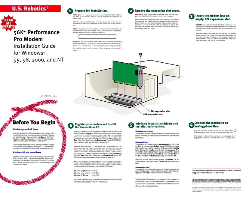
Figure 2.
]-Courier
HST
The
box
containin
g
yo
ur
Courier
HST
contains
the following
it
ems in additi
on
to this
manu
al:
•
The
Courier
HST
mod
em
• An
RJ
I IC
phone
cord
• A
power
adapter
• A
Quick-R
efe
rence
card
,
in
the
manu
al
•
Your
warranty
card,
to be filled
out
and returned to
U
SRoboti
cs.
Inc.
The
Courier
HST
has
minimal
operational
requirements.
Be
sure to read the
information
in the front
of
this
manual
about
radio
and
television interference
and
connecting
to the
phon
e
co
mpany.
In
addition.
you
should be
aware
of
the following:
•
Follow
the
operating
instructions in
Appendix
E-4
if
the
mod
em is to be used in
either
of
the following
types
of
in
stallation.
IJ
The
modem
will be installed in a k
ey
system
PBX
in
which
RJ
12
or
RJ
13
telephone
ja
cks
are used
rather than the
RJ
I I jack.
2)
The
modem
will be attached to a user-installed
phone line
or
a line l
ease
d from the
telephone
company.
Often
r
efe
rred to as
"dedi
ca
ted"
or
"private
...
this type of line is used for a
dir
ec
t.
2-1
COURIER HST
2-2
ASSEMBLING
THE
MODEM
continuous connection between two modems.
The connection
is
made without dialing.
•
If
the modem
is
installed in a Hewlett Packard system,
be sure to follow the instructions
in
Appendix E-5.
•
If
you're working with a computer rather than a ter-
minal, the computer must be in Terminal Mode.
If
you're not familiar with this requirement, check the
Glossary and refer to your communications software
documentation for instructions.
• You'll need an RS-232C cable to connect the modem
to your computer or terminal. It should be a shielded
cable to ensure minimal interference with radio and
television reception. (~ For information on the RS-
232C interface, see Appendix B-1.)
The modem takes a DB-25P (25-pin plug) connector,
but computer equipment varies: check the serial port
at the rear
of
your machine. The port will be labeled
"Modem,"
"Communications,"
or
"EIA,"
or
with a
phone symbol. (Don't use the port marked
"Printer"
or
"Aux.")
If
the port
is
a plug, specify a DB-25S
(socket) connector to your dealer. If the port
is
a
socket, specify a DB-25P (plug) connector. If your
machine has other than a 25-pin port, check your
documentation to see what type
of
RS-232C con-
nector
is
required.
I. Turn
off
the computer
or
terminal and its peripheral
devices.
2.
Examine the label on the bottom
of
the modem.
In
addi-
tion to the summaries and other information, the label
contains icons to aid
in
modem assembly. Then check
the interfaces at the back
of
the modem, shown in the
following photograph.
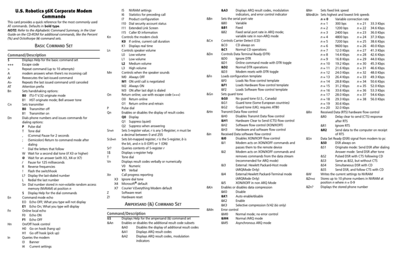
COURIER HST
Figure
2.2-lnterface
End, Courier HST
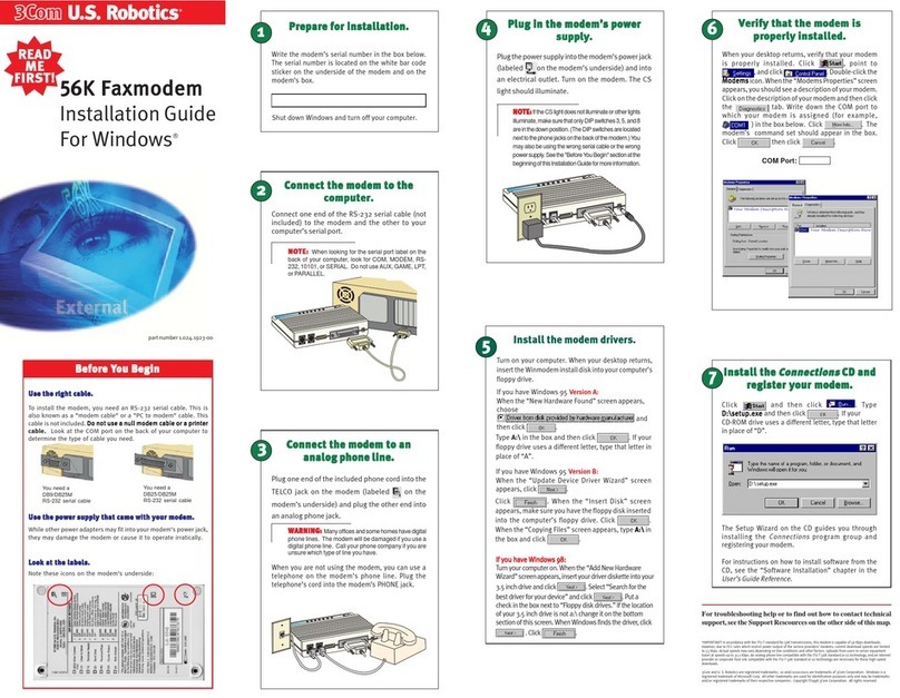
3.
Now
review the attached interfaces
in
Figure
2.3.
Figure
2.3-Connected
Courier HST
4. Check to make sure that the
power
switch
is
OFF; press
it
towards the zero in the
l/0
icon on the bottom label.
Then
plug the small end
of
the
power
supply cord into
the power jack at the back
of
the modem, and plug the
power
adapter into a standard 115-volts AC wall socket.
2-3

Other US Robotics Modem manuals

US Robotics SureConnect 9000 User manual

US Robotics

US Robotics SureConnect 9000 User manual

US Robotics Courier V.Everything x2 Addendum User manual

US Robotics

US Robotics Courier V.Everything x2 Addendum User manual

US Robotics USR5670 User manual

US Robotics

US Robotics USR5670 User manual

US Robotics 56K SERIAL CONTROLLER FAXMODEM User manual

US Robotics

US Robotics 56K SERIAL CONTROLLER FAXMODEM User manual

US Robotics Courier V.Everything User manual

US Robotics

US Robotics Courier V.Everything User manual

US Robotics 3CP5610A User manual

US Robotics

US Robotics 3CP5610A User manual

US Robotics 56K Series User manual

US Robotics

US Robotics 56K Series User manual

US Robotics 5630G - User manual

US Robotics

US Robotics 5630G - User manual

US Robotics USR5699C User manual

US Robotics

US Robotics USR5699C User manual

US Robotics USR5637 User manual

US Robotics

US Robotics USR5637 User manual

US Robotics SureConnect 9001 User manual

US Robotics

US Robotics SureConnect 9001 User manual

US Robotics USR5660A User manual

US Robotics

US Robotics USR5660A User manual

US Robotics Courier USR3453B User manual

US Robotics

US Robotics Courier USR3453B User manual

US Robotics 56K SERIAL CONTROLLER FAXMODEM User manual

US Robotics

US Robotics 56K SERIAL CONTROLLER FAXMODEM User manual

US Robotics 5633 Reference guide

US Robotics

US Robotics 5633 Reference guide

US Robotics 005689-03 User manual

US Robotics

US Robotics 005689-03 User manual

US Robotics 5686G User manual

US Robotics

US Robotics 5686G User manual

US Robotics 56K SERIAL CONTROLLER FAXMODEM User manual

US Robotics

US Robotics 56K SERIAL CONTROLLER FAXMODEM User manual

US Robotics 002605-00 - User manual

US Robotics

US Robotics 002605-00 - User manual

US Robotics 56K SERIAL CONTROLLER FAXMODEM User manual

US Robotics

US Robotics 56K SERIAL CONTROLLER FAXMODEM User manual

US Robotics 56K SERIAL CONTROLLER FAXMODEM User manual

US Robotics

US Robotics 56K SERIAL CONTROLLER FAXMODEM User manual

US Robotics 5686E User manual

US Robotics

US Robotics 5686E User manual

US Robotics USR5638 User manual

US Robotics

US Robotics USR5638 User manual

US Robotics 005690-00 User manual

US Robotics

US Robotics 005690-00 User manual

Popular Modem manuals by other brands

Multitech MultiModemDSVD user guide

Multitech

Multitech MultiModemDSVD user guide

H3 System H3G-900 Instruction

H3 System

H3 System H3G-900 Instruction

Motorola SURFboard SBV6120 Installation sheet

Motorola

Motorola SURFboard SBV6120 Installation sheet

Comtech EF Data DMD50 Installation and operation manual

Comtech EF Data

Comtech EF Data DMD50 Installation and operation manual

Paradyne COMSPHERE 3800 Series user guide

Paradyne

Paradyne COMSPHERE 3800 Series user guide

NETGEAR orbi CBR750 quick start guide

NETGEAR

NETGEAR orbi CBR750 quick start guide

Rae RAELink3 user guide

Rae

Rae RAELink3 user guide

Fibocom H330 Hardware user manual

Fibocom

Fibocom H330 Hardware user manual

Comtech EF Data CDM-750 Installation and operation manual

Comtech EF Data

Comtech EF Data CDM-750 Installation and operation manual

StarHub MF626 Quick user guide

StarHub

StarHub MF626 Quick user guide

Kantronics KAM Plus Getting started

Kantronics

Kantronics KAM Plus Getting started

Nokia RD-15 manual

Nokia

Nokia RD-15 manual

Dynamix UM-S Series quick start guide

Dynamix

Dynamix UM-S Series quick start guide

Devolo dLAN 200 DSpro manual

Devolo

Devolo dLAN 200 DSpro manual

Televes CoaxManager user guide

Televes

Televes CoaxManager user guide

Navini Networks Ripwave MX user guide

Navini Networks

Navini Networks Ripwave MX user guide

Cypress Chameleon CTM-15X Complete manual

Cypress

Cypress Chameleon CTM-15X Complete manual

O2 E173 user guide

O2

O2 E173 user guide

manuals.online logo
manuals.online logoBrands
  • About & Mission
  • Contact us
  • Privacy Policy
  • Terms and Conditions

Copyright 2025 Manuals.Online. All Rights Reserved.