manuals.online logo
Brands
  1. Home
  2. •
  3. Brands
  4. •
  5. UTEPO
  6. •
  7. Switch
  8. •
  9. UTEPO SF18P-LM User manual

UTEPO SF18P-LM User manual

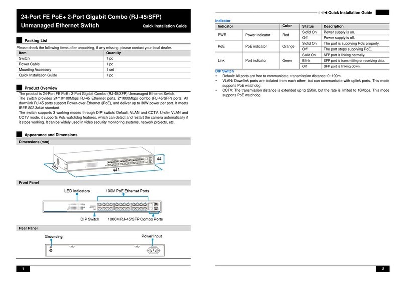
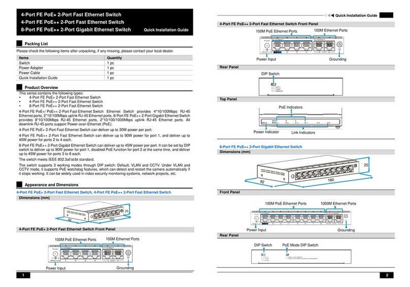
Feature
● Providing 16/24*10/100Mbps downlink Ethernet ports and 2*10/100/1000Mbps uplink
Ethernet ports.
● Support IEEE802.3, IEEE802.3u, IEEE802.3ab, IEEE802.3x, IEEE802.3af/at.
● Support 16/24* PoE ports, max PoE power output is 30W.
● One-key smart: Default, CCTV, VLAN.
● 6KV surge immunity, ESD protection.
● Operating temperature: -10℃~50℃.
● Plug and play, user-friendly operation. Support installation of desktop, wall mounted, and
rack mounted.
It is recommended to use the standard Cat5e/6 network cable to reach the optimal
transmission distance.
Cat5e/6
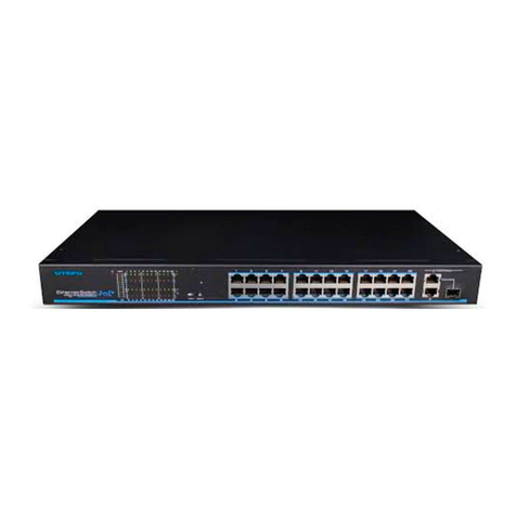
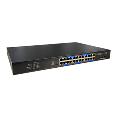
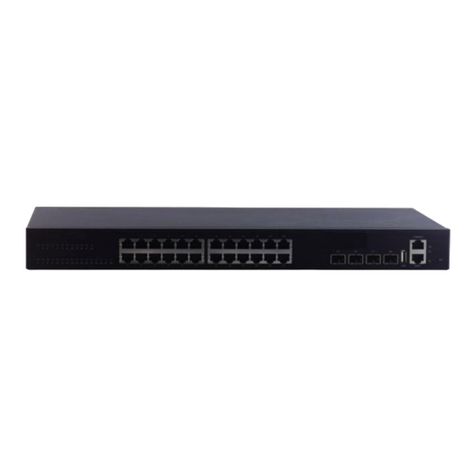
The series switches provide 16/24* (PoE) and 10/100Mbps downlink Ethernet ports
2*10/100/1000Mbps uplink Ethernet ports, which are widely used in HD video monitoring
system and network project etc. PoE ports 1~16/24 complies IEEE802.3af/at standard, and
PoE output power of each port can be up to 30W. The surge immunity level reaches 6kV and
ESD protection is up to 6kV contact discharge, 8kV air discharge. The switches support 3
operating modes (Default, VLAN, CCTV) and fully meet the application requirement of
security network video monitoring & networking project in hotel, campus, and small &
medium-sized enterprise.
13.238.101.1719
V2.0
LCD
NVR
PoE Camera
AP
PoE AP
PoE Camera
Application
PoE AP
Please follow installation steps as below:
1) Please turn off the signal source and the device's power, installation with power on
may damage the device.
2) Use network cables to connect IP cameras with the product's downlink Ethernet ports .
3) Use another network cable or (optical fiber) to connect switch’s uplink port with NVR
or computer.
4) Connect switch with power adapter.
5) Check if the installation is correct and device is good, make sure all the connection is
reliable and power up the system.
6) Make sure every network device power supply works normally.
Notice
Installation Steps
Board Diagram
Back
Front
LEDIndicator
DIP Switch
10/100Mbps PoE downlink Port
10/100/1000Mbps
uplink Port
LEDIndicator
DIP Switch
10/100Mbps PoE downlink Port
10/100/1000Mbps
uplink Port
12
Please check the following items before installation, if it is missing,
please contact the dealer.
● PoE Switch 1pc
● PowerCable1pc
● Mounting Kits 2pcs
● User Manual 1pc
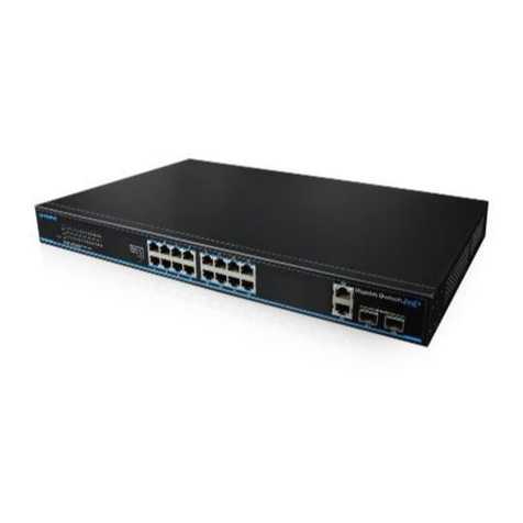
16/24-Port10/100MbpsPoESwitchwith2Gigabit UplinkPorts
UserManual
10/100Mbps PoE with
2-Port Gigabit Uplink Switch
16-Port10/100MbpsPoESwitchwith2Gigabit UplinkPorts
It is recommended that the equipment should be connected to the protection ground for
better protection performance, otherwise equipment protection will greatly reduced;
Please use 20AWG or thicker wire to connect grounding terminal to the ground.
Notice
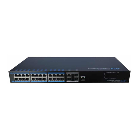
24-Port10/100MbpsPoESwitchwith2Gigabit UplinkPorts
16/24-Port10/100MbpsPoESwitchwith2Gigabit UplinkPorts
Notice
连接接口
连接接口
Trouble Shooting
Please find the following solution when the device doesn't work
连接接口
RJ 45 Making Method
pin color
white/green
green
blue
white/orange
white/blue
white/brown
orange
brown
1
2
3
4
5
6
7
8
pin color
1
2
3
4
5
6
7
8
white/green
green
blue
white/orange
white/blue
white/brown
orange
brown
EIA/TIA 568A EIA/TIA 568B
● When choose RJ-45 make sure if one end is EIA/TIA568A,the other end should also be EIA/TIA568A.
● When choose RJ-45 make sure if one end is EIA/TIA568B,the other end should also be EIA/TIA568B.
Instruments to be used: wire crimper, network tester. Wire sequence of RJ45 plug
should conform with EIA/TIA568A or 568B.
1) Shuck off about 2cm long the insulating layer, and bar the 4 pairs UTP cable;
2) Depart the 4 pairs UTP cable and straighten them;
3) Line up the 8 pieces of cables per EIA/TIA 568A or 568B;
4) Cut out 1.5 cm cable wrap and leave the bare wire;
) Plug 8 cables into RJ45 plug, make sure each cable is in each pin;
5
6) Then use wire crimper to crimp it;
7) Follow the 5 steps above to make the another end, following the same sequence of
the first plug;
8) Using network tester to test the cable whether is working.
34
连接接口
Specification
Products are subject to change without prior notice.
Item
Description
Model
16-Port 10/100M PoE Switch
24-Port 10/100M PoE Switch
Downlink Ports
16*10/100Base-T(PoE)
24*10/100Base-T(PoE)
Uplink Ports
2*10/100/1000Base-T RJ45
Standards
IEEE 802.3,802.3u,IEEE802.3ab,IEEE802.3z,IEEE802.3x
Switching Capacity
7.2Gbps
8.8Gbps
Packet Forwarding Rate
5.2Mpps
6.4Mpps
Forwarding Modes
store and forward
Packet Buffer
2.75Mbits
MACTable
8k
PoEStandard
802.3af/at(PSE)
PoEPin Assignment
1/2(+),3/6(-)
PoE Power Output
PoE(Single port)≤30W(54V DC)
Total PoE Budget≤135W
PoE(Single port)≤30W(54V DC)
Total PoE Budget≤225W
Three Working Modes
Default:All of the portscouldcommunicatefreely.
VLAN: Port 1-16/24 are isolated respectively, but can communicate with
uplink ports, support PoE watchdog.
CCTV: The transmission distance can be extended to 250 meter, while link
speed of downlink ports 1~16/24 will be limited to 10Mbps(Uplink ports
keep 100Mbps). Support PoE watchdog.
Surge Immunity
Common mode 6KV, Execute standard: IEC61000-4-5
ESD Protection
Contact discharge 6K, Air discharge 8KV,
Execute standard: IEC61000-4-2
Input Voltage
AC100~240; 50/60 Hz
Power Consumption
<10W
Operating Temperature
-10℃~50℃
Storage Temperature
-40℃~85℃
Operating Humidity
5%~95% (Non-condensing)
Dimension (W*D*H)
294mm*180mm*44mm
440mm*180mm*44mm
Weight
2kg
2.32kg
16/24-Port10/100MbpsPoESwitchwith2Gigabit UplinkPorts
Please confirm if the installation is correct.
Please confirm if the RJ-45 cable order is following the EI A/TIA568A or 568B
industry standards.
It can not exceed maximum 30 watts of each port.
Please replace the failed device with a normal one to check if the device is broken,
if the problem still exists, please contact the factory.
16/24-Port10/100MbpsPoESwitchwith2Gigabit UplinkPorts

This manual suits for next models

1

Other UTEPO Switch manuals

UTEPO UTP1-SW2402TS-POE User manual

UTEPO

UTEPO UTP1-SW2402TS-POE User manual

UTEPO UTP1-SW0401-TP60 User manual

UTEPO

UTEPO UTP1-SW0401-TP60 User manual

UTEPO UTP7204GE User manual

UTEPO

UTEPO UTP7204GE User manual

UTEPO UTP3-SW08-FP120 User manual

UTEPO

UTEPO UTP3-SW08-FP120 User manual

UTEPO UTP3306TS-PSB User manual

UTEPO

UTEPO UTP3306TS-PSB User manual

UTEPO UTP6306TS-PSD User manual

UTEPO

UTEPO UTP6306TS-PSD User manual
UTEPO UTP3306S-PSB User manual

UTEPO

UTEPO UTP3306S-PSB User manual

UTEPO UTP3318S-PSB250-M0 User manual

UTEPO

UTEPO UTP3318S-PSB250-M0 User manual

UTEPO SF6P-FHM User manual

UTEPO

UTEPO SF6P-FHM User manual

UTEPO utp3106-psb User manual

UTEPO

UTEPO utp3106-psb User manual

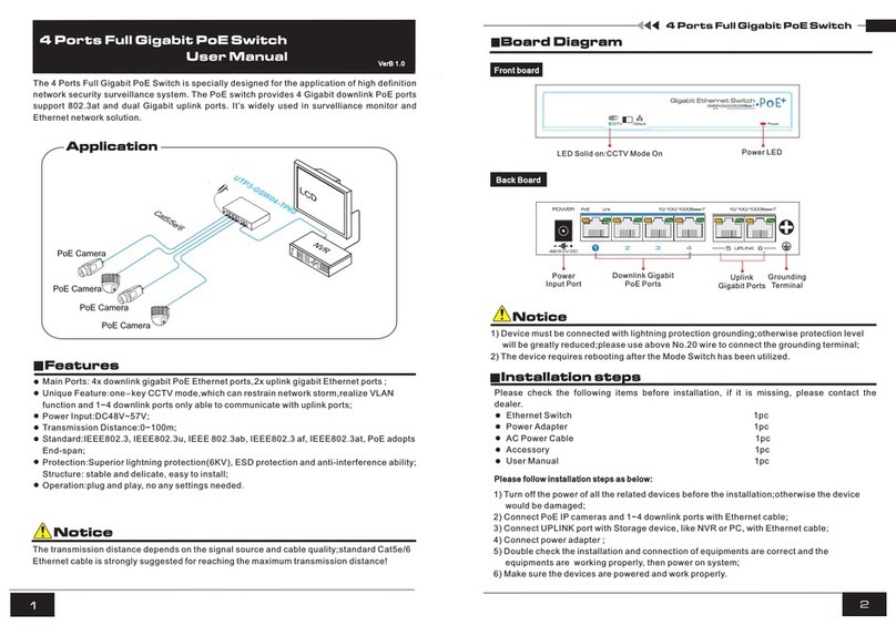
UTEPO UTP7624GS-L3 Specification sheet

UTEPO

UTEPO UTP7624GS-L3 Specification sheet

UTEPO MS60 User manual

UTEPO

UTEPO MS60 User manual

UTEPO UTP7304GE User manual

UTEPO

UTEPO UTP7304GE User manual

UTEPO SG16-M User manual

UTEPO

UTEPO SG16-M User manual

UTEPO UTP3310TS-PSB-L2 User manual

UTEPO

UTEPO UTP3310TS-PSB-L2 User manual

UTEPO UTP3-SW08-TP120 User manual

UTEPO

UTEPO UTP3-SW08-TP120 User manual

UTEPO UTP5628S-L3 User manual

UTEPO

UTEPO UTP5628S-L3 User manual

UTEPO N1-SW0801-TP120 User manual

UTEPO

UTEPO N1-SW0801-TP120 User manual

UTEPO UTP7624GE-PoE-P Specification sheet

UTEPO

UTEPO UTP7624GE-PoE-P Specification sheet

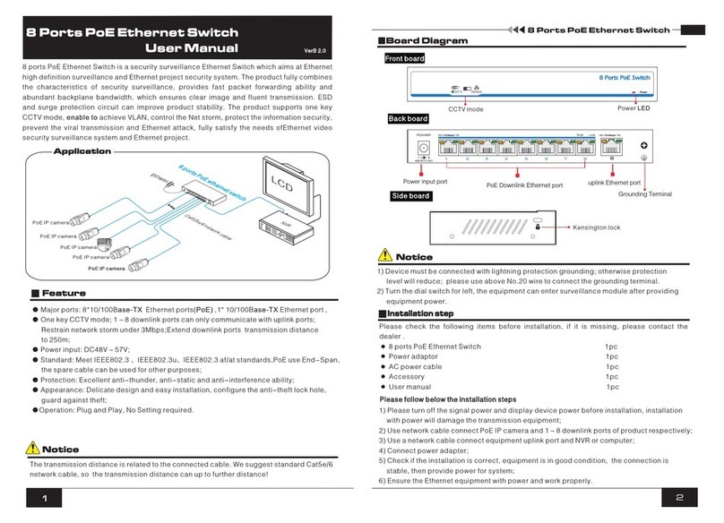
UTEPO 8 Ports PoE Ethernet Switch User manual

UTEPO

UTEPO 8 Ports PoE Ethernet Switch User manual

UTEPO UTP7310S-PSD240-W User manual

UTEPO

UTEPO UTP7310S-PSD240-W User manual

UTEPO UTP3-GSW04-TP60 User manual

UTEPO

UTEPO UTP3-GSW04-TP60 User manual

UTEPO UTP3226TS-PSB225 User manual

UTEPO

UTEPO UTP3226TS-PSB225 User manual
UTEPO UTP6306TS-PSD User manual

UTEPO

UTEPO UTP6306TS-PSD User manual
Popular Switch manuals by other brands

Avaya 8800 Series installation guide

Avaya

Avaya 8800 Series installation guide

Ruijie RG-S6510-48VS8CQ Hardware  installation and reference guide

Ruijie

Ruijie RG-S6510-48VS8CQ Hardware installation and reference guide

NETGEAR ProSafe GS105v3 datasheet

NETGEAR

NETGEAR ProSafe GS105v3 datasheet

LEGRAND 0 672 63 quick start guide

LEGRAND

LEGRAND 0 672 63 quick start guide

Renkforce 2623966 operating instructions

Renkforce

Renkforce 2623966 operating instructions

D-Link DE-805TP - 10Mbps Ethernet Mini Hub user guide

D-Link

D-Link DE-805TP - 10Mbps Ethernet Mini Hub user guide

Gems LS-2050 Series Instruction bulletin

Gems

Gems LS-2050 Series Instruction bulletin

RCA VH915 - Audio / Video Source Selector Switch... user manual

RCA

RCA VH915 - Audio / Video Source Selector Switch... user manual

Audio Authority AccessEZ 972 installation manual

Audio Authority

Audio Authority AccessEZ 972 installation manual

Waeco PerfectView GPS300 Installation and operating manual

Waeco

Waeco PerfectView GPS300 Installation and operating manual

FS S3700-24T4F Cli reference guide

FS

FS S3700-24T4F Cli reference guide

Vega VEGAWAVE 63 operating instructions

Vega

Vega VEGAWAVE 63 operating instructions

Emerson ASCO 7000 Series Operator's manual

Emerson

Emerson ASCO 7000 Series Operator's manual

NetPing GB322 user guide

NetPing

NetPing GB322 user guide

Analog way Smart Cut 2 user manual

Analog way

Analog way Smart Cut 2 user manual

LEGRAND Luxul AV Series Quick install guide

LEGRAND

LEGRAND Luxul AV Series Quick install guide

Dell Networking Z9500 Getting started guide

Dell

Dell Networking Z9500 Getting started guide

QNAP QSW-M2106PR user guide

QNAP

QNAP QSW-M2106PR user guide

manuals.online logo
manuals.online logoBrands
  • About & Mission
  • Contact us
  • Privacy Policy
  • Terms and Conditions

Copyright 2025 Manuals.Online. All Rights Reserved.