V-TAC VT-3042-3 User manual

WARNING:
• The input voltage for this fan should be 220V, 50Hz
• Electrical installation should be performed by a qualified electrician.
• To reduce the risk of electric shock, ensure electricity has been turned off before assembling
or disassembling. The assembling wire order must be Ground wire, live (supply) wire /neutral
wire, and the disassembling wire order should be neutral wire/ live (supply) wire, ground wire.
• Make sure all assembled screws were tight during the assembling.
• To reduce the risk of injury, do not touch the blade when the fan is running.
• The appliance is not intended to be used by children under the age of 8. It can be used by
children over the age of 8, as long as they are given continuous supervision.
• This appliance is not intended to be used by persons with reduced physical, sensory, or
mental capabilities, or lack of experience or knowledge, unless they have been given supervi-
sion or instruction concerning the use of the appliance in a safe way by a person responsible
for their safety, and understand the hazards involved.
• Supervise young children to make sure that they do not play with the appliance. Close super-
vision is necessary when the appliance is being used by or near children.
• Keep the appliance and its cord out of reach of children under the age of 8.
• Do not try to repair the appliance by yourself. Contact the official Technical Support Service
for advice.
• Cleaning and maintenance must be carried out according to this instruction manual to make
sure the appliance functions properly. Turn off and unplug the appliance before cleaning it.
• Proper grounding should be ensured throughout the installation.
• Installation should only be done by a certified electrician.

MULTI-LANGUAGE MANUAL QR CODE
Please scan the QR code to
access the manual in multiple
languages.
This marking indicates that this
product should not be disposed
of with other household wastes.
Caution, risk of electric shock.
• This appliance can be used by children aged from 8 years and above and persons with
reduced physical, sensory or mental capabilities or lack of experience and knowledge if they
have been given supervision or instruction concerning use of the appliance in a safe way and
understand the hazards involved. Children shall not play with the appliance. Cleaning and user
maintenance shall not be made by children without supervision.
• If unusual oscillating movement is observed, immediately stop using the ceiling fan and con-
tact the manufacturer, its service agent or suitably qualified persons.
• The replacement of parts of the safety suspension system device shall be performed by the
manufacturer, its service agent or suitably qualified persons.
• The mounting of the suspension system shall be performed by the manufacturer, its service
agent or suitably qualified person.
• The minimum distance between the fan blades and the floor must be 2.3 m. The minimum
carrying capacity of the outlet box from which the fan is hung must be 45 kg.
• Please make sure to turn off the power before starting the installation.
• The light source of this luminaire is not replaceable, when the light source reaches its end of
life the whole luminaire should be replaced.

INSTRUCTION MANUAL
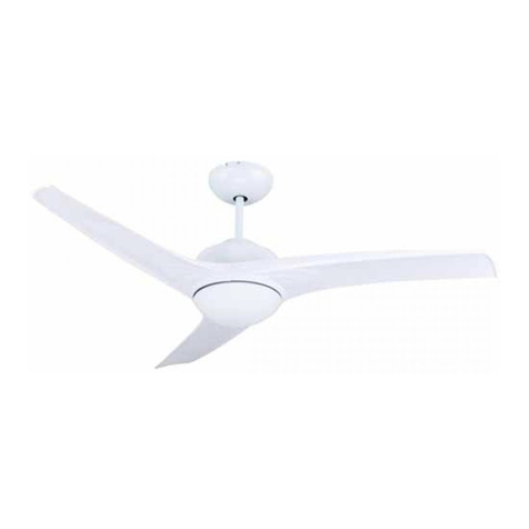
DECORATIVE CEILING FANS (VT-3042-3)
TECHNICAL DATA
1) 42" (107CM ) Decorative ceiling fan
2) With forward and reverse function
3) 3 PC Plastic blades
5) DC powerful motor:153 × 15mm, 2.3kg
6) Revolutions per minute:220±10 RPM
7) Blade angle 13°
8) 5 speeds and light remote control
9) LED 30W 3in1 CCT
10) Power:220V,50HZ,35W (motor)
11) G.W.: 9.8KG / N.W.: 9.1KG
Thank you for selecting and buying V-TAC
product. V-TAC will serve you the best. Please
read these instructions carefully before start-
ing the installation and keep this manual
handy for future reference. If you have any
another query, please contact our dealer or
local vendor from whom you have purchased
the product. They are trained and ready to
serve you at the best.
The warranty is valid for 2 years from the date
of purchase. The warranty does not apply to
damage caused by incorrect installation or
abnormal wear and tear. The company gives
no warranty against damage to any surface
due to incorrect removal and installation of the
product. The products are suitable for 10-12
Hours Daily operation. Usage of product for 24
Hours a day would void the warranty. This
product is warranted for manufacturing defects
only.
INTRODUCTION & WARRANTY

Tools and material required (not included)
1. Mounting bracket
2. Down rod
3. Canopy
4. Fan body
5. Lampshade
6. Connector
7. Screw pack
8. Remote control
9. Screwdriver
10. Flat-blade screwdriver
11. 14 wrench
12. Herringbone ladder
13. Tape Pliers
14. Electrical tape
PARTS AND COMPONENTS
1
2
3
4
5
6
7
8
10 11 12 13 14
9

IMPORTANT NOTES:
1. FAN WILL NOT START
• Check the wire connections to the fan, ensure they are all correct.
• Check and ensure the input wattage is correct to be 220V/50HZ.
2. THAN FAN SOUNDS NOISY
• Make sure all assembled screws are tight.
• Make sure wire nut connections are not rubbing against each other or the interior
wall of the switch housing.
STEP 1. MOUNTING BRACKET INSTALLATION
• Concrete ceiling: Drill two holes with an appropriate depth by a
drilling bit with dia. At 8mm, and insert two pieces expansion
screws in the holes, then fix the hanger bracket into the expand-
ing screws with the wood screws and tighten it by the nuts of the
expansion screws (Fig. 1).
• Wood ceiling: Fix the mounting bracket to the wood ceiling with
(thickness at 7cm at least) by 4 wood screws (Fig. 2).
FIG 1
FIG 2

• Get off the pin from the downrod by removing the R clip, and get the lead wire through the
downrod, canopy and the connector, then seat the downrod into the fan body & rotate the
the downrod until the holes on the downrod will match with the holes on the fan body, final-
ly, you should get the pin through the holes and fix the pin by the R clip by another side
(Fig. 3).
• Place the downrod with hanger ball into the mounting bracket, rotate the motor assemble
until the Tab" on the mounting bracket has dropped into the "Registration Slot" on the hang-
ing ball and seat firmly (Fig. 4 & 5).
FIG 3 FIG 4 FIG 5
STEP 2. INSTALLATION OF THE HANGER SYSTEM

STEP 3. WIRING DIAGRAM
FOR LIGHT L BROWN
AC IN N BLUE
AC:220-240V
AC IN L BROWN AC L
AC N
TO THE
FAN LIGHT
TO THE
FAN MOTOR
BROWN
TO FAN WIRES
TO AC POWER
AC POWER INPUT
LIGHT MOTOR
REDBLUE
BLUE
GRAYPINK
BROWN
FOR LIGHT N BLUE
MOTOR
MOTOR PINK
RECEIVER OF
REMOTE CONTROL
YELLOW GREEN
YELLOW GREEN
MOTOR GRAY
MOTOR RED
Connect 220-240V main power (dwelling) to the Terminal Block located on the hanger
bracket. Plug the receiver in the hanger bracket with the flat side facing up.
• Insert the 3P connector of hanger bracket into the AC POWER INPUT socket of receiver
• Insert the 2P light connector of fan motor assembly into the 2P LIGHT socket of receiver
• Insert the 3P motor connector of fan motor assembly into the 3P MOTOR socket of receiver
• Connect the yellow/green connectors of fan motor assembly and hanger bracket.
BROWN
BLUE
PINK
GRAY
RED
WARNING: To avoid possible
electrical shock, be sure elec-
tricity is turned off at the main
fuse box before wiring

• Make sure the key slot on the light glass is in the same line with the key slot on the fan
body, then rotate the glass clockwise slightly until the glass is firmly locked (Fig. 7 & 8).
STEP 4. INSTALL THE GLASS
Lift up the canopy to the ceiling for covering the mounting brack-
et(make sure the canopy will seat into the two screws on the
bracket), rotate the canopy to ensure the screw head are at the
narrow end of the key holes, tighten the screws (Fig. 6).
FIG 6
FIG 7 FIG 8

REMOTE CONTROL SETTING OPERATION
1. Restore electrical to the outlet box by
turning the electricity on at the main fuse
box.
2. Remove the battery cover from the
remote control transmitter, install the bat-
tery, and replace the cover.
Note:
1 ). Use 1 12V battery to replace battery.
2). If not using for long periods of time,
remove the battery to prevent damage to
the remote transmitter, and store the remote
transmitter away from excess heat or
humidity.
3. The buttons on the remote control trans-
mitter control the fan speed and light as
follows.
LIGHT ON/OFF
FAN ON/OFF
Fan Speed
1 - Highest speed
5 - Lowest speed
Reverse Function
Controls the Fan
Direction
Timer
1H-Fan auto turn
off after 1 hour
4H-Fan auto turn
off after 4 hours
8H-Fan auto turn
off after 8 hours

In case of any query/issue with the product, please reach out to us at: support@v-tac.eu For More products range,
inquiry please contact our distributor or nearest dealers. V-TAC EUROPE LTD. Bulgaria, Plovdiv 4000, bul.L.Karavelow 9B
STEP 5. BALANCE ADJUSTMENT FOR THIS "INVISIBLE" FAN
Affect during the long distance transportation. So please re-balance the fan according to the
following steps if you found the fan has got the noticeable wobble problem after your final
assembly:
• Take out the balance kit pack from the package, and stick two balance magnet pieces on any
one place marked digit shown on Figure 10, and turn on the fan to check if the wobble prob-
lem is still noticeable. Repeat this until found the place which will solve the wobble problem
(Fig.10).
• Take off the balance magnet pieces and peal a balance kit to stick on instead (Fig.11).
BALANCE
MAGNET
PIECE
BALANCE KIT
FIG 9 FIG 10 FIG 11
Table of contents
Other V-TAC Fan manuals

V-TAC
V-TAC VT-8217-3 User manual

V-TAC
V-TAC 80133970 User manual

V-TAC
V-TAC VT-5547 User manual

V-TAC
V-TAC VT-4016-3 User manual

V-TAC
V-TAC VT-6052-5 User manual

V-TAC
V-TAC VT-6042-4 User manual

V-TAC
V-TAC VT-6552-3 User manual

V-TAC
V-TAC VT-5016-5 User manual

V-TAC
V-TAC VT-4012-3 User manual

V-TAC
V-TAC VT-5536 User manual
Popular Fan manuals by other brands

Dr.Prepare
Dr.Prepare DDF-0BKDF8 user guide

Clatronic
Clatronic VL 3741 S instruction manual

Enigma
Enigma Enigma FP2120xx Series owner's manual

Broan
Broan XB110HL installation guide

Honeywell Home
Honeywell Home VNT5150H1000 Professional installation guide

Stelpro
Stelpro ULTRA QUIET Series installation guide