V-TAC VT-6605105 User manual

Single Phase On-Grid Solar Inverter
3KW
VT-6603105 SKU: 11369
5KW
VT-6605105 SKU: 11370
3KW
VT-6603110 SKU: 11379
5KW
VT-6605110 SKU: 11380
10
YEAR
WARRANTY
5
YEAR
WARRANTY
Zero Export
Function
(Optional)
External
Inductor
IP65 Natural Cooling,
Low noise Aluminum
Enclosure
5+5 Years
Warranty
70
S O LD I N O V E R
COUNTRIES
Single Phase On-Grid Solar Inverter

Max. Input Power
Max. Input Voltage
Start Voltage / Min. Operating Voltage
MPPT Voltage Range
MPPT Rated Voltage
Number of MPP Trackers / String per MPPT
Max. Current per MPPT
Input (DC)
Max. Output Current
Rated AC Power
Rated Grid Frequency
Rated Grid Voltage
Power Factor
THDi
Output (AC)
Max. Eciency
European Eciency
MPPT Eciency
Eciency
ProtectionProtection
Display
System Language
Communication
Communication
Grid Connection Standards
Safety / EMC
Standard
Compliance
Dimensions (W x H x D)
Weight
Operating Temperature Range
Cooling Method
Protection Degree
Noise
Highest Altitude
Relative Humidity
Topology
Night Power Consumption
Warranty
General Data
3.6kW
MODEL VT-6603105, VT-6603110 VT-6605105, VT-6605110
6kW
8A 12A
14A 20A
97.7% 97.8%
96.7% 96.8%
3kW 4.6kW
600V
120V / 100V
120V-550V
360V
2/1
50Hz / 60Hz
≥0.99 (Rated Power)
<3% (Rated Power)
99.9%
LED (Optional) / LCD (Standard)
Standard: RS485
IEC 61727:2004, IEC62116:2014, IEC 60068-2-1:2007, IEC 60068-2-2:2007, IEC 60068-2-14:2009,
IEC 60068-2-30:2005, IEC 61683:1999, DIN VDE 0126-1-1:2013, DIN VDE V 0124-100:2020,
VDE-AR-N 4105:2018, G98:2019, C10/11:2019, AS/NZS 4777.2:2020, NB/T 32004-2018, PEA, ZVR
IEC/EN 62109-1:2010, IEC/EN 62109-2:2011, EN 61000-6-2:2019, EN 61000-6-3:2007/A1:2011
360 x 462 x 150 mm
18kg
'-25º~+60º(Derating above 45º)
Natural Cooling
IP65
<30dB
3000m (Derating above 2000m)
0~95%
Transformerless
<1W
5years (Standard) / 10years (Optional)
English / Chinese / German / Dutch
230V, L+N+PE
DC switch, AC short-circuit protection, Over current protection, Over voltage protection,
Isolation protection, RCD, Surge protection, Anti-islanding protection, Over-temperature
protection, Ground fault monitoring, etc.
70
S O LD I N O V E R
COUNTRIES
Single Phase On-Grid Solar Inverter

INSTRUCTION MANUAL
SOLAR INVERTER
IN CASE OF ANY QUERY/ISSUE WITH THE PRODUCT, PLEASE REACH OUT TO US AT: SUPPORT@V-TAC.EU
FOR MORE PRODUCTS RANGE, INQUIRY PLEASE CONTACT OUR DISTRIBUTOR OR NEAREST
DEALERS. V-TAC EUROPE LTD. BULGARIA, PLOVDIV 4000, BUL.L.KARAVELOW 9B
Thank you for selecting and buying V-TAC Product. V-TAC will serve you
the best. Please read these instructions carefully & keep this user manual
handy for future reference. If you have any another query, please contact
our dealer or local vendor from whom you have purchased the product.
They are trained and ready to serve you at the best.
INTRODUCTION
Multi-Language Manual QR CODE
Please scan the QR code to access the manual
in multiple languages.

WARNING
1. Please make sure to turn off the power before starting the installation.
2. Installation must be performed by a qualified electrician.
3. Proper grounding should be ensured throughout the installation.
Caution, risk of
electric shock.
This marking indicates that this
product should not be disposed
of with other household wastes.
20
PAP
SAFETY PRECAUTIONS
The series grid-tied solar inverters are designed and tested strictly in accordance with
relevant international safety standards. As an electrical and electronic device, all relevant
safety regulations must be strictly complied during installation, operation, and maintenance.
Incorrect use or misuse may result in:
• Injury to the life and personal safety of the operator or other people.
• Damage to the inverter or other property belonging to the operator or other people.
In order to avoid personal injury, damage to the inverter or other devices, please strictly
observe the following safety precautions.
This chapter mainly describes various warning symbols in operation manual and provides
safety instructions for the installation, operation, maintenance and use of the series grid-tied
solar inverters.
ICONS
This manual provides relevant information with icons to highlight the physical and property
safety of the user to avoid device damage and physical injury.
The icons used in this manual are listed below:
Icons Name Instruction Abbreviation
Danger
Danger
Serious physical injury or even death
may occur if not follow the relative
requirements
Warning
Warning
Physical injury or damage to the
devices may occur if not follow the
relative requirements
Do not
Electrostatic
sensitive
Damage may occur if not follow the
relative requirements
Hot sides
Hot sides Sides of the device may become hot.
Do not touch.
Note Note The procedures taken for ensuring
proper operation.
Note

SAFETY GUIDELINES
After receiving this product, first ma ke sure that the product is well
packaged. If you have any questions, please contact the shipping
company or local distributor immediately.
Installation of PV inverters must be performed by professional
technician who has been specially trained, thoroughly read and familiar
with all the contents of this manual and familiar with the safety
requirements of the electrical system.
Do not carry out any wiring and inspection or changing components
when the power supply is applied.
Ensure that there is no electromagnetic interference from other
electrical and electronic equipment on the installation site .
Do not refit the inverter unauthorized.
All the electric installation needs to be compliance with the national or
local laws and standards.
The temperature of individual parts o r the enclosure of the inverter–
especially the heat sink may become hot in normal operation. There is a
danger of burning. Do not touch.
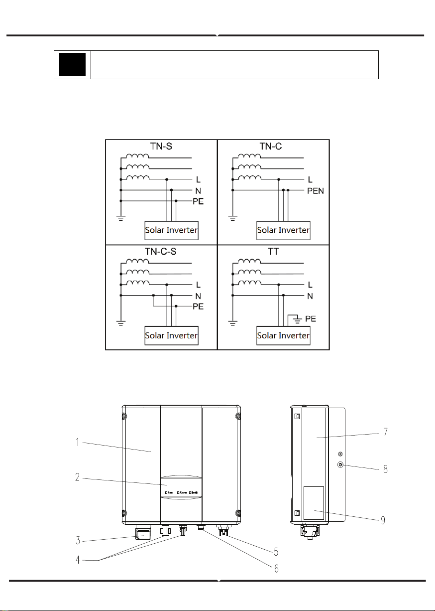
It must be reliably grounded before operation.
Do not open the cover of inverters unauthorized. The electrical parts
and components inside the inverter are electrostatic. Take
measurements to avoid electrostatic discharge during rel evant
operation.
The inverter must be reliably grounded.
Ensure that DC and AC side circuit breakers have been disconnected
and wait at least 5 minutes before wiring and checking.
Note: Technical personnel who can perform installation, wiring, commissioning,
maintenance, troubleshooting and replacement of the series grid-tied solar inverters
must meet the following requirements:
Operators need professional training.
Operators must read this manual completely and master the related safety precautions.
Operators need to be familiar with the relevant safety regulations for electrical systems.
Operators need to be fully familiar with the composition and operating principle of the
entire grid -tied photovoltaic power generation system and related standards of the
countries/regions in which the project is located.
Operators must wear personal protective equipment.

WHAT TO DO AFTER SCRAPPING
DELIVERY AND INSTALLATION
GRID-TIED OPERATION
Only qualified electricians are allowed to operate the inverter under the
permission of local power departments.
All electrical connections must meet the electrical standards of the
countries/regions in which the project is located.
Ensure reliable installation and electrical connection before operation.
Do not open the cover of inverter during operation or voltage is present.
Keep the package and unit complete, dry and clean during storage and
delivery.
Please remove and install the inverter with two or more people, because of
the inverter is heavy.
Remove and instal l the inverter with appropriate tools to ensure safe and
normal operation and avoid physical injury or death. The people also need
mechanical protective measures, such as protective shoes and work clothes.
Only qualified electricians are allowed to install the inverter.
Do not put and install the inverter on or close to combustible materials.
Keep the installation site away from children and other public places.
Remove the metal jewelry such as ring and bracelet before installation and
electrical connection to avoid electric shock.
Do cover solar modules with light-tight materials before electrical connection.
Exposed to sunlight, solar modules will output dangerous voltage.
The inverter input voltage cannot exceed the maximum input voltage;
otherwise inverter damage may occur.
The positive and negative pole of solar module s cannot be grounded,
otherwise irrecoverable damage may occur.
Ensure the proper grounding of the inverter, otherwise, improper connection
or no grounding may cause stop of the in verter.
Ensure reliable installation and electrical connection.
Do not dispose of the inverter together with household waste. The user has
the responsibility and obligation to send it to the designated organization for
recycling and disposal.

APPLICATION
The photovoltaic grid-tied power generation system consists of solar modules, grid-tied
inverter, metering devices and public grid.
Grid-tied solar inverter is the core of photovoltaic power generation system. The solar energy
can be converted into DC electric energy through solar modules and then be changed into
sinusoidal AC energy which has the same frequency and phase with the public grid by
grid-tied solar inverters, and then be fed to the grid.
The series grid-tied solar inverters are only applied in solar grid-tied power generation
system and its DC input are only composed of crystalline silicon solar modules whose
negative and positive poles are not grounded.
MAINTENANCE AND INSPECTION
SOLAR GRID-TIED POWER GENERATION SYSTEM
Only qualified electricians are allowed to perform the mainte-
nance, inspection, and components replacement of the inverter.
Contact with the local dealer or supplier for maintenance.
In order to avoid irrelevant personnel from entering the mainte-
nance area during maintenance, temporary warning labels must be
placed to warn non-professionals to enter or use fence for isolation.
Firstly disconnect all power supplies of the grid to the inverter
before any maintenance, and then disconnect the DC breakers and
wait for at least 5 minutes until the inverter is discharged before
maintenance.
Please follow electrostatic protection norms and take correct
protective measures because of the electrostatic sensitive circuits
and devices in the inverter.
Do not use parts and components not provided by our company
during maintenance.
Restart the inverter after settling the fault and problem which may
affect the safety and performance of the inverter.
Do not get close to or touch any metal conductive part of the grid
or inverter, otherwise electric shock, physical injury or death and fire
may occur. Please do not ignore the warning icons and instructions
with “electric shock”.
Figure 1 Application of the series grid-tied solar inverters

The series grid-tied solar inverters support TN-S, TN-C, TN-C-S and TT grid connection.
When applied to the TT connection, the N-to-PE voltage should be less than 30V.
SAFETY GUIDELINES
PRODUCT APPEARANCE
The recommended solar modules need to comply with IEC61730 Class A
standard.
Figure 3 Products appearance

PARTS INSTRUCTION
NAMEPLATE
Figure 4 Inverter nameplate
1. Trademark and product type
2.Model and important technical
parameters
4.Serial number, company name
and country of origin.
3.Certification system of the
inverter confirming
No. Name Instruction
1
Cover
2LED displaypanel LED indicators
3DC switch On –off of the DC input (optional)
4DC input port For the connection of solar modules
5AC terminal For the connection of AC output
6Communication port RS485 and EXT communication port
7Cooling chamber
8 Radiator
9Name plate For rated parameters and safety precautions of the inverter

PRODUCTS MODULES
Table of the grid-tied solar inverter
Product name Model
Rated output
power
Single-phase (L, N, PE)
Single-phase grid-tied solar inverter
3KW-2M 3000
5KW-2M 4600
ICONS CERTIFICATION
Icons Instruction
CE certification mark. The inverter complies with the CE directive.
EU WEEE mark. Cannot dispose of the inverter as household waste.

Model H (mm)
W
(mm)
D (mm)
Net weight
(kg)
3KW-2M / 5kW-2M
420 360 150 17
D
DIMENSIONS AND WEIGHT
Figure 5 Inverter dimensions
Table of inverter dimension and net weight
Figure 6 Paper packages dimension
Table of packages dimension and gross weight
W
H
Model H
(mm)
W
(mm)
D
(mm)
Gross
weight
(kg)
Packagin
g
Material
3KW-2M / 5kW-2M
573 480 284 19 Paper

STORAGE
If the inverter is not put into use immediately, the storage of inverter should meet the
following requirements:
• Do not remove the outer packing.
• The inverter needs to be stored in a clean and dry place, and prevent the erosion of
dust and water vapor.
• The storage temperature should be kept at -40°C~+70°C, and the relative humidity
should be kept at 5%RH~95%RH.
• The stacking of inverters is recommended to be placed according to the number of
stacking layers in the original shipment. Place the inverter carefully during stacking to
avoid personal injury or equipment damage caused by the falling of equipment.
• Keep away from chemically corrosive substances that may corrode the inverter.
• Periodic inspections are required. If damages are found by worms and rats, or packages
are found to be damaged, the packaging materials must be replaced in time.
• After long-term storage, inverters need to be inspected and tested by qualified person-
nel before put into use.
INSTALLATION
This chapter describes how to install the inverter and connect it to the grid-tied solar
system (including the connection between solar modules, public grid and inverter).
Read this chapter carefully and ensure all installation requirements are met before
installation. Only qualified electricians are allowed to install the inverter.
UNPACKING INSPECTION
The inverter has been thoroughly tested and rigorously checked before delivery, but
damage may still occur during transportation. Before unpacking, check carefully whether
the product information in the order is consistent with that on the nameplate of the
package box and whether the product package is intact. If any damage is detected,
please contact the shipping company or the supplier directly. Please also provide photos
of the damage to get our fastest and best service.
Put the inverter into the package if not used and protect it from humidity and dust.
Check as following after unpacking:
(1) Ensure no damage to the inverter unit.
(2) Ensure the operation manual, port and installation accessories in the package.
(3) Ensure no damage or loss to the items in the package.
(4) Ensure the information of the order is the same as that of the name plate.
(5) The standard delivery list is shown as below.
Single-phase inverter packing list:
Figure 7 Single-phase inverter packing list

INSTALLATION PLACE
Select installation place based on the following considerations:
(1) The height of the installation position should ensure that the line of sight is at the same
level as the LCD for viewing the parameters of inverter conveniently.
(2) Select a well ventilated place sheltered from direct sun radiation and rain.
(3) Allow sufficient space around the inverter to enable easy installation and removal from
the mounting surface and air convection. (See Figure 8).
(4) The ambient temperature of installation should be -25°C~60°C
(5) The installation site should be away from electronic devices which can generate strong
electromagnetic interference.
(6) The inverter needs to be installed on a firm and sturdy surface, such as wall and metal
bracket and so on.
(7) The installation surface should be perpendicular to the horizontal line. (See Figure 9)
(8) The installation should ensure that the inverter is reliably grounded, and the material of
grounded metal conductor should be consistent with the metal material reserved for the
grounding of the inverter.
BEFORE INSTALLATION
Installation tools
Table of detailed delivery list of single-phase inverter
NO NAME QUANTITY
13KW-2M / 5KW-2M 1
2Installation bracket 1
3
Operation manual 1
4Bolt M5*20 2
5Expansion bolts M6*60 3KW-2M / 5KW-2M
6Communication connector 1
7DC connector
3KW-2M / 5KW-2M:2 pairs
8AC connector 1
Table of tools list
NO INSTALLATION TOOLS INSTRUCTION
1Marking pen Mark the installation hole
2 Electrodrill Drill in the bracket or wall
3Hammer Hammer on the expansion bolts
4Monkey wrench Fixthe installation bracket
5Allen driver Fasten the screws, remove and install AC wiring box
6Straight screwdriver For AC wiring
7 Megger M easuring insulation performance and impedance
8 Multimeter Check the circuit and AC and DC voltage
9Electric iron Weld communications cable
10 Wire crimper Crimp DC terminals

Figure 8 Installation space
Figure 9 Installation position
Ensure there is sufficient space for heat-releasing. In generally, below space requirement
should be met:
Table of detailed installation space
M inimum clearance
Lateral 200mm
Top 450mm
Bottom 450mm
Do not open the cover of the inverter or replace any part as incomplete
inverter may cause electric shock and damag e the device during operation.

CABLE SPECIFICATION
In order to regulate and compatible with the inverter AC/DC connector or terminal block
specifications, below requirements on the AC/DC cable connected to corresponding inverter
should be fulfilled:
MINIATURE CIRCUIT BREAKERS
In order to ensure safe operation of the inverter and circuits, it is recommended to
configure corresponding micro breaker or fuse on the DC input side and AC output side
of the inverter. The below table is the requirements for recommended micro breaker:
MECHANICAL INSTALLATION
The material for fixing the inverter and the installation mode vary with the different
installation sites. It is recommended to install the inverter vertically to the firm wall or
metal bracket. Here we take wall installation as an example to introduce the installation
matters of the inverter.
As shown in the Fig 10, the overall installation of the inverter should be vertical to the
horizontal surface.
Table of cable specifications
Table of specifications of micro breaker
DC input AC output
Recommended DC breakers Recommended AC breakers
3KW-2M DC500V,C16A,2P AC240V,C20A,2P
5KW-2M DC500V,C20A,2P AC240V,C32A,2P
M odel
LN/PE
3kW-2M / 5kW-2M
4 4 6
M odel
DC side AC side
M in cross-
sectional area
mm²(length≤50m)
Min cross sectional
area mm²
(Length>50m)
M ini cross-sectional
area mm²

INSTALLATION STEPS:
(1) Firstly, take down the installation bracket from the package.
(2) Place the bracket at the appropriate height and position on the wall. Mark the punching
position according to the fixing hole. Drill holes of 70mm deep and install the expansion
screw. Fix the bracket on the expansion bolt according to the arrow instruction. Ensure the
installation is firm enough, the tightening torque is 8Nm.
(3) Lift the inverter to suspend it on the installation bracket through M8 hex socket cap
screws.
(4) Finally, fasten the inverter and the bracket with M5 screws and tighten the screws to 2
Nm. For firm installation, the operators cannot release the device until the inverter is
installed on the bracket firmly.
Table of size of installation bracket Table of instruction of installation bracket
Figure 10 Installation bracket
of 0.75~3KW inverter
Figure 11 Installation bracket
of 4~6KW inverter
INSTALLATION OF SINGLE-PHASE INVERTER
No. Structure instruction
1Installation holeΦ8
2Assembling bolt hole M 5
Installation hole
A(mm)*B(mm)
3KW-2M / 5KW-2M 260*45
M odel
Figure 12 Installation of inverter

WIRING INSTALLATION
This section describes the electrical connection related content and related safety
precautions. Figure 13 is the schematic diagram of the photovoltaic grid-connected
system.
Figure 13 PV grid-connected system diagram
Electrical connection must be carried out by professional technicians as wrong
operation may cause damage to the device, physical injuries or even death
during system operation.
All the electrical installation must conform to the national and local electrical
safety regulations.
Ensure all the cables are installed firmly according to the specified safety
requirements and free from any damage.
It is not allowed to close the AC and DC breakers before the inverter is
electrically connected.
Note
Read and follow the instructions provided in this section . Strictly follow the
requirements when operating.
Always note the rated voltage and current defined in this manual. Never exceed
the limits.

WIRING INSTALLATION
Connection steps:
(1) Lighting, short-circuit and other protection measures which meet the local electrical
safety laws and regulations are needed before the AC connection.
(2) Connect the output cables of solar modules to the DC connector of inverter as Figure
4.8 shows. Loose the nut of connector and remove the isolation layer of the DC cable for
about 8-10mm. Insert the conductor part into the appropriate position of the connector,
crimp the MC4 DC terminal of the inverter and tighten the nut with a torque of 2.5-3Nm.
The wiring of negative pole is the same as that of the positive pole. Ensure the poles of
solar modules are well connected with the connectors;
Figure 14 Connection between DC connector and solar modules
PV strings can be connected to inverter only after protection measures
which conform to local electrical regulations are taken and the technical
parameters in this manual are fulfilled.
The PV string connected to the series inverter must adopt the DC connector
configured especially for the inverter, do not use other connection devices
without authorization from our company, otherwise damage to the device,
unstable operation or fire may occur and our company will not undertake
quality assurance or assume any direct or joint liability thereof.

AC CONNECTION
(3) After the DC connector is connected,
use a multimeter to measure the
voltage of the DC input string, verify the
polarity of the DC input cable, and
ensure that the voltage of each string is
within the allowable range of the
inverter, as shown in Figure 15
(4) Connect the DC connector with the
inverter and ensure tightly-fastened;
(5) When removing the DC connector
from the inverter, insert the head of the
straight screwdriver into the raised hole
in the middle of the connector, and force
the movable end of the connector to
exit.
AC connection steps of single-phase
inverter:
(1) Before connecting the single-phase
AC grid cable to the inverter, take
lightning and short circuit protection
measures in accordance with the local
electrical safety codes;
(2) As shown in Figure 16, connect and
fasten L, N and PE conductors of the
single-phase AC grid to AC terminal and
tighten to 0.5 Nm. Assemble the AC
terminal and tighten to 2.5-3 Nm, then
connect the terminal to the AC port of
the inverter.
(3) Connect the DC output cable of the
PV module to the DC connector which
provided by our company, and then
connect the DC connector to the DC
terminal of the inverter.
Figure 15 DC input voltage measuring
Figure 16 AC connection of single-phase inverter
• Only qualified cables under the local electrical safety laws and
regulations and comply with the technical parameters of this
manual are allowed to connect to the inverter.
• Only with the permission of the local electric power company can
the inverter be connected to the utility grid.

OPERATION
INSPECTION BEFORE OPERATION
GRID-TIED OPERATION
The following items must be checked strictly before running the PV grid-connected
inverter (including but not limited to):
(1) Ensure the installation site meet the requirement mentioned in installation pace for
easy installation, removing, operation and maintenance;
(2) Ensure the mechanical installation meet the requirement mentioned in table of
installation pace;
(3) Ensure the electrical installation meet the requirement mentioned in table of cable
specifications;
(4) Ensure all switches are “off”;
(5) Ensure the open circuit voltage of the PV module complies with the DC side parameter
requirements(in the appendix) of inverter;
(6) Ensure all electrical safety precautions are clearly-identified on the installation site.
Please start the inverter as follows:
(1) Ensure the requirements mentioned in inspection before operation are met;
(2) Switch on the breakers at the AC side;
(3) Switch on the integrated DC switch;
(4) Switch on the switch on the DC side;
(5) Observe the LED indicator state of the inverter and the information displayed by LCD.
Refer to chapter 6 for LED state indicator and LCD display information.
In order to ensure a safe, normal and stable operation of the PV power
generation system, all the newly installed, renovated and repaired PV grid -
connected power generation system and its grid -connected inverter must
undergo inspection before running.
Start the inverter according to below steps to achieve grid-connected operation of the
inverter:
Note Note
Must to select the country to set grid-connected standard during the initial
operation of the inverter
Keep the power-on state of the inverter for at least 30 minutes, and complete
the charging of built-in clock battery of the inverter to ensure the clock can run
normally!
Run
Green indicator flickers, other indicators are off: Inverter is powered on and
under self-inspection, wait for enough light to fulfill grid -connected condition;
Run
Green indicator on, others off : The inverter is in power generation after self-
inspection----successful commissioning.
“Warn” or “Fault” indicator is on or flickers: inverter is powered on but system fault
occur. Refer to LCD screen to check the fault code in LCD display, stop the inverter as per
STOPPING, and rule out faults according to TROUBLESHOOTING. After all the faults are
removed, repeat the operations
This manual suits for next models
7
Table of contents
Other V-TAC Inverter manuals

V-TAC
V-TAC 23070 User manual

V-TAC
V-TAC 11381 User manual

V-TAC
V-TAC AF6K-SL User manual

V-TAC
V-TAC 11583 User manual

V-TAC
V-TAC VT-66036103 User manual

V-TAC
V-TAC SUN-5K-SG04LP3-EU User manual

V-TAC
V-TAC 80133970 User manual

V-TAC
V-TAC VT-6608303 User manual

V-TAC
V-TAC 11514 User manual

V-TAC
V-TAC VT-6607105 User manual

V-TAC
V-TAC iMars XG100KTR User manual

V-TAC
V-TAC VT-11024-4G User manual

V-TAC
V-TAC VT-6605103 User manual

V-TAC
V-TAC VT-6607136 User manual

V-TAC
V-TAC Deye SUN-8K-SG01LP1-EU User manual

V-TAC
V-TAC 11390 User manual

V-TAC
V-TAC VT-6607036 User manual

V-TAC
V-TAC VT-6605305 User manual

V-TAC
V-TAC VT-6605305 User manual

V-TAC
V-TAC SUN-6K-SG05LP1-EU User manual