V-TAC VT-6607036 User manual

INSTRUCTION MANUAL
ON-GRID PV INVERTER
INTRODUCTION
Thank you for selecting and buying V-TAC product. V-TAC will serve you the best. Please read these instruc-
tions carefully before starting the installation and keep this manual handy for future reference. If you have any
another query, please contact our dealer or local vendor from whom you have purchased the product. They
are trained and ready to serve you at the best. The warranty is valid for 5 years from the date of purchase. The
warranty does not apply to damage caused by incorrect installation or abnormal wear and tear. The company
gives no warranty against damage to any surface due to incorrect removal and installation of the product.
This product is warranted for manufacturing defects only.
MULTI-LANGUAGE MANUAL QR CODE
Please scan the QR code to access the manual in
multiple languages.
WEEE Number: 80133970
IN CASE OF ANY QUERY/ISSUE WITH THE PRODUCT, PLEASE REACH OUT TO US AT: SUPPORT@VTACEXPORTS.COM
FOR MORE PRODUCTS RANGE, INQUIRY PLEASE CONTACT OUR DISTRIBUTOR OR NEAREST
DEALERS. V-TAC HOUSE, KELPATRICK ROAD, SLOUGH, BERKSHIRE, SL1 6BW, UK
MODEL VT-6607036
SKU 11726

WARNING
Circuit Breaker Recommendation
Surge Protector Recommendation
EXPLANATION OF SYMBOL
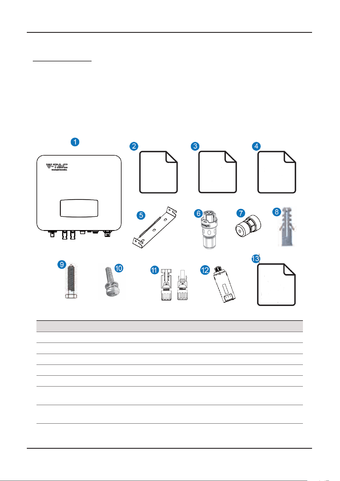
Note:
1. Please make sure to turn o the power before starting the installation.
2. Installation must be performed by a qualified electrician.
VTAC inverter strictly comply with relevant safety standards. Please read and follow all the instructions and cau-
tions during installation, operation and maintenance.
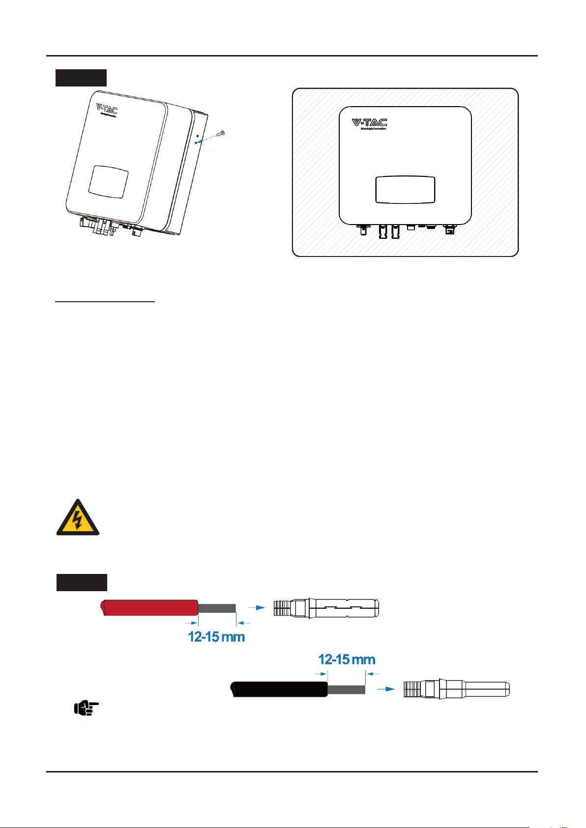
SAFETY PRECAUTIONS
1. All work on the inverter must be carried out by qualified electricians.
2. The device may only be operated with PV panels.
3. The PV panels and inverter must be connected to the ground.
4. Do not touch the inverter cover until 5 minutes aer disconnecting both DC and AC power supply.
5. Do not touch the inverter enclosure when operating, keep away from materials that may be aected by high
temperatures.
6. Please ensure that the used device and any relevant accessories are disposed of in accordance with appli-
cable regulations.
7. VTAC inverter should be placed upwards and handled with care in delivery. Pay attention to waterproof. Do
not expose the inverter directly to water, rain, snow or spray.
8. Alternative uses, modifications to the inverter not recommended. The warranty can become void if the in-
verter was tampered with or if the installation is not in accordance with the relevant installation instructions.
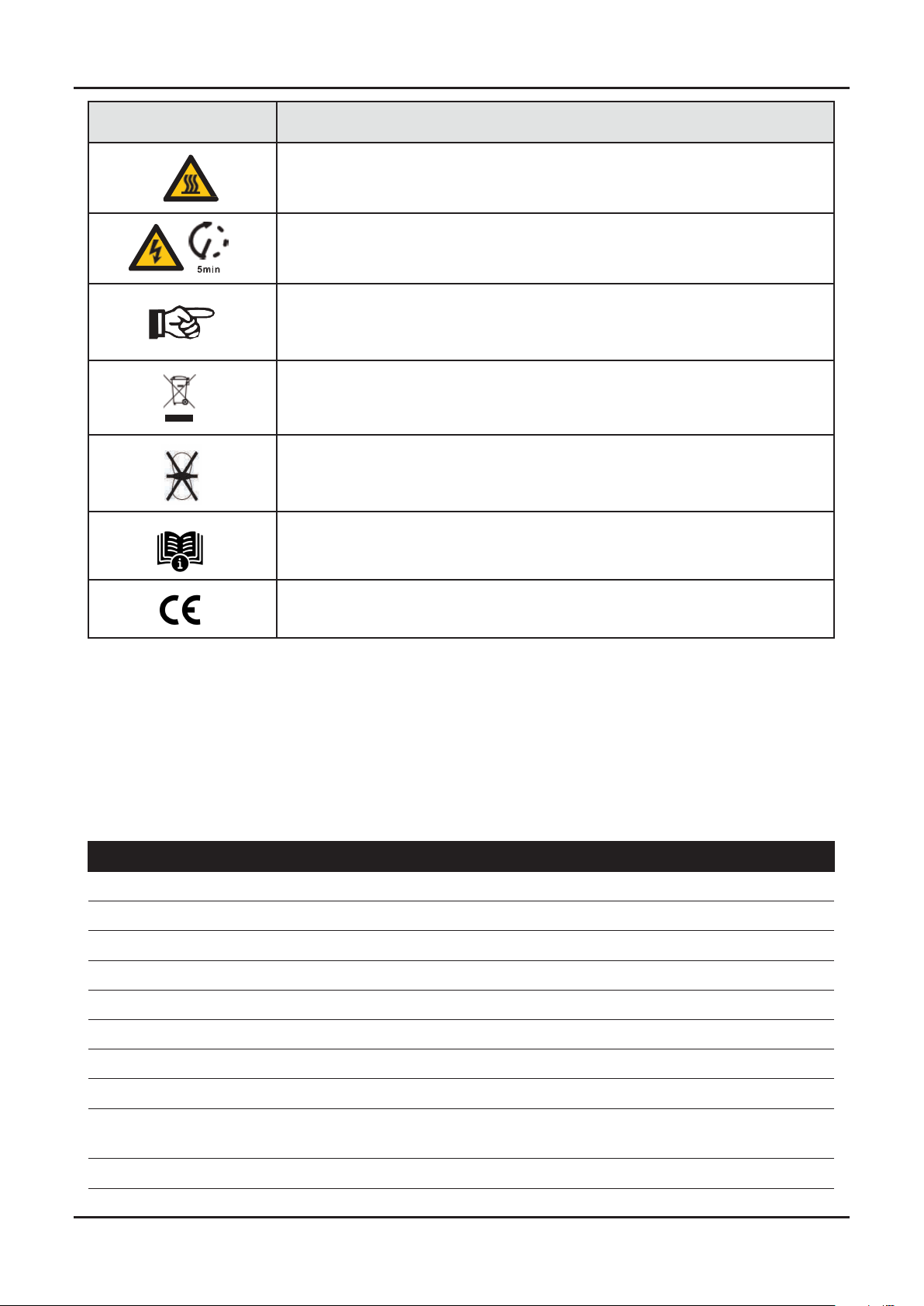
SYMBOL EXPLANATION
Danger of electric shock
The inverter contains fatal DC and AC power. All work on the inverter must be
carried out by qualified personnel only.
The Inverter can be only connected to low-voltage grid.
(220/230Vac, 50/60Hz).
TYPE MAX AC CURRENT (A) RATED CURRENT AC BRACKER (A)
Single Phase Ongrid Inverter
VT-6607036 18 25
• AC side, nominal discharge current 20KA, second grade lightning protection, protection voltage
2.5KV.
• DC side, nominal discharge current 20KA, second grade lightning protection, protection voltage
3.2KV.
• The wiring distance between the inverter and the distribution box should be at least 5 meters.

SYMBOL EXPLANATION
Beware of hot surface
The inverter’s housing may reach uncomfortably hot 60°C (140°F) under high
power operation. Do not touch the inverter enclosure when operation.
Residual power discharge
Do not open the inverter cover until 5 minutes aer disconnection both
DC and AC power supply.
Important notes
Read all instructions carefully. Failure to follow these instructions,
warnings and precautions may lead to device malfunction or damage.
Do not dispose of this device with the normal domestic waste.
Without transformer
This inverter does not use transformer for the isolation function.
Refer to manual before service.
CE mark
The inverter complies with the requirements of the applicable CE guidelines.
SPECIFICATIONS
PV INPUT DATA VT-6607036
Max. DC Power ( W ) 5400
Max. DC Voltage ( V ) 600
MPPT Voltage Range ( V ) 70-550
MPPT Full Power Voltage Range ( V ) 130-550
Rated Input Voltage ( V ) 360
Start-up Voltage ( V ) 70
Max. Input Current ( A ) 14 x 2
Max. Short Current ( A ) 18 x 2
No. of MPP Tracker /
No. of PV String 2/2
Input Connector Type MC4

AC OUTPUT DATA VT-6607036
Max. Output Power ( W ) 3960
Nominal Output Power ( W ) 3600
Max. Output Current ( A ) 17.5
Nominal Output Voltage ( V ) L/N/PE, 220Vac, 230Vac, 240Vac
Grid Voltage Range 180Vac-276Vac (According to local standard)
Nominal Output Frequency ( Hz ) 50/60
Grid Frequency Range 45~55Hz/54~66Hz
(According to local standard)
Output Power Factor 1 default (adjustable from 0.8 leading to 0.8 lagging)
Output Current THD <3%
EFFICIENCY VT-6607036
Max. Eciency 98.20%
Euro Eciency 97.82%
PROTECTION VT-6607036
PV Reverse Polarity Protection Yes
PV Insulation Resistance Detection Yes
AC Short Circuit Protection Yes
AC Over Current Protection Yes
AC Over Voltage Protection Yes
Anti-Islanding Protection Yes
Residual Current Detection Yes
Over Temperature Protection Yes
Integrated DC switch Yes
Surge Protection Integrated (Type III)
GENERAL DATA VT-6607036
Dimensions (W x H x D, mm) 358 x 360 x 142
Weight ( kg ) 10
Protection Degree IP65

Portal Web
`
Cloud Server
PV Array
AC Grid
PV Inverter
Circuit Breaker 3
PV Array
Circuit
Breaker 1 Surge Protective
Device Surge Protective
Device
Surge Protective
Device
Circuit
Breaker 1
Porta Smart-Phone
INTRODUCTION
System Diagram
The typical on-grid PV system conection diagram.
Enclosure Material Aluminum
Ambient Temperature Range ( ) -25 ~ +60°C
Humidity Range 0-100%
Topology Transformerless
Communication Interface RS485 / WiFi / Wire Ethernet / GPRS (optional)
Cooling Concept Convection
Noise Emission ( db ) <28
Night Power Consumption ( W ) <1
Max. Operation Altitude ( m ) 4000
CERTIFICATIONS AND STANDARDS VT-6607036
EMC Standard EN/IEC 61000-6-2, EN/IEC 61000-6-3, EN61000-3-2,
EN61000-3-3, EN61000-3-11, EN61000-3-12
Safety Standard IEC 60068, IEEE1547,EN62109
Grid-connection
EN50549-1, EN50438, RD 1699,UNE 217001, RD 413,
IEC61727, IEC62116, IEC61683, VDE4105,
UL1741 VDE0126 AS4777.2 NB/T 32004-2018, UNT C
15-712-1, ABNT NBR 16149, ABNT NBR 16150

Warrenty
Card
INSTALLATION
Pre-installation
Unpacking
On receiving the inverter, please check to make sure the packing and all components are not miss-
ing or damaged. Please contact your dealer directly for supports if there is any damage or missing
components.
Package List
Open the package, please check the packing list shown as below.
Unpacking & Package List
Quick
Installation
Insructions
Monitor
Quick
Installation
Instructions
No. Qty Items No. Qty Items
1 1 Solar inverter 8 3 Plastic Expansion Tube
2 1 Certificate Of Inspection 9 3 Tapping Screw
3 1 Quick Installation Instructions 10 1 Security Screw
4 1 Warranty Card 11 2DC Connector sets
5 1 Wall Mounting Bracket 12 1 Monitor Module
6 1 AC Connector 13 1 Monitoring Quick Installation In-
structions
7 4 Zero-Injection Connector
(Optional)
Certificate
Of Inspection

Product Overview
Inverter Terminals
No. Items No. Items
1DC Switch 5Monitor Module Port
2DC Connectors ( + ) For PV Strings 6Zero-Injection Port (Optional)
3DC Connectors ( − ) For PV Strings
4AC Connector

Mounting Location
The inverters are designed for indoor and outdoor installation (IP65), to increase the safety, per-
formance and lifespan of the inverter, please select the mounting location carefully based on the
following rules:
• The inverter should be installed on a solid surface, far from flammable or corrosion materials,
where is suitable for inverter’s weight and dimensions.
• The ambient temperature should be within -25°C ~ 60°C (between -13 °F and 140°F).
• The installation of inverter should be protected under shelter. Do not expose the inverter to direct
sunlight, water, rain, snow, spray lightning, etc.
• The inverter should be installed vertically on the wall, or lean back on plane with a limited tilted
angle. Please refer to below picture.

Mounting
STEP 1
STEP 2
• Leave the enough space around inverter, easy for accessing to the inverter, connection points
and maintenance.

STEP 3
Electrical Connection
Warning:
Note:
The fatal high voltage may on the DC side, please comply
with electric safety when connecting.
Please make sure the correct polarity of the cable connected
with inverter, otherwise inverter could be damaged.
PV cable suggestion
Cross-section
4mm²
The inverter is equipped with 2 MPPT channels, each of which contains a PV string input.
For the best results, make sure that each MPPT channel is correctly connected with PV string. Other-
wise, the inverter will activate voltage or current protection automatically.
Please make sure below requirements are followed:
• The open-circuit voltage and short-circuit current of PV string should not exceed the reasonable
range of the inverters.
• The isolation resistance between PV string and ground must exceed 10 kΩ.
• The polarity of PV strings are correct.
• Use the DC plugs in the accessory.
• The lightning protector should be equipped between PV string and inverter.
• Disconnect all of the PV (DC) switch during wiring.
STEP 1
Security Screw
PV Connection

STEP 2
Negative Crimp Contact
Note:
Note:
You’ll hear click sound when the connector assembly is correct.
Please use PV connector crimper to pinch the point of the arrow.
Positive Crimp Contact
STEP 3
Note:
PV String suggestion

STEP 1
Correct Installation
Grid Connection
Correct Installation
Channel A and B connected with PV strings separately
The external AC switch should be installed between inverter and grid to isolate from grid. Please
make sure below requirements are followed before connecting AC cable to the inverter.
• The AC (grid) voltage should not exceed the reasonable range of the inverters.
• The phase-line from AC distribution box are correctly connected.
• Use the AC plugs in the accessory.
• The surge protector should be equipped between grid and inverter.
• Disconnect the AC (grid) switch during wiring.
PV Array 1
PV Array 1
PV Array 2
PV Array 2
PV Inverter
PV Inverter
Warning:
The fatal high voltage may on the AC side, please comply with
electric safety when connecting.
Please make sure the right line of AC grid connected with inverter,
otherwise inverter could be damaged.
Note:
PV cable suggestion
Cross-section
4mm²

STEP 2
STEP 3
STEP 4
1. Connect AC terminals and waterproof
head, tighten the cap, make sure they clip
closely together.
2. Connect AC connector to AC terminal of
the inverter.
3. Afeer making sure that it is firmly insered,
tighten the sleeve on the AC connector to
the right and hear a click.
Note:
AC line goes through AC terminal waterproof head and cap
Connect AC line, Live line (L), Neutral line (N) and Ground Wire (PE) according to polarity.

Communication Connection
Install the WIFI / Ethernet / GPRS / RS485 Communication
The monitoring module could transmit the data to the cloud server, and display the data on the PC,
tablet and smart-phone.
WIFI / Ethernet / GPRS / RS485 communication is applicable to the inverter.
Please refer to “Communication Configuration Instruction” for detailed instruction.
STEP 1
STEP 2

Zero-injection Smart Meter (Optional)
Smart meter is an intelligent control equipment which is used for on-grid inverters. Its main function
is to measure the forward and reverse power on the grid-connected side, and transmit data to the
inverter through RS485 communication to ensure that the power of the inverter is less than or equal
to the user’s home load, and no current flows into the grid.
STEP 1
STEP 1
Note:
Note:
For single-phase inverter, please follow below pin order
RS485A(Pin 7) to single-phase meter (Pin 24)
RS485B(Pin 8) to single-phase meter (Pin 25)
Please refer to “Zero InjectionSmart Meter Installation andOperation
Manual” for detailed instruction.

Note:
The Inverter could be connected in parallel with Smart Meter,
make sure the total load power not exceed Smart Mater’s limitation.
Operation
Control Panel
No. Items No. Items
1 LCD Display 5 ENT Touch Button
2UP Touch Button 6 POWER LED Indicator
3DOWN Touch Button 7 GRID LED Indicator
4ESC Touch Button 8 FAULT LED Indicator
Weather Station
Cloud Server
PV Array
PV Inverter
PV Inverter
PV Inverter
Load
Grid
PV Array
PV Array
Router
RS485/WiFi/Ethernet/GPRS Smart Meter Energy Meter

SIGN POWER COLOR EXPLANATION
POWER
ON Green The inverter is stand-by
OFF The inverter is power o
GRID
ON Green The inverter is feeding power
OFF The inverter is not feeding power
FAULT
ON Red Fault occurred
OFF No fault
Menu Structure
First Level Menu
Second Level Menu
Three Level Menu

SETTING
Startup
Voltage Range
Explanation of LCD Display Content
NOUNS EXPLANATION
Inverter Info Display the serial number and firmware version of inverter
Error Record Check the error list of inverter including date and time
Wifi Info Display the WIFI serial number and assigned IP address
Date & Time Set date and time of the inverter
Setting Set the protection parameters of inverter
Function Enable Countercurrent power switch
Zero Injection Meter switch
UP/DOWN
Selection Date & Time
UP/DOWN Adjust the time and
Press ENT to confirm
UP/DOWN
Choose Setting UP/DOWN
Choose Volt Range

Frequency Range
UP/DOWN
set protection time
UP/DOWN Set Level 2
voltage upper limit protection
UP/DOWN set protection time
press ENT to confirm
UP/DOWN set level 2
voltage lower limit
UP/DOWN
set protection time
UP/DOWN set level 1
voltage upper limit protection
UP/DOWN
set protection time
UP/DOWN set level 1
voltage lower limit
UP/DOWN
Choose PassWord:xxxx
UP/DOWN
choose Setting
UP/DOWN
choose Freq Range
UP/DOWN
choose PassWord:xxxx
UP/DOWN
set protection time
UP/DOWN set level 2
frequency upper limit protection
UP/DOWN set protection time
press ENT to confirm UP/DOWN set level 2
frequency lower limit UP/DOWN
set protection time
UP/DOWN
set protection time UP/DOWN set level 1
frequency lower limit
UP/DOWN set level 1
frequency upper limit protection
Note:
The parameters setting only works aer the inverter is restarted.

Shut down
Maintenance
Trouble Shooting
Restart
Commissioning
Start-up & Shut Down
Maintenance&Trouble Shooting
Before starting up commissioning at site, please make sure below procedures and requirements are
fully meet.
• Mounting location is meet the requirements.
• All of the electrical wiring is firmly connected, including PV wiring, Grid wiring and Earth wiring.
• The inverter setting has been finished accordingly to local standards or regulations.
Commissioning Procedures
• Turn on the AC switch between inverter output and the public grid;
• Turn on the DC switch on the inverter;
• Turn on the PV switch of the system.
• Turn o the DC switch on the inverter.
• Turn o the DC switch between PV panels and the inverter (if any).
• Close the AC switch between the inverter and the public grid.
• Periodically maintenance are necessary, please follow steps as below.
• PV connection: twice a year
• AC connection : twice a year
• Earth connection: twice a year
• Heat sink: clean with dry towel once a year.
• Shut down the inverter according to Chapter 7.1.
• Start-up the inverter according to Chapter 6.
Note:
The inverter will be operable aer minimum 5 minutes.
Fault messages will be displayed when fault occurs, please according to trouble- shooting table find
related solutions.
This manual suits for next models
1
Table of contents
Other V-TAC Inverter manuals

V-TAC
V-TAC 80133970 User manual

V-TAC
V-TAC 23070 User manual

V-TAC
V-TAC VT-6605305 User manual

V-TAC
V-TAC 11834 User manual

V-TAC
V-TAC SUN-5K-SG04LP3-EU User manual

V-TAC
V-TAC Deye SUN-8K-SG01LP1-EU User manual

V-TAC
V-TAC VT-6605103 User manual

V-TAC
V-TAC VT-11024-4G User manual

V-TAC
V-TAC iMars XG100KTR User manual

V-TAC
V-TAC VT-66036103 User manual

V-TAC
V-TAC 11514 User manual

V-TAC
V-TAC VT-6605305 User manual

V-TAC
V-TAC 11381 User manual

V-TAC
V-TAC VT-6605105 User manual

V-TAC
V-TAC VT-66036103 User manual

V-TAC
V-TAC AF6K-SL User manual

V-TAC
V-TAC VT-6608303 User manual

V-TAC
V-TAC 11583 User manual

V-TAC
V-TAC VT-6607005 User manual

V-TAC
V-TAC VT-66036103 User manual