manuals.online logo
Brands
  1. Home
  2. •
  3. Brands
  4. •
  5. VADDIO
  6. •
  7. Security System
  8. •
  9. VADDIO WallView HD1 CCU with HSDS Owner's manual

VADDIO WallView HD1 CCU with HSDS Owner's manual

©2008 Vaddio – All Rights Reserved. Reproduction in whole or in part without written permission is prohibited. Vaddio, EZIM, HSDS,
ProductionVIEW, Quick-Connect, WallVIEW, PowerRite, are registered trademarks of Vaddio. All other trade marks are property of
their respective owners. Document Number 101708 Rev C.
W
WA
AL
LL
LV
VI
IE
EW
W™
™
C
CC
CU
U
H
HD
D1
1
W
WI
IT
TH
H
H
HS
SD
DS
S™
™
Featuring the Vaddio™ Quick-Connect™ CCU
The Vaddio WallVIEW CCU HD1 is built around the
Sony® EVI-HD1 high definition pan/tilt/zoom camera.
With a 2 mega-pixel CMOS sensor, the EVI-HD1 is an
ideal choice for a wide range of high definition video
applications. WallVIEW CCU HD1 allows the user to
adjust color, gain and iris functions of the camera (see
Figure 1). These controls allow the camera to deliver a
more accurate representation of the image that is being
captured. The other added advantages include the ability
to color match multiple cameras and make necessary
changes to iris and gain quickly and easily. Settings may
be stored by using two Scene buttons, for various lighting
conditions.
The WallVIEW CCU HD1 uses high speed differential
signaling (HSDS), an active video transmission system, to
deliver high quality HD or SD video over standard Cat. 5
cabling. Adjustments allow the video to be extended up
to 500 feet from the Quick-Connect CCU with virtually no
loss in video quality.
Overall, the WallVIEW CCU HD1 is superb for a wide range of high definition shooting applications. It is also
highly suitable for applications where adjusting the color and brightness levels of one or multiple cameras is
critical, such as houses of worship, corporate boardrooms, live event production and distance-learning
applications.
WHAT’S INCLUDED
•Sony EVI-HD1 High Definition PTZ Camera
(1/3 Type, 2 megapixel CMOS sensor with
10x zoom lens)
•EZCamera Interface Module CCU (EZIM)
•Vaddio EZIM HD Break-out Cable*
•Vaddio Quick-Connect CCU (QCCU) 1-RU
Rack Mount Interface
•Sony IR Remote
•EZCamera Control Adapter (RJ-45 to DB-9)
•36V PowerRite™ Power Supply
•Vaddio Thin Profile Wall Mount HD1
•Mounting Hardware & Documentation
* Optional EZIM SD Break-out Cable sold separately
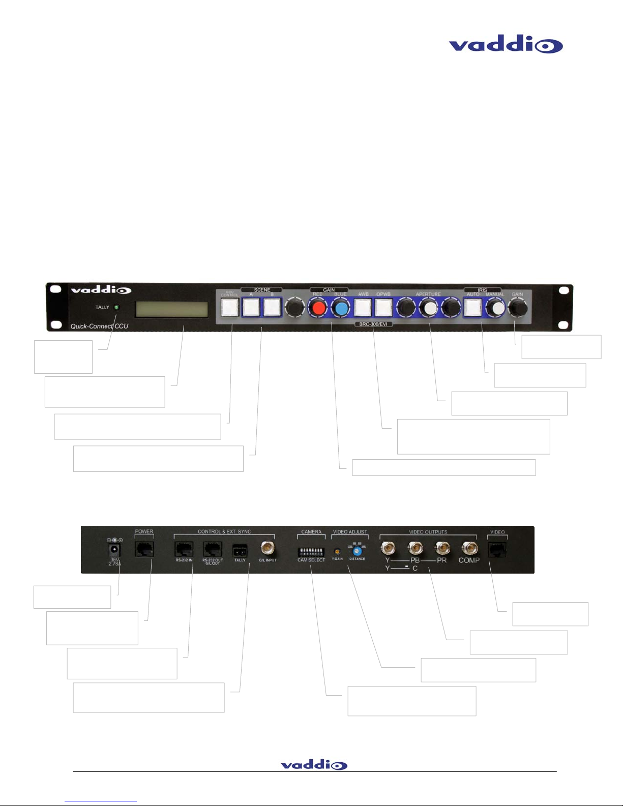
TECHNICAL FEATURES
CCU Controls
CCU controls on the product include: Red &
Blue Gain; Aperture; Auto & Manual Iris; Gain;
Auto & One Push White Balance; and Scene
Store A & B buttons.
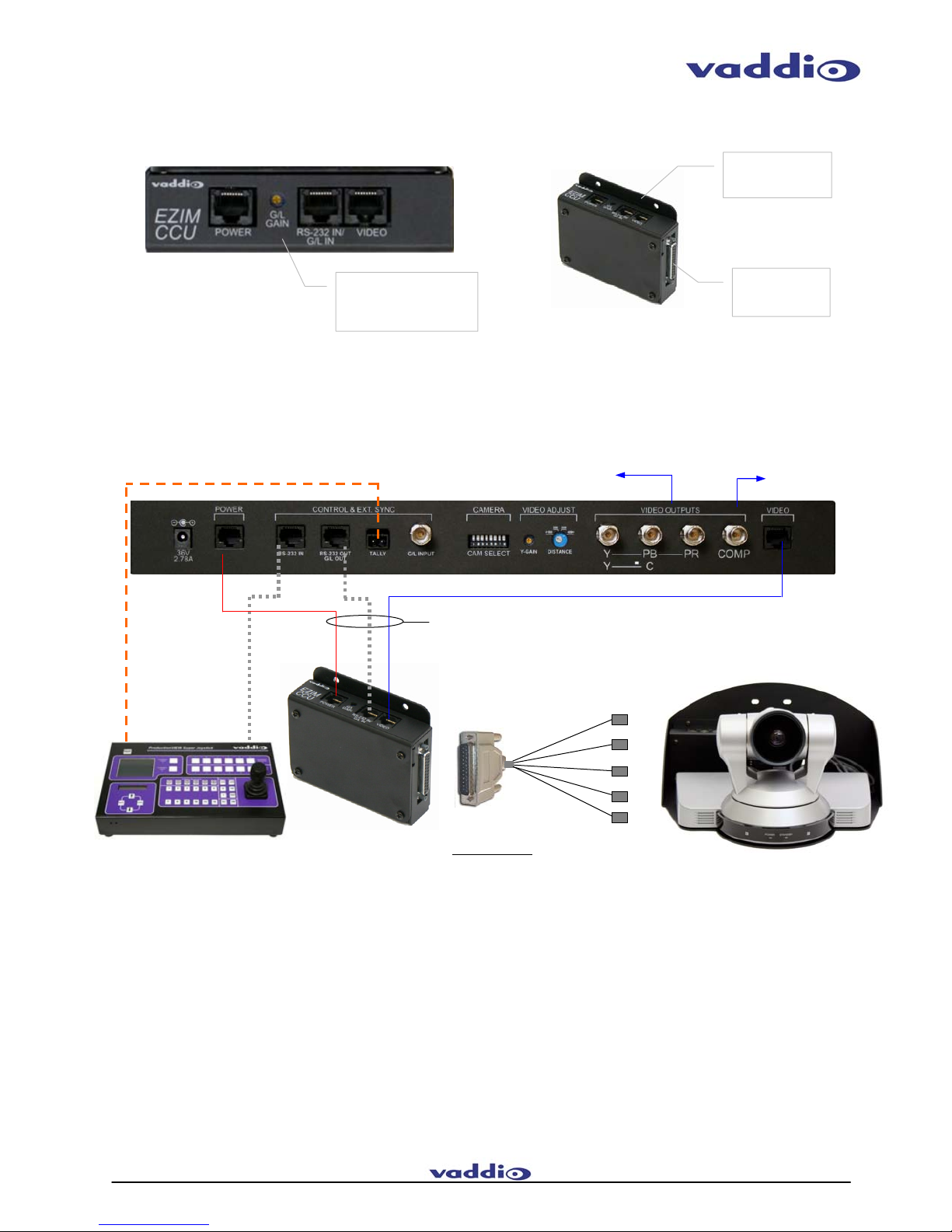
EZCamera Interface Module (EZIM)
The EZCamera Interface Module CCU is a small
camera interface module that mounts inside the
wall mount and is a universal interface for several
HD or SD PTZ cameras available today. The
EZIM uses a multi-pin connector and cable
assemblies for maximum flexibility.
Quick-Connect CCU
The 1-RU interface has (high definition) analog
component video outputs (Y, Pb, Pr) for 1080i
and 720p resolution signals or S-Video and
Composite Video* outputs on BNC connectors.
* Optional SD cable sold separately
Distance Adjustments
Because WallVIEW CCU uses active electronics,
there are four cable length adjustments (<100’,
200’, 300’ 400’+), which equalize the length of
the Cat. 5 twisted pairs and vastly improves the
HD video performance.
Figure 1: (top) Quick-Connect CCU 1 RU rack mount
interface; (bottom) WallVIEW Universal PRO HD1 System
with Camera, EZIM and Wall Mount
WallVIEW CCU HD1
Toll Free 800-572-2011 ●Phone 763-971-4400 ●FAX 763-971-4464 ●www.vaddio.com
TECHNICAL FEATURES (CONTINUED)
Luminance Gain Adjustment
A luminance gain control (Y-Gain) is also
provided, which allows for enhanced control and
fine tuning of the video signals when longer Cat.
5 cabling runs are required.
Superior Power Regulation
The WallVIEW Universal PRO HD1 uses the
PowerRite 36V power supply, which is the key to
providing the electrical current that the larger
PTZ camera motors, like the BRC-H700 or EVI-
HD1, require to operate properly.
Complete System
The WallVIEW CCU HD1 comes complete and
includes everything the installer needs to
accomplish a professional installation. Three Cat.
5 cable runs for Power, Video and Control are
required to complete the installation. .
Optional SD Break-out Cable: Part # 440-6207-000
(provides Y-C and Composite video)
TECHNICAL DRAWINGS
Figure 2: Quick-Connect CCU (QCCU) interface front panel and rear panel diagrams with functional callouts.
For PowerRite 36
VDC 2A Power Supply
POWER RJ-45 Cat. 5 cable
dedicated to supply power
to camera
CONTROL RJ-45 Cat. 5 cable,
which passes RS-232 commands
through CCU to the PTZ camera
CAM SELECT is an 8-position dip switch
that allows the user to select which
camera is connected to the CCU
Video Adjustments for Y-Gain and
Distance (up to 500’)
HD / SD Outputs on BNC
Connectors
RJ-45 for HD / SD
Video Signals
Tally & Gen Lock Inputs to for sending Tally and
Gen Lock signals to the BRC series cameras over
CAT-5 cable
Tally Light
indicates when
camera is live
Two-Line LCD Screen displays when
CCU Control is active, and the value
of the parameter that is being adjusted
CCU Control transfers RS-232 control between an
external controller (i.e. ProductionVIEW) and CCU
Scenes A & B allow manual settings of color, iris and
other parameters to be stored in QCCU
Red & Blue Gain knobs for adjusting the camera’s color levels
Auto White Balance (AWB) and One Push White
Balance (OPWB) allow the user to select either of
these modes, or manual by adjusting knobs
Aperture allows sharpness of the
video image to be adjusted
Auto and Manual Iris
settings for light intake
Gain adjustment for
camera light sensitivity
WallVIEW CCU HD1
Toll Free 800-572-2011 ●Phone 763-971-4400 ●FAX 763-971-4464 ●www.vaddio.com
SYSTEM CONNECTIVITY
Cat. 5 Cables Up to 500’
High Speed Differential Signaling
HD Video to
Switcher/Display
Figure 4:
Basic system connectivity of a WallVIEW CCU HD1 System and ProductionVIEW Super Joystick Controller
Vaddio ProductionVIEW™
Su
p
er Jo
y
stick
RS-232
RJ-45 Connectors for Video,
Power, Control and Genlock
Gain adjustment (for use on
BRC PTZ cameras)
DB-25 Connector
for Camera
Break-out Cable
Mounting Flange for
securing the EZIM
to camera mounts
EZIM ISO View
Vaddio HD Interface
Cable for WallVIEW HD1
DB-25M
4
3
2
1
EVI-HD1 on Wall
Mount with EZIM
Figure 3: EZCamera Interface Module CCU (EZIM) with three (3) RJ-45 connectors for POWER, RS-232 IN / GEN LOCK and VIDEO
(HD or SD), Top View (left) and Isometric View (right)
SD Video (in SD mode)
to Switcher/Display
Connector List
1 Y Pb Pr OUT (DB-15HD)
2 RS-232 IN (8-Pin Min Din)
3 GEN LOCK IN (unused with HD1)
4 VIDEO OUT (BNC) use in SD mode only
5 POWER
(
EIAJ4
)
5
WallVIEW CCU HD1
Toll Free 800-572-2011 ●Phone 763-971-4400 ●FAX 763-971-4464 ●www.vaddio.com
TECHNICAL SPECIFICATIONS
WallVIEW CCU HD1
Part Numbers WallVIEW CCU HD1 999-6307-000 (NTSC)
WallVIEW CCU HD1 999-6307-001 (PAL)
•Sony EVI-HD1
Image Device 1/3 type CMOS
Video Signal 1080i/59.94, 1080i/50, 720p/59.94, 720p/50, NTSC (LB, CR, SQ) or PAL (LB, CR, SQ) (switchable)
Effective Picture Elements 2 Megapixels (approximately)
Lens 10x Optical Zoom (40x with digital zoom)
Focal Length f=3.4 to 33.9mm
Horizontal Viewing Angle 8 to 70 degrees
Video S/N Ratio 50 dB
Pan/Tilt Angle -100 to +100 degrees (Pan), -25 to +25 degrees (Tilt)
•Quick-Connect CCU Interface (QCCU)
Connectors Power Connector: 5.5mm OD x 2.5mm ID
Power RJ-45: Supplies 36V to EZCamera Interface Module Regulator
Control In RJ-45: Accepts RS-232 from ProductionVIEW or other non-daisy-chain control systems
Control Out RJ-45: Passes RS-232 and Sync video feed to camera EZIM
Tally: 2-Pin Phoenix type spring cage connector
Video Inputs: BNC Connector for Sync (not applicable with HD1)
Video Outputs: BNC Connectors for HD Analog Component (Y,PB,PR) / SD (Y-C and Composite)
Video RJ-45: Transports HD video from camera EZIM
Camera Select Switch Selection switch for camera that will be operated with the CCU
Video Adjustments Y-Gain (luminance gain) for fine tuning over longer cable distances
Distance Compensation: 100’, 200’, 300’, 400’+
Cat. 5 Cable Distance Up to 500’ (152.4m)
Power Supply 36 VDC, 2 Amp
Dimensions 1-RU Rack Mount - 1.75” H x 19” W x 6” D (4.45 cm x 4.26 cm x 15.24 cm)
•EZCamera Interface Module CCU (EZIM)
Connectors Three (3) RJ-45 Connectors
One DB-25 for Power, Video, Control & Gen Lock (n/a for HD1 camera)
Cable Assembly For Sony HD1 Camera: DB-25M to DB-15HD/8-Pin Mini Din/BNC x 2/EIAJ4 Power Connector
* Optional SD Video Cable (with S-video and composite) Part # 440-6207-000
Power Regulator Supplies 12VDC to Cameras
Dimensions 3” H x 4.5” W x 1.2” D (7.6 cm x 11.4 cm x 3 cm)
•Thin Profile Wall Mount HD1
Materials 12-Gauge CRS with Black Powder Coat Paint
Dimensions 6” H x 11.75” W x 11” D (15.2 cm x 29.85 cm x 27.9 cm)
Weight 5.4 lbs. (2.5 kg)

Other VADDIO Security System manuals

VADDIO CCU 300 User manual

VADDIO

VADDIO CCU 300 User manual

VADDIO 999-1701-100 User manual

VADDIO

VADDIO 999-1701-100 User manual

VADDIO WALLVIEW CCU H700 User manual

VADDIO

VADDIO WALLVIEW CCU H700 User manual

VADDIO WIDESHOT WALLVIEW SR User manual

VADDIO

VADDIO WIDESHOT WALLVIEW SR User manual

VADDIO 999-60210-000 User manual

VADDIO

VADDIO 999-60210-000 User manual

VADDIO 999-60210-000 User manual

VADDIO

VADDIO 999-60210-000 User manual

VADDIO EasyIP Systems User manual

VADDIO

VADDIO EasyIP Systems User manual

VADDIO WallView User manual

VADDIO

VADDIO WallView User manual

VADDIO Zoomshot WallView USB User manual

VADDIO

VADDIO Zoomshot WallView USB User manual

Popular Security System manuals by other brands

Menvier Security SD1 installation instructions

Menvier Security

Menvier Security SD1 installation instructions

Defiant DF-5415-BK-A Use and care guide

Defiant

Defiant DF-5415-BK-A Use and care guide

CADDX Ranger 8000 Operator's manual

CADDX

CADDX Ranger 8000 Operator's manual

Lorex L19WD Series Quick setup guide

Lorex

Lorex L19WD Series Quick setup guide

LST Serial Interface Module SIM06-1 Specifications

LST

LST Serial Interface Module SIM06-1 Specifications

Safeguard Supply ERA-DSRXPG owner's manual

Safeguard Supply

Safeguard Supply ERA-DSRXPG owner's manual

GRI 289N-2 manual

GRI

GRI 289N-2 manual

SKILLQUBE qubeAVpro Instructions for use

SKILLQUBE

SKILLQUBE qubeAVpro Instructions for use

GE Security Concord 4 installation manual

GE Security

GE Security Concord 4 installation manual

Amico Alert-3 LCD v2.3 operating & maintenance manual

Amico

Amico Alert-3 LCD v2.3 operating & maintenance manual

DEXAPLAN PA 612 - 8-2006 operating instructions

DEXAPLAN

DEXAPLAN PA 612 - 8-2006 operating instructions

Qlightec SHD operating manual

Qlightec

Qlightec SHD operating manual

Apxalarm APX32 user guide

Apxalarm

Apxalarm APX32 user guide

Vasco DIGIPASS user manual

Vasco

Vasco DIGIPASS user manual

Emos P56402 manual

Emos

Emos P56402 manual

Lidl Service TA 120 A2 operating instructions

Lidl Service

Lidl Service TA 120 A2 operating instructions

AFRISO OM 1 operating instructions

AFRISO

AFRISO OM 1 operating instructions

Aplix MyBeacon Pro user manual

Aplix

Aplix MyBeacon Pro user manual

manuals.online logo
manuals.online logoBrands
  • About & Mission
  • Contact us
  • Privacy Policy
  • Terms and Conditions

Copyright 2025 Manuals.Online. All Rights Reserved.