INSTALLER GUIDE
4. FITTING THE WALL FASCIA
Where can you fit the wall fascia?
The wall fascia is intended for use with the Baxi Bermuda BBU15 HE Boiler and
where the boiler is in an elevated opening.
Please note that the guide supplied with the firefront may not recommend fitting into
elevated openings. This can be ignored when using this wall fascia.
What opening sizes is the wall fascia designed for?
Height - Minimum 590mm - Maximum 640mm.
Width - Minimum 445mm - Maximum 635mm.
Do I need any tools?
You will need:
A Pozidrive / Phillips / cross head screwdriver. This should have a number 2 size
tip.
A Power drill, preferably with hammer action, fitted with a suitably sized drill bit for
the wall plugs supplied.
A spirit level.
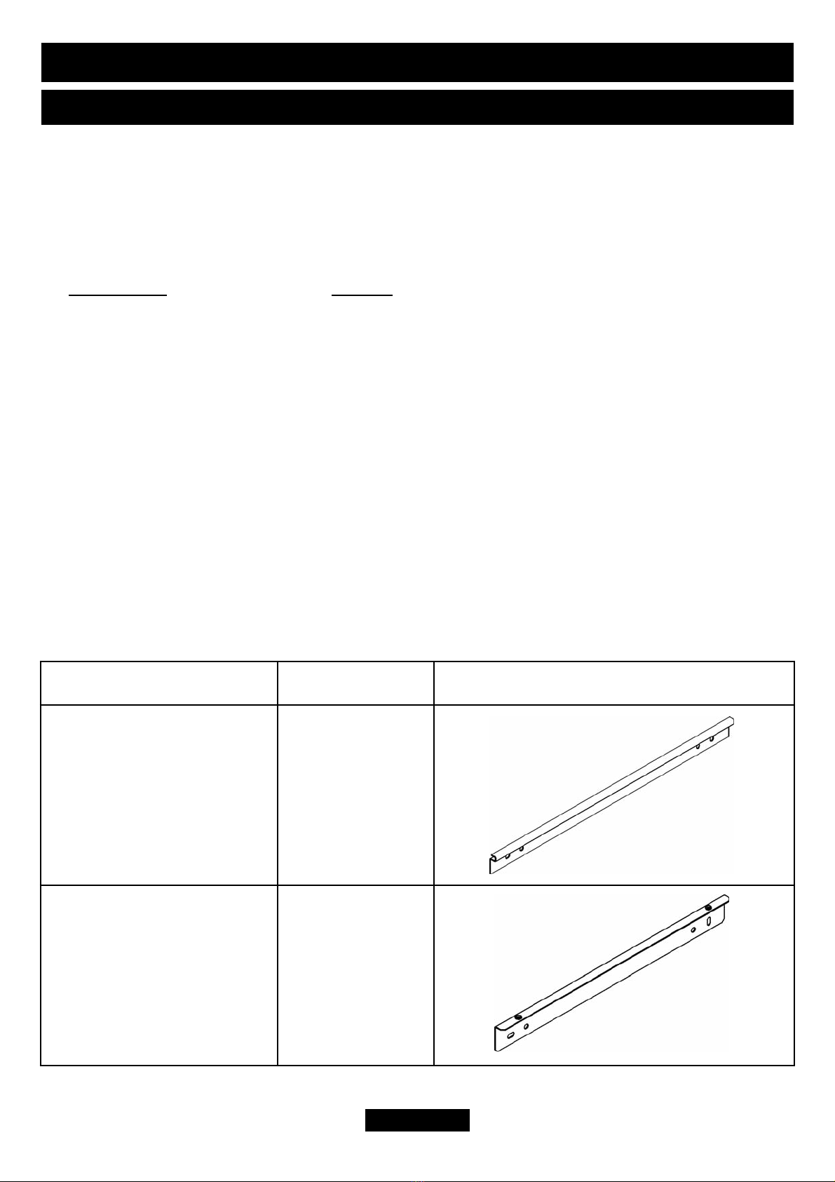
Fitting the lower wall bracket.
The lower wall bracket has four holes in
its rear and two threaded inserts in the
top. Locate the bracket centrally so that
the top is level with the base of the
builders opening. It is important that the
bracket is level, we therefore recommend
the use of a spirit level.
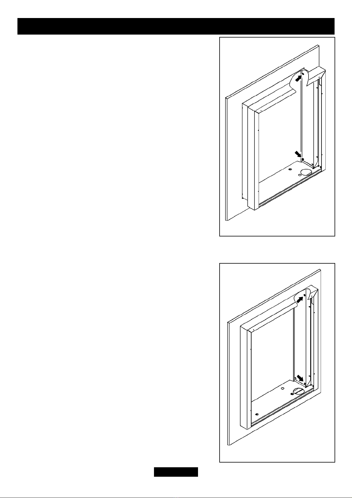
1. Mark the position of two of the four
fixing holes on the wall.
2. Remove the bracket from the wall and
drill the marked positions with a suitably
sized drill bit for the wall plugs supplied.
3. Insert two wall plugs.
4. Locate the bracket and secure using
two wood screws.
Page 7
© Baxi Heating U.K. Limited 2010.
Figure 1.