Valore VS-1204 Plus User manual

Version No.: V3.20160309
Easy Install Shower Panel
Installation and User Guide
VS
-1204 Plus
Français p.18
Español p. 35
ATTACH YOUR RECEIPT HERE
Serial Number Purchase Date
If you have questions relating to the use, warranty, return, claims and replacement,
please call: Phone: 877-551-0484 (Monday to Friday 8:30am-5:30pm PST)

• (H) 38.38" x (W) 3.94" x (D) 2.56"
• Hand shower hose: 59.05"
• Weight: Net: 8.7 lbs /Gross: 13 lbs
This product is tested and certified to
meet U.S. and international standards
cUPC-certified
• Single-piece curving panel design
• Full stainless steel casing
• Fingerprint resistant nanotechnology coating
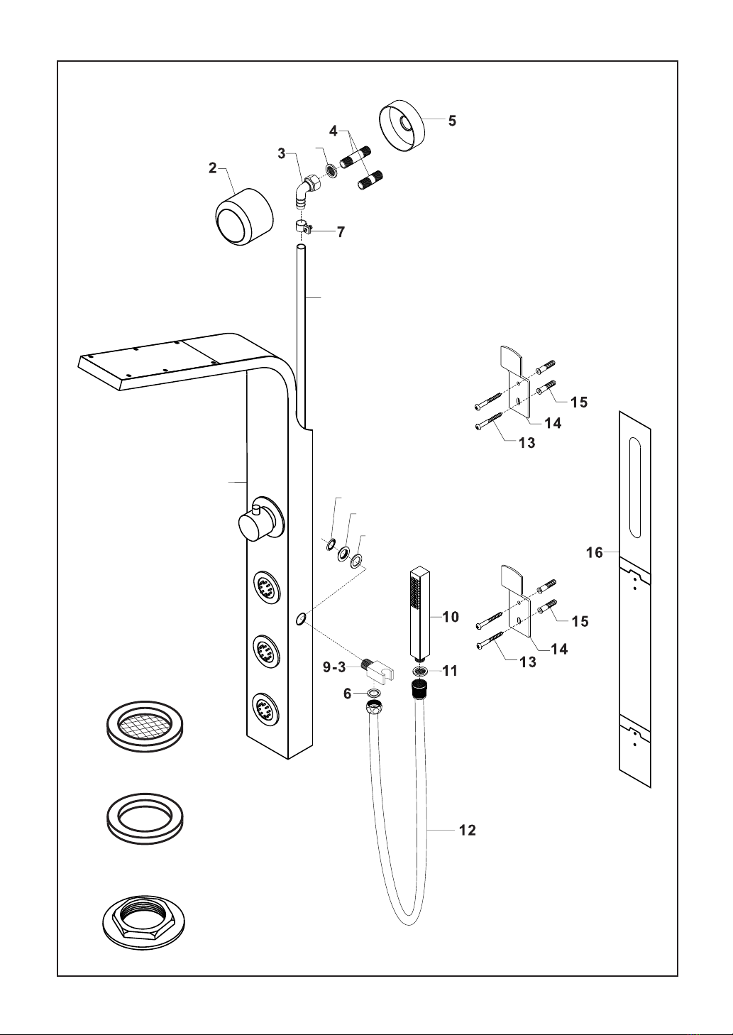
• 3 adjustable spray nozzle arrays
• 32-nozzle overhead "rainfall" shower array
• 6 spray settings with selector knob
• PVC hand shower in chrome outer finish
with cradle
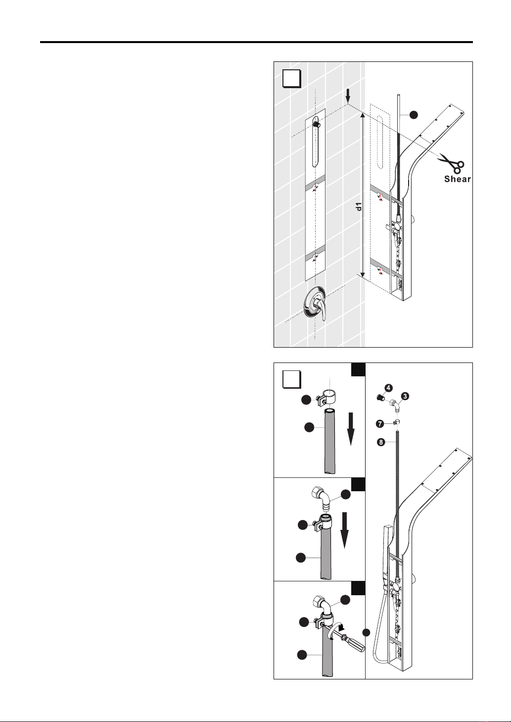
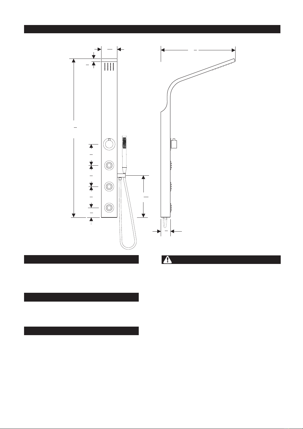
• Easy to install bracket system and connection
to existing shower head outlet
DIMENSIONS
DIMENSIONS
CODE COMPLIANCE
FEATURES
• Please read this Installation and User Guide before
installing and operating.
• Always take extra care when installing to prevent
injury. Please wear appropriate safety equipment.
• Do not allow children unsupervised use of the
shower panel.
• Do not use the shower panel if you are physically
impaired or under the influence of
alcohol or any substance which may prevent you
from properly operating the shower panel.
• Keep enough distance between yourself and the
shower panel.
• Do not allow sensitive parts of the body such as
eyes to come too close to the shower jets.
• Proper pressure balance needs to be maintained
between hot and cold water inputs to prevent
scalding or injury.
ATTENTION
- 2 -
15
316 "
4
1
18 8"
24"
3
58
1"
3"
3
38 8"
1
22"
58
1"
58
1"
1016 "
7

• Before and during installation, please read and familiarize yourself with all installation instructions for this product.
• Please keep all components, parts and accessories of this product away from small children and minors. During installation,
all screws,tools and small parts should be supervised so that they do not fall into the hands of children.
• Use caution at all times when installing this product. Please ensure that you are physically able to perform all parts of the
installation and that you have the correct tools and equipment needed.
• Before beginning,remove all wrappers and packinging materials including staples and packing straps.
• Please check to ensure that all components and parts are complete.
• The Filter Gasket (#11) must be installed to protect against incoming dirt by pipework. Incoming dirt can impair the function
and/or lead to damages on functional parts of the fixture. Manufacturer will not be held liable for resulting damages.
• The O Ring Gasket (# 6) must be installed to prevent water leakage. Manufacturer will not be responsible or liable from
any damage which results directly or indirectly from failure to installation of the O Ring Gasket.
IMPORTANT NOTE
RECOMMENDED TOOLS FOR INSTALLATION
-
PH +
2.5 mm
Drill Bit 6mm
Electric Drill Wrenches
24 mm /30mm
Vice Pencil / Shear
Screwdriver Hexagon-wrench Level Sealing Tape
Pliers
NO.
1
2
3
4
5
6
7
8
9
10
11
12
13
14
15
16
Description
Shower Panel Casing
Shower Head Outlet Connector Cover
Elbow Connector
Brass extender joint (1 5/8"& 2 5/8"x ½")
Base Plate Cover with Tape (for Shower Head Outlet Connector Cover)
O Ring Gasket
Ring Clamp
Main PVC Supply Line (43"/110cm)
Handshower Cradle Assembly
PVC Handshower
Filter Gasket
Handshower Hose
Screws
Positioning and Support Brackets
Screw Anchor
Installation Template Guide
Qty
1 Set
1 Pc
1 Pc
2 Pcs
1 Pc
2 Pcs
1 Pc
1 Pc
1 Set
1 Pc
2 Pcs
1 set
4 Pcs
2 Pcs
4 Pcs
1 pc
PARTS LIST
- 3 -
Hammer

- 4 -
11
6
9-1
8
1
9-2
9-1
6
11

ASSEMBLY
b
cd
1
9-3
9-3
9-1
6
9-1
9-2
9-3
a
12
11
10
6
9-3
9-3
- 5 -

• Before Installation, insure there is sufficient
clearance to accommodate the shower panel.
A minimum of 28” is required between the
shower outlet and top of your existing valve.
Maximum clearance required 42”.
Ensure that the water line to the overhead
shower pipe is completely shut off prior to
performing any work.
• Remove the existing shower head and show
head arm.
• Connect the Brass Extender Joint (Part 4)
we provided to the showerhead pipe outlet.
Use waterproof plumbing tape on the thread
prior to securing the extender to prevent leaks.
(Note: There are 2 sizes of the brass extender.
Choose the appropriate size).
INSTALLATION INSTRUCTIONS
½" diameter is needed to
accommodate the shower panel's
Brass Extender Joint (Part 4)
- 6 -
MIN 28 Inch

How to use Template:
• Connect the brass extender joint provided.
• Place the installation template in the desired position over the wall with the brass extender joint positioned
going through the cutout on the template. It is recommended that the tallest user in the house be the determining
factor of the desired position. 10” of clearance above the tallest user is recommended.
• Once the template is in the desired position, secure the template by using tape or a temporary adhesive to hold
it in place.
• The template is the exact size of the shower panel. The bottom of the template should be above your existing
shower valve. Recommended that there is a ½” clearance above the valve.
• If the template does not fit with the clearance provided, you can mount the panel off center and to the side.
Installation Template Guide
PVC cover is not
required if the water
outlet is below 33.38"
Valve goes below this
template. Bottom of
panel.
• An installation template guide
is included with your shower
panel as a convenient method
of determining the correct
position of the shower panel.
MIN ½ Inch
4
4
Installation position will
vary depending on
users height. Depending
on users height, it is
recommended to have
10” of clearance above
your head.
A
C
B
Attention:
INSTALLATION INSTRUCTIONS
- 7 -
Recommended
10"

This section will guide you on measuring the
required length of the Main PVC Supply Line
(Part 8) relative to the final position of the
Template Guide
Steps:
• Measure the distance between the bottom of
the template to the closest approximate hole
position on the top of the template which
corresponds to where the shower outlet pipe
is. Refer to this distance as "d1".
• Add 1 inch to your "d1" measurement.
• Using the length of "d1" as a guide, measure
this length on the Main PVC Supply Line Hose
(Part 8) and shear the excess length from the
hose.
Draw a level horizontal line based on
the lower-edge of the selected hole
Connecting the Supply Line Elbow to the main
PVC Supply Line:
1. Insert the Ring Clamp (Part 7) onto the end
of PVC Supply Line (Part 8).
2. Fully insert the grooved end of the Elbow
Connector (Part 3) into the PVC Supply
Line (Part 8).
3. With a Phillips head screwdriver, tighten the
bolt and nut on the Hose Clamp (Part 7) until
the PVC Supply Line is secured to Elbow
Connector (Part 3).
4. The Elbow Connector (Part 3) will be secured
to the Brass Extender Joint (Part 4) in a later
step.
8
7
6
8
7
3
8
7
3
PH +
1
2
3
5
INSTALLATION INSTRUCTIONS
- 8 -
8

• Use the drill with correct indicated sized drill
bit to drill each of the 4 holes as marked in
step 6. Do not drill too deep a hole - only
enough depth to fully enclose the anchor
screws. Note: Please double check to ensure
there is no existing water pipes or obstruction
behind area you are drilling. If there is an
obstruction, you will need to reposition the
template guide to avoid it.
• After holes have been drilled, insert the
provided Anchor Screws (Part 15).
• To ensure the template (and your shower panel)
will be in a completely straight and level position,
use a level tool against the side of the template
guide to make fine adjustments to the template
guide's position until fully level.
• Once fully level, this will be the final position of
the template guide.
• Take a pencil/marker and mark the positions of
the anchor screws (Part 15) for which 4 holes
will need to be drilled.
9
7
8
15 x4PCS
INSTALLATION INSTRUCTIONS
- 9 -

• After anchor screws have been installed, affix
the Positioning & Support Brackets (Part 14)
using supplied Screws (Part 13).
For the Positioning & Mounting Brackets
(Part 14), please make sure that they are
installed with protruding portion facing
upward as shown in the drawing.
14
11
10
INSTALLATION INSTRUCTIONS
- 10 -
14 x2PCS
13 x4PCS
PH +

• After all connections have been completed
inside the shower panel, it is ready to be
hung on the shower wall for installation.
• Raise the shower panel and bringing it to the
surface of the shower wall and gently lower
it until the bracket support struts on the back
of the shower panel meet the support brackets
( Part 14) installed in Step 10. Please ensure the
brackets (Part 14) are centered on the groove
on the support struts.
• Once a snug and secure fit is achieved and all
parts of the PVC Supply Line are secured to the
back of the shower panel, silicone sealant can
be applied to seal the gap between the shower
panel casing and the shower wall to hold it in
place and prevent water from entering behind
the panel.
1. Peel off the paper backing to the adhesive ring
for the Base Plate cover (Part 5).
2. Place the adhesive side to the wall and apply
pressure to secure the Base Plate Cover
(Part 5). (Note: Remove all residues to insure
the cover will bond properly)
3. Add a Filter Gasket (Part 11) into Elbow Joint
(Part 3) first.Then attach the Elbow Joint (Part 3)
to the Brass Extender Joint (Part 4), turn clock
wise to tighten.
4. Place the Showerhead Cover (Part 2) to
conceal plumbing fixture.
NOTE: If the water outlet is below 33.38” on the template, the PVC cover is not required.
INSTALLATION INSTRUCTIONS
- 11 -
11
14
14
13

b
* For Safety, it is highly recommended that you familiarize yourself with all applicable local plumbing codes before
installing this product.
125psi
50~80psi
45psi ,125ps
93.2~107.6 F
<2.0gpm
Technical Data
Maximum operating pressure:
Recommended pressure:
Test pressure:
Recommended hot water temperature:
Flow rate @ 80 psi:
How to use Diverter
NOTE: Please turn on the Faucet first.
• Hand Shower Position
When the position knob is placed in”b”.
• Spray Position
When the position knob is placed in”c” .
When the position knob is placed in ”a”.
• Shower Head Position
When the position knob is placed in between each
dot mark, this will result in a sharing of water output
between 2 operating modes .This can be used if
combination of 2 modes is desired however the
water output will be reduced due to sharing of water
flowing through the system between those 2
operating modes.
Two modes simultaneously•
When the position knob is placed ”d”, the
handshower and the top hydro jets will work
simultaneously.
- 12 -
a
b
c
d

Diverter Valve Structure
Diverter valve
How to Remove the Diverter Valve
5
4
3
1
2
• Remove the handle to open the set screw access hole.
1
• Loosen the set screw (#1) from the valve stem and pull
the knob (#2) straight out.
2
(2.5 mm)
3
2
1
1
• Loosen and remove the gland nut (#4). • Remove the Diverter valve (#5) by pulling it straight out.
4
4
3
5
Diverter valve
4
- 13 -

2
5
Diverter valve
1
How to Install the Diverter Valve
• Place the Diverter valve (#5) into the valve body. Note
the one pillar on the bottom of the Diverter valve (#5)
must be aligned with the hole in the rear of the body.
• Tighten the gland nut (#4). Take precaution to avoid
scratching the trim plate. Do not force the nut too
tightly.
4
4
3
Adjust the knob with right position
Shower Head Mode
2
• Replace the knob (#2) on the valve stem.
• Before securing the knob, turn on the water to know
which way the handle is to be pointed.
5
4
(2.5 mm)
3
2
1
1
• Tighten the handle (#3) and nish the install.• Once the correct position of the knob has been
determined, place the knob on the valve stem and
tighten the set screw (#1). Do not overtighten.
2
- 14 -

• Loosen the nut securing the PVC Flexible hose to (#8)
the brass valve body.
• Disconnect the PVC hose from the valve body and
remove the Filter Gasket (#11).
• Using needle nose pliers, grip the edge of the check
valve and pull straight out..
2
3
Check Valve
1
• Place the new check valve into the valve body.
Observe the direction of the valve is correct.
2
4
Check Valve
2
2
11
2
• Ensure the check valve is ush with the top of the valve
body inlet.
5
Level
• Place the lter gasket (#11) back in place and secure the
PVC hose (#8) to the valve body to complete the install.
2
6
How to Replace the Check Valve
8
- 15 -
11
8

Problem Possible Causes Remedy
Limited water flow
- Check water pressure (If a pump has
been installed check to see if the
pump is working)
- Clean Filter Gasket between shower
and hose
Troubleshooting
Cleaning Recommendations
Cleaning Procedures
• Required cleaning your faucets and shower products,
regular cleaning will prevent scale buildup and water
spotting.
• Follow the label instructions. Do not allow any cleaner
to remain on the product for longer than necessary.
• When using spray cleaners, Please spray first to a
sponge or cloth, Don’t spray directly to the product.
• Please use clean water to rinse to remove residual
cleaners and dirt.
Important
• Soap and shampoo residue can also cause damage to
the product. Rinse with clean water after use.
• If the surface is already damaged, harsh cleaning
materials will cause further damage.
Crossflow, hot water being forced
into cold water pipe, or vice versa,
when mixer is closed
- Check valves dirty or leaking - Clean check valves, exchange if
necessary
- Dirt or sedimentation on valve seat,
shut-off unit damaged
- Clean or exchange shut-off unit
Shower drips continuously
Modern faucets and shower products utilize a combination
of materials to comply with the needs of the market with
regard to design and functionality.
To avoid damage, it is necessary to use some caution
when cleaning. Damage caused by improper treatment
is not covered under the warranty.
Cleaning Materials for Faucets and Showers
• To remove lime scale, use only products made
specifically for that purpose. Always follow the
manufacturer’s instructions when using.
• Do not use cleaners that contain hydrochloric,
formic, acetic, or phosphoric acids, as these will
cause considerable damage to finishes and to
plastic components.
• Never mix cleaning materials.
• Never use cleaners containing abrasives. Do not
use abrasive cleaning cloths, pads, or sponges.
- Supply pressure inadequate
- Filters Gasket are dirty
- 16 -

Valore (“Seller”) and the person or entity that acquires these
goods from Seller (“Purchaser”) hereby fully agrees to the
following terms and conditions of the sale: Shipping fees are
the responsibility of the Purchaser whether freight prepaid
or freight collect. Seller assumes no responsibility for the
goods sold to the Purchaser once the goods have left the
Seller’s premises, including but not limited to, late delivery
by the moving carrier, or for events caused by any difficulty
carrier incurs in attempting to fit the goods into the
Purchaser’s place of business or residence due to size of
the goods or otherwise Purchaser assumes all responsibility
for delivery, payment of freight, access, measurement,
installation, hook-up, wiring, moving and storage of the
goods. The transportation of all goods is subject to the terms
and conditions which the moving carrier imposes on
Purchaser including, but not limited to, additional charges
imposed per flight of stairs, and/or additional charges
resulting from the carrier’s inability to safely and/or
adequately use the building elevator to lift the goods to an
upper level. Any claim for damages incurred during the
shipment by the carrier of the goods are insured and
handled directly with the carrier. Any damages due to
manufacture defects will be handled directly with Valore,
subject to the limited warranty.
All sales are final, and unless authorized in writing by the
Seller, Purchaser may not return the goods, under any
circumstance. If Purchaser refuses to accept the goods,
under any circumstance, the Purchaser is liable for the
return and cost of freight both ways, and if seller does take
the goods, there may be a restocking fee that of 20% of the
purchase price of the goods in addition to the freight.
Purchaser must notify Seller of non-conforming goods
within seven (7) days of delivery, after which time all goods
are deemed accepted. If an order has been placed and
production started, cancellation cost of your order will be
20% or the purchase price.
The limited warranty does not cover damage due to
such things as accident, misuse, abuse, mishandling,
neglect, acts of God, fires, earthquakes, floods, high
winds, government, war, riot or labor issues defined
as strikes, lockouts, delay of carrier, unauthorized
repair, or any other beyond the control of the Seller
whether similar or dissimilar to the foregoing. Seller is
not responsible for any damages caused by the
Purchaser misusing, mishandling or abusing the
intended the use of the goods. Limited warranty
applies only inside the Continental U.S. or Canada
(Alaska, Puerto Rico Hawaii, Yukon, Northwest
Territories, and Nunavut not included). The limited
warranty is not transferrable between the US and
Canada.
The limited warranty is only valid with the provision of
proof-of-purchase from an authorized retailer of Valore
branded products.
Seller is not responsible for labor expenses that are
incurred due to service or installation charges.
Seller is not responsible for incidental or consequential
damages and there are no warranties, expressed or
implied, which extend beyond the limited warranty
described above. The implied warranties of
merchantability and of fitness for a particular purpose
are hereby expressly disclaimed. Some states do not
allow the exclusion of incidental or consequential
damages, or a waiver of the implied warranties of
fitness and/or merchantability, so the above limitations
may not apply to you. This warranty gives you specific
legal rights and you may have other rights, which vary
from state to state.
LIMITED WARRANTY
One (1) year guaranteed from manufacture defects
Two (2) years limited parts warranty covering the
thermostatic valve, pressure balance valve, mixing valve,
and diverter valve.
Recycling: Most of the materials used to manufacture this
shower fixture are recyclable. Please dispose of those
materials properly in accordance to your local state laws.
Improper disposing of this shower fixture can be harmful to
the environment.
LENGTH OF WARRANTY
If you have questions relating to the use, warranty,
return, claims and replacement, please call:
Phone: 877-551-0484
(Monday to Friday 8:30am-5:30pm PST)
Email us at [email protected] (24 hour)
For more information, you can visit us at:
www.valoreusa.com
- 17 -

No de version.: V3.20160309
Panneau de douche facile à installer
Guide d'installation et d'utilisation
VS-
1204 Plus
JOINDRE VOTRE REÇU ICI
Numéro de série Date d’achat
Si vous avez des questions concernant l’utilisation, la garantie, le retour, les
réclamations et le remplacement, veuillez appeler au numéro suivant :
Téléphone : 877-551-0484 (lundi au vendredi, de 8 h 30 à 17 h 30 HNP)
- 18 -

DIMENSIONES
- 19 -
DIMENSIONES
• (H)38,38 po x (L)3,94 po x (P) 2,56 po
• Tuyau de douche téléphone : 59,05 po
• Poids : Net - 8.7 lb/Brut - 13 lb
CARACTÉRISTIQUES
CONFORMITÉ AUX CODES
Ce produit a été testé et il respecte les normes
américaines et internationales cUPC.
• Panneau de douche monobloc au design courbé
• Boîtier en acier inoxydable à 100 %
• Revêtement nanotechnologique résistant aux
taches de doigts
• Trois grands gicleurs ajustables
• Pomme de douche à 32 trous pour une douche de
type pluie
• Commande permettant de choisir parmi six types
de jet d'eau
• Douche téléphone en PVC avec fini chromé et
support
• Support et raccordement au tuyau
d'approvisionnement existant faciles à installer
• Veuillez lire ce guide d'installation et d'utilisation
avant d'utiliser l'appareil.
• Faites toujours preuve de prudence lors de
l'installation pour éviter de vous blesser. Veuillez
utiliser de l'équipement de sécurité approprié.
• Ne laissez pas d'enfants utiliser le panneau de
douche sans surveillance.
• N'utilisez pas le panneau de douche si vous avez
une déficience physique ou si vous êtes sous
l'effet de l'alcool ou de toute substance pouvant
vous empêcher de faire fonctionner adéquatement
le panneau de douche.
• Maintenez une distance suffisante entre vous et le
panneau de douche.
• Ne permettez pas que des parties sensibles de
votre corps, comme vos yeux, soient trop près des
jets d'eau du panneau de douche.
• Un bon équilibre doit être maintenu entre l'eau
chaude et l'eau froide pour éviter tout risque
d'ébouillantage ou de blessure.
ATTENTION
15
316 "
4
1
18 8"
24"
3
58
1"
3"
3
38 8"
1
22"
58
1"
58
1"
1016 "
7

-
PH +
NO.
1
2
3
4
6
7
8
9
10
11
12
13
14
15
16
Q É
1 ens.
1 pièce
1 pièce
2 pièces
2 pièces
1 pièce
1 pièce
1 ens.
1 pièce
2 pièces
1 ens.
4 pièces
2 pièces
4 pièces
1 pièce
CONSIGNES D’INSTALLATION IMPORTANTES
• Avant et pendant l'installation, veuillez lire et prendre note de toutes les instructions d'installation de ce produit.
• Veuillez garder tous les éléments, pièces et accessoires de ce produit loin de la portée de jeunes enfants et de
mineurs. Pendant l'installation, tous les outils, vis et petites pièces doivent être sous surveillance pour éviter
qu'ils ne tombent entre les mains d'enfants.
• Faites preuve de prudence en tout temps lors de l'installation de ce produit. Veuillez vous assurer d'être
physiquement capable de procéder à toutes les étapes de l'installation et d'avoir en votre possession tous les
outils nécessaires.
• Avant de commencer, enlevez tout le matériel d'emballage, y compris les agrafes et les sangles.
• Veuillez vous assurer que tous les éléments et toutes les pièces sont inclus.
• Le joint d'étanchéité du filtre (pièce 11) doit être installé pour empêcher que de la saleté s'infiltre dans le conduit.
La saleté peut nuire au fonctionnement du panneau ou endommager des pièces fonctionnelles de l'appareil de
plomberie. Le fabricant ne pourra être tenu responsable des dommages survenant à la suite du non-respect de
cette consigne.
• La bague ronde d'étanchéité (pièce 6) doit être installée pour empêcher toute fuite. Le fabricant ne pourra être
tenu responsable des dommages causés, directement ou indirectement, lorsque la bague ronde d'étanchéité
n'est pas installée.
OUILS RECOMMANDÉS POUR I’INSTALLATION
Marteau
Mèche de (15/64 po)
Perceuse électrique Clés Pince
Tournevis Clés Niveau Ruban d'étanchéité
(3/32 po)
22mm (15/16 po)
Pince à becs pointus
LISTA DE LAS PIEZAS
DESCRIPTION
Boîtier du panneau de douche
Couvercle du tuyau de sortie de la pomme de douche
Connecteur en coude
Joint d'extension en laiton (1-5/8 po et 2-5/8 po x ½ po)
T
Bague ronde d'étanchéité
Bride de serrage
Tuyau d'alimentation principal en PVC (43 po/110 cm)
Assemblage du support de la douche téléphone
Douche téléphone en PVC avec fini chromé
Joint d'étanchéité du filtre
Tuyau de la douche téléphone
Vis
Supports de soutien et de positionnement
Vis d'ancrage
Gabarit d'installation
5Couvercle de la plaque de base avec ruban (pour le connecteur du tuyau
de sortie de la pomme de douche) 1 pièce
- 20 -
Crayon / Ciseaux
Table of contents
Languages:
Other Valore Bathroom Fixture manuals
Popular Bathroom Fixture manuals by other brands

Alcad
Alcad LLC-120 Assembly instructions

WERKAPRO
WERKAPRO 10868 instruction manual

Bristan
Bristan VAL2 BIB C CD Installation instructions & user guide

Axor
Axor Starck 10715 1 Series Installation/User Instructions/Warranty

daewon
daewon DIB-N800 Series user manual

Graff
Graff TEP92 installation instructions