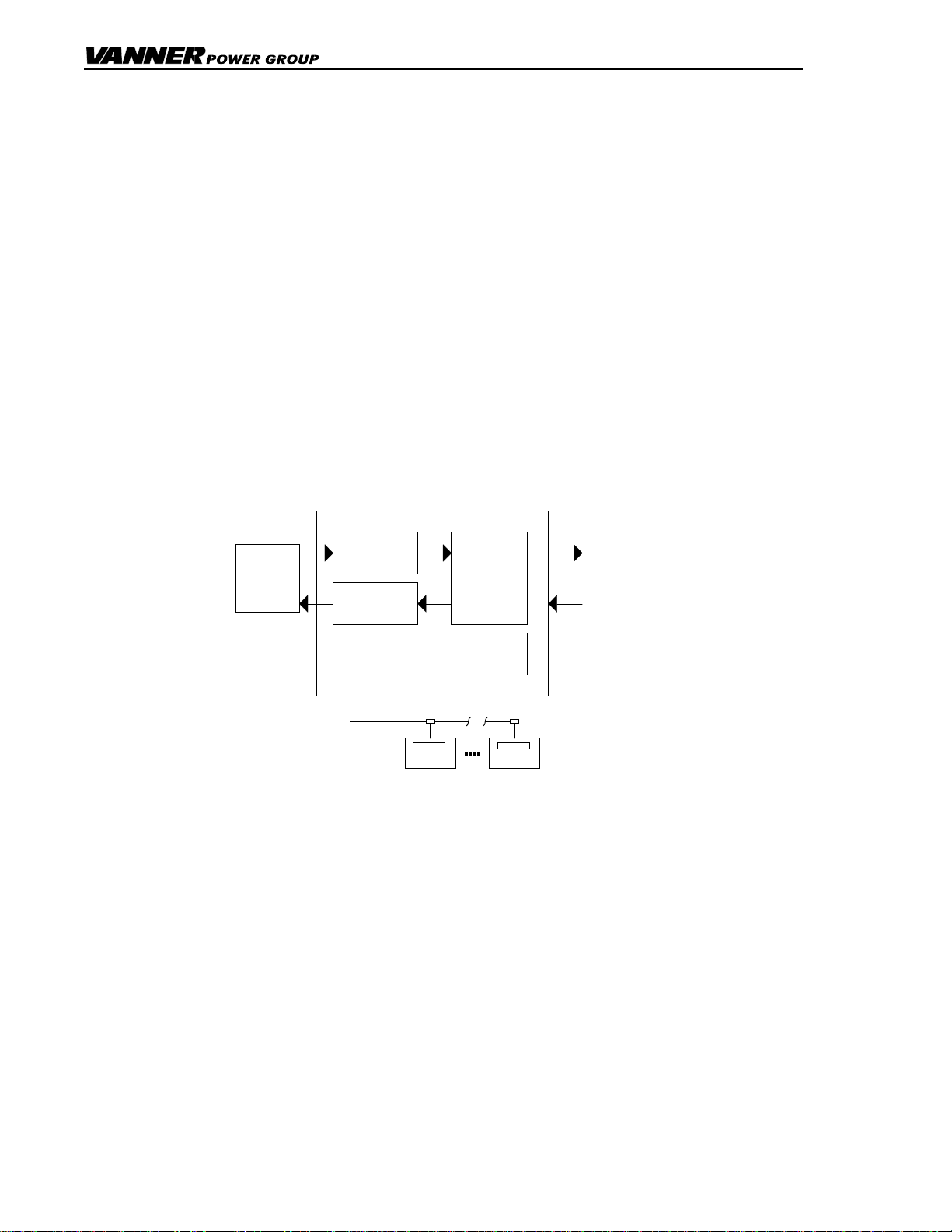
Description of Operation
TruSine 4.5 kW Inverter Page 9 Owner’s Manual
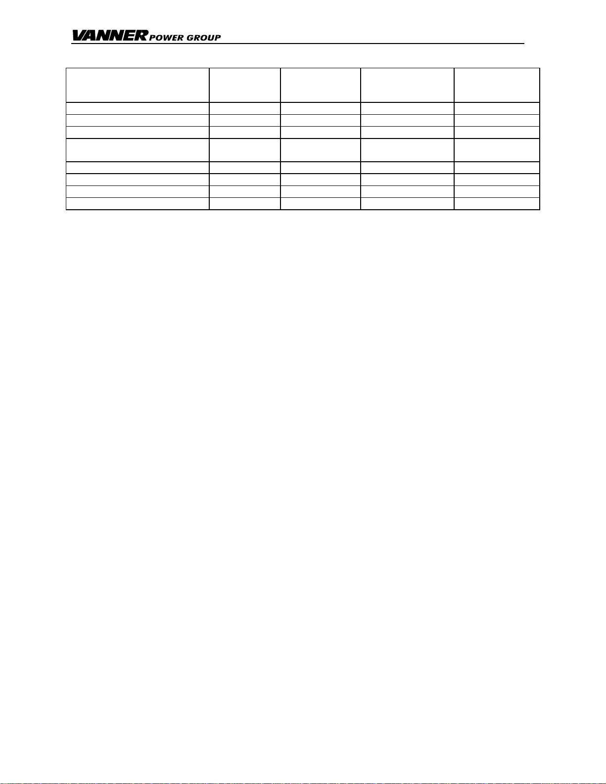
Battery Charger Factory Setpoints (Factory Setpoints are for wet batteries, 4 size 8-D minimum.)
All Charging Setpoints are
Password Protected in the
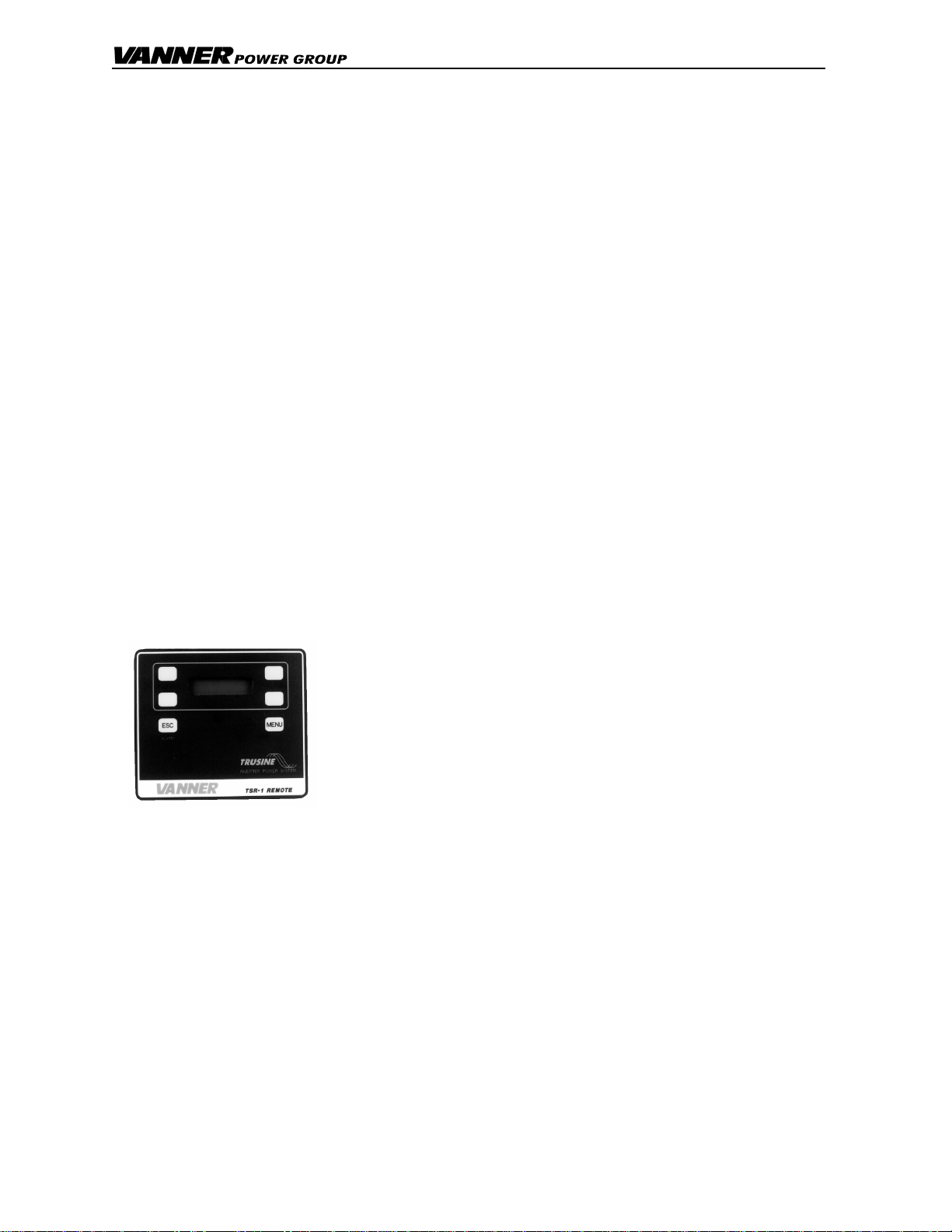
TSR-2 Remote Control
Guideline Setpoint
Range Factory Setpoint
(for Wet Battery) Typical setpoint
for
Gel Battery
Bulk Charge Volts 26.0 - 32.0 28.4 VDC 28.1 VDC
Bulk Charge Amps 20% C Rate 0 - 100 100 Amps 20% C Rate
Absorption Charge Volts 28.0 - 34.0 30.0 VDC 28.2 VDC
Absorption Charge Amps 5% C Rate
minimum 10 - 50 50 Amps 5% C Rate
minimum
Absorption Maximum Time 10 - 255 10 Minutes 10 minutes
Float Charge Volts 26.0 - 30.0 26.4 VDC 27.2 VDC
Equalize Volts Wet only 26.0 - 34.0 31.0 VDC Not used
Equalize Maximum Time Wet only 5 - 30 15 Minutes Not used
Battery ‘C Rate’ is equal to battery Amp Hour capacity.
Automatic Power Management (APM)
A key feature of the battery charger operation is Automatic Power Management (APM). This feature monitors
the Aux AC input amps and will reduce the battery charger output as necessary to keep the Aux AC input amps
under the APM setpoint. The APM circuit will not limit power to the passthrough AC loads. If the passthrough
AC loads exceed the APM setpoint the battery charger output will be reduced to zero.
Adjust the “APM Limit” setpoint to match the circuit breaker at the Aux AC source. This will reduce the chance
of tripping the source’s circuit breaker due to battery charging.
On model TSC24-4500D (240VAC) the APM feature monitors L1 and L2. APM decisions are based on the
heavier loaded line.
Example: With the APM Limit on a TSR24-4500D set at 15 amps, L1 loaded to 15 amps and L2 has no
load, then the APM will allow no power to go to charging. If the load on L1 is reduced to 10 amps then
the charger will be allowed to use 5 amps.
2.3 Automatic Transfer Switch with Solar Mode
The Automatic Transfer Switch consists of electro-mechanical relays controlled by circuits which monitor Aux
AC input voltage, Aux AC Input frequency and battery voltage.
In the normal mode of operation, Solar Mode OFF, the Automatic Transfer Switch will automatically accept ‘in-
tolerance’ Aux AC input power whenever it is available within tolerance for the ‘AC Line Stabilization’ time delay.
The Aux AC input power will be used to operate the battery charger and to passthrough to operate AC loads.
Upon loss of ‘in-tolerance’ Aux AC input power, the transfer switch will automatically transfer the AC loads back
to inverter power. Transfer time is approximately 40 milliseconds (0.040 seconds). The 0.040 second transfer
time allows all but the most sensitive loads to transfer from inverter power to shore power and back without
interruption.
The Transfer Switch will function properly as long as the System ON/OFF switch is ON even while the Inverter
is disabled, while the Battery Charger is disabled or while the batteries are disconnected from the system.
The Transfer Switch switches both hot and neutral. For safety purposes the inverter output neutral is connected
to the inverter chassis ground only when the system is in inverter mode. This is a requirement of the National
Electric Code for all systems of this type that neutral should be connected to ground only at the source of AC
power, which is the inverter when in inverter mode. When Aux AC input (shore power, or generator) is
available, the Transfer Switch system breaks the connection between neutral and inverter chassis ground. The
neutral-to-ground connection for passthrough power is then expected to be provided by the Aux AC input
source. This transfer scheme presents no problems for a properly installed system. The installer should verify
that all AC circuits connected to the inverter AC output are an insulated neutral type as required by the National
Electrical Code (NEC) article 551.
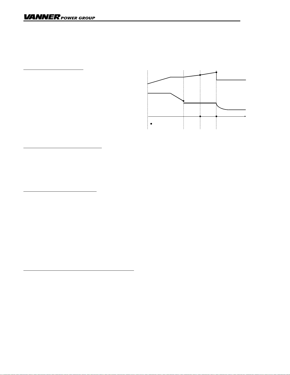
Solar Mode
Turn Solar Mode ON in applications where it is preferred to operate on battery power while ‘in tolerance’ Aux
AC input (shore power) is avaliable. With Solar Mode ON, the inverter will operate on battery power while Aux
AC input is available until battery voltage falls below the Low Battery Warning setpoint. Then the system will