Vanner VSC12 User manual

Owner's Manual
VCS12/24 Battery Charger Page 1
VSC12/24
BATTERY CHARGER
OWNER’S MANUAL
D913335-A

Owner's Manual
VCS12/24 Battery Charger Page 2
Notes

Owner's Manual
VCS12/24 Battery Charger Page 3
Contents
page
1) Description 3
2) Specification 3
3) Installation 4
4) Connections 6
5) Charging method 7
6) Thermal Ratings 8
7) Internal switch settings 8
8) Internal fuses 10
9) Standards 10

Owner's Manual
VCS12/24 Battery Charger Page 4
1) Description
•The VSC12/24 is a 1.2kW, 12/24V battery charger intended for vehicle
mounted applications.
•The output voltage is 12 or 24V nominal, set by internal switches.
•No adjustments necessary, settings held in EEPROM.
•The input voltage is 120Vac at a maximum of 15A current.
•Fully automatic operation with three-stage battery charging.
•Over current protection of ac input & dc output to protect both the charger &
the batteries.
•Cooling is by temperature controlled fans to reduce noise & increase fan life.
•Automatic reduction of output current occurs at high temperatures (above
122°F [50°C]) and at low mains (to maintain 15A maximum input).
•A remote charger operating indicator signal is provided.
•3 LEDs show the charger status.
•Reverse voltage protection is provided by an internal fuse.
•Durable steel enclosure.
2) Specification
Input 15A max. at 88 – 132Vac, 54 – 66Hz
Power factor >0.9 at 120Vac, 75 – 100% load
Output 42A at 24 or 12Vdc nominal (supplied set to 24V)
DC current draw 30mA max. (with no ac voltage applied)
Bulk voltage 28.6 or 14.3Vdc nominal (±0.1V)
Float voltage 26.6 or 13.3Vdc nominal (±0.1V)
Ambient temperature -40 to +140°F (-40 to +60°C)
Signal Switches anything connected to this terminal to
–dc output (vehicle ground) when charger
operating. Maximum current 5A. Not protected.
Cooling Forced air, 2 x 23CFM, 12V 250mA fans with flow
from fan end to connector end
Chassis Steel with durable painted finish
Weight 12.8lbs (5.8kg)
Dimensions 9.61” W x 2.76” H x 14.49” D (247.4 x 70.0 x
368.0mm)

Owner's Manual
VCS12/24 Battery Charger Page 5
3) Installation
3.1) Location
•The charger should be located close to the battery (but not in the same
compartment) for optimum performance (within 3ft [900mm]).
•The charger should be protected from weather. Install the charger in
compartments that provide protection from direct water spray, dirt or toxic
vapour.
•The mounting compartment should be well ventilated & allow adequate air
circulation. (2” [50mm] clearance at both the fan & connection ends is
recommended.)
•Do not store flammable items near the charger.
3.2) Mounting
The charger has four ¼-20 UNC threaded inserts in its base for mounting, as
shown below:
Maximum screw penetration must be less than 2.6”
10.75"
BOTTOM VIEW
CONNECTION END 1"
8.75"
0.5"
4 x ¼-20 UNC threaded inserts

Owner's Manual
VCS12/24 Battery Charger Page 6
There are also 4 x 10-32 UNF threaded inserts in the top which may be used to
mount another item of weight not exceeding 12.8lbs (5.8kg). Fixing positions as
shown below:
Maximum screw penetration must be less than 0.5”
8"
3"
TOP VIEW
CONNECTION END
8"
0.87"
4 x 10-32 UNF threaded inserts

Owner's Manual
VCS12/24 Battery Charger Page 7
4) Connections
Connections are made by removing the 10 metric M4 cover fixing screws (4 on
top & 3 down each side), removing the cover, & connecting to the terminals on
the internal circuit board as shown below:
Input. The input cable must be a 3 core utility power cable with outer insulation,
the inner core insulation color coded as follows & rated at 120V 15A:
Connection Color
Live, marked L on diagram black
Neutral, marked N on diagram white
Safety ground (earth) marked E on diagram green
WARNING: Do not operate without a safety ground connection!
Output. The output cables must be rated at 45A 32V & color coded as follows:
Connection Color
Positive, marked + on diagram, to battery + red
Negative, marked - on diagram, to battery –
(vehicle ground) black
Signal. If utilised, a cable rated for 5A 32V should be used.
Route all cables away from hot or sharp surfaces or components.
N
E L
3 x metric M4 screws
2 x metric M6 studs
CONNECTOR END OF INTERNAL CIRCUIT BOARD
Utility power input 120Vac 60Hz
+
-
24V (or 12V) DC output
signal
¼" faston

Owner's Manual
VCS12/24 Battery Charger
Page 8
The cables must be passed through the appropriate cover holes & secured in
strain relief bushes as shown below:
5) Charging method
The charging status is indicated by two of three LEDs as shown below:
The charger will automatically switch between a float charge output voltage & a
bulk charge output voltage depending on load conditions.
At start up, the charger is in float mode & the green LED will be illuminated. If the
load current exceeds ~75% of full load for more than 10 seconds, then the
charger will switch to bulk charge mode, increasing the output voltage &
illuminating the yellow LED.
+
-
CONNECTION END VIEW
Holes for 3 x ¾" + 1 x ½" strain relief bushes
Remote
indication AC inputDC output
FAN END VIEW
yellow:
bulk,
absorption
green:
float
red;
over temperature

Owner's Manual
VCS12/24 Battery Charger
Page 9
When the battery is charged to the point where the charging current falls below
~75%, a 20 minute timer is started allowing the battery to be fully charged in
absorption mode. After 20 minutes, the charger returns to float charge mode,
reducing the output voltage & illuminating the green LED.
If at any time the load current subsequently exceeds ~75%, the charger switches
back to bulk mode, or if in the 20 minute absorption period, disables the timer,
restarting it when the current falls below ~75%.
Should the current fall below ~5% of full load, the charger will immediately switch
to float mode.
If the charger is connected to a battery, but not connected to utility power, or the
utility power has failed or dropped below 88Vac, the green LED blinks to warn of
power failure.
6) Thermal ratings
The charger will provide 42A in ambient temperatures between -40 to +122°F (-
40 to +50°C). At less than 32°F (0°C), full specified performance is not
guaranteed until after a warm up period.
Above 122°F (50°C), the output current is reduced linearly towards 33A at 140°F
(60°C). At ~140°F (60°C) a thermal cut out operates which reduces the output to
~4A & illuminates the red LED. When the internal heatsink temperature falls by
~36°F (20°C), the charger switches back to full power. This cycle continues
indefinitely until the ambient temperature falls below 140°F (60°C).
Operational exposure to temperatures above 150°F (65°C) can activate a backup
thermal trip which shuts down the output completely. No LEDs are illuminated in
this condition, however the charger will switch itself back on when the
temperature reduces.
This thermal trip can also operate if either or both fans fail, or if the airflow into
the fans or out of the opposite end of the charger, is blocked.
7) Internal switch settings
The charger has an internal, 4-pole, circuit board mounted, miniature switch to
change the output from 24V nominal to 12V nominal & to disable bulk mode,
allowing the charger to be used as a power supply, rather than a charger.
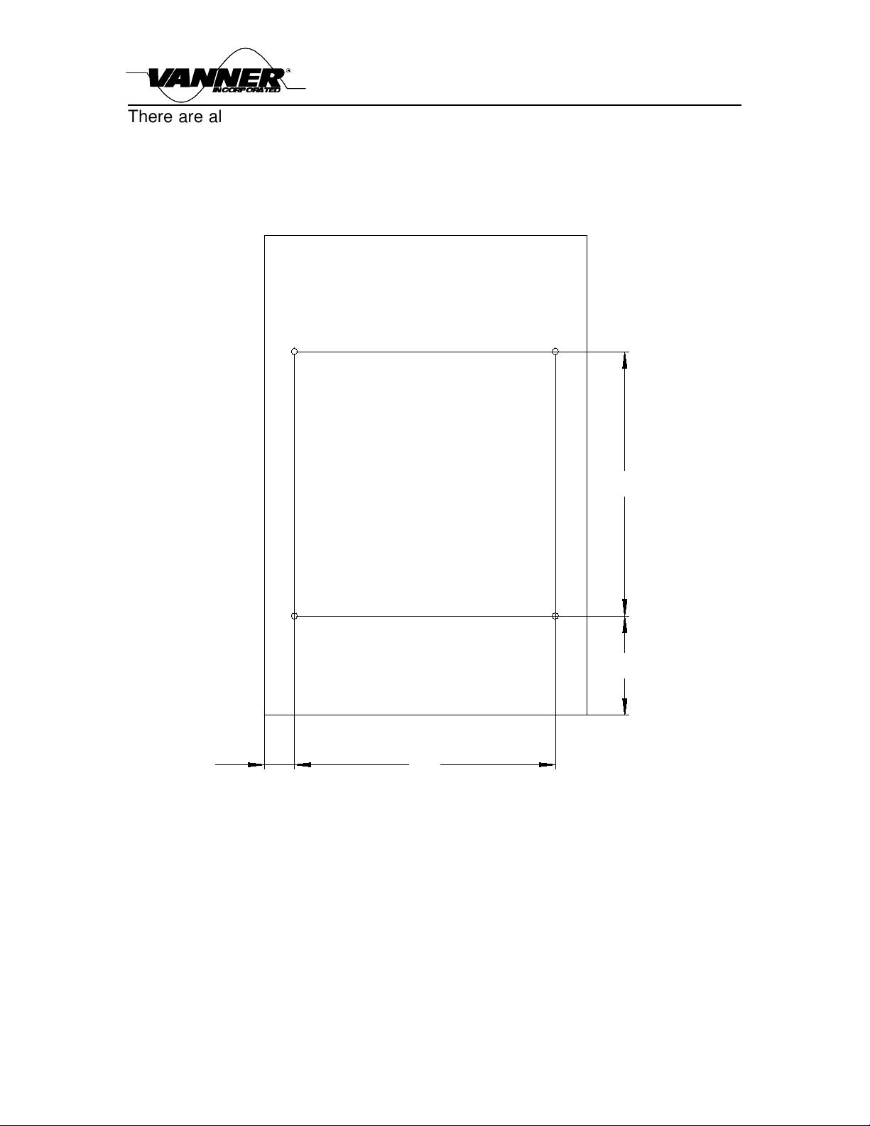
The switches are accessed by removing the 10 metric M4 cover fixing screws (4
on top & 3 down each side) & removing the cover.
WARNING: disconnect the ac input power & wait 5 minutes after switch off,
before removing cover.

Owner's Manual
VCS12/24 Battery Charger
Page 10
The switches locations are as shown below:
heatsink
fan end switches heatsink
ABCD
The switches are the rectangle next to the lower heatsink approximately midway
between the two large transformers.
The 4 ways are designated A through D, left to right, viewed as in the above
diagram.
The charger is supplied with all switches in the “off” position (switched towards
the adjacent heatsink). This sets the output to 24V nominal in charger mode.
To set the output to 12V nominal, charger mode, set switches A & B to the “on”
position (switched away from the adjacent heatsink).
WARNING: switches A & B must always be both “on” or both “off”.
To change from charger mode to power supply mode, set switch C to the “on”
position (switched towards the adjacent heatsink). This operates in both 24V &
12V modes.
Switch D is not used.
WARNING: connecting a 12V battery to the 24V output can cause serious
damage, fire & injury.

Owner's Manual
VCS12/24 Battery Charger
Page 11
8) Internal fuses
8.1) Input fuse.
This is a 1¼” x ¼” 15A 250V UL recognised time delay fuse, mounted in clips
behind the ac input terminals.
In the unlikely event of this fuse blowing, it is strongly recommended that any
faults are investigated & repaired by a competent engineer, before replacing the
fuse & switching on.
Replacing a blown fuse & switching on without investigating the cause can cause
further damage. In any case, the same type & rating of fuse must be used.
8.2) Output fuse.
This is a UL recognised “Littelfuse” 498060 fuse, fixed behind the dc output
terminals by 2 x M5 metric bolts. Its ratings are 60A 32V time delay. The main
purpose of this fuse is to protect against the inadvertent reverse polarity
connection of a battery to the output. If this occurs, a protection device conducts
& blows the fuse to protect the charger. No other damage should occur. Replace
with the same type & rating of fuse.
9) Standards
9.1) Safety.
Designed to meet UL458, Power Converters / Inverters & Power Converter /
Inverter Systems for Land Vehicles & Marine Craft.
9.2) EMI & Immunity.
Designed to meet the requirements of SAE J1113, SAE J1455, EN61000 &
CFR47.

Owner's Manual
VCS12/24 Battery Charger
Page 12
Vanner Incorporated
4282 Reynolds Drive
Hilliard, Ohio 43026
1-800-AC Power
1-800-227-6937
Ph: 614-771-2818
Fax 614-771-4904
www.vanner.com
Owner's Manual Document Part Number D913335-A
April 5, 2006
This manual suits for next models
1
Table of contents
Other Vanner Batteries Charger manuals

Vanner
Vanner SP00143/181 User manual

Vanner
Vanner SP00155 User manual

Vanner
Vanner SP00155 User manual

Vanner
Vanner SP00175 User manual

Vanner
Vanner TruSine TSC24-4500 User manual

Vanner
Vanner SPC0182 User manual

Vanner
Vanner ITC24-360 User manual

Vanner
Vanner Silent Runner SRC12-1100PT User manual

Vanner
Vanner ITC-Series User manual