manuals.online logo
Brands
  1. Home
  2. •
  3. Brands
  4. •
  5. Vega
  6. •
  7. Accessories
  8. •
  9. Vega VEGAPULS 66 User manual

Vega VEGAPULS 66 User manual

Operating Instructions
VEGAPULS 66
Profibus PA
Contents
1About this document
1.1Function ............................. 4
1.2Target group .......................... 4
1.3Symbolism used ....................... 4
2For your safety
2.1Authorised personnel .................... 5
2.2Appropriate use........................ 5
2.3Warning about misuse ................... 5
2.4CE conformity ......................... 5
2.5Fulfils NAMUR recommendations ........... 6
2.6FCC and IC conformity (only for USA/Canada). 6
2.7Safety information for Ex areas............. 7
2.8Manufacturer declaration ................. 7
2.9Functional range of approved instruments ..... 8
2.10 Environmental instructions ................ 8
3Product description
3.1Configuration.......................... 10
3.2Principle of operation.................... 11
3.3Operation ............................ 12
3.4Storage and transport ................... 13
4Mounting
4.1General instructions..................... 14
4.2Mounting information .................... 15
5Connecting to power supply
5.1Preparing the connection ................. 22
5.2Connection steps -Instrument housing ....... 23
5.3Wiring plan,single chamber housing......... 24
5.4Wiring plan,double chamber housing ........ 26
5.5Wiring plan,version IP 66/IP 68,1bar ....... 28
5.6Switch-on phase ....................... 28
6Setup with the indicating and adjustment module
PLICSCOM
6.1Short description ....................... 29
6.2Insert the indicating and adjustment module ... 29
6.3Adjustment system ..................... 31
6.4Setup procedure ....................... 32
6.5Menu schematic ....................... 39
6.6Saving the parameter adjustment data ....... 41
2VEGAPULS 66 -Profibus PA
Contents
28448-EN-060613
7Setup with PACTware™and other adjustment
programs
7.1Connecting the PC ..................... 42
7.2Parameter adjustment with PACTware™...... 42
7.3Parameter adjustment with PDM............ 43
7.4Saving the parameter adjustment data ....... 43
8Maintenance and fault rectification
8.1Maintenance .......................... 44
8.2Fault rectification ....................... 44
8.3Exchange of the electronics ............... 46
8.4Instrument repair ....................... 47
9Dismounting
9.1Dismounting procedure .................. 48
9.2Disposal ............................. 48
10 Supplement
10.1Technical data......................... 49
10.2Profibus PA........................... 59
10.3Dimensions ........................... 64
10.4Industrial property rights.................. 68
Supplementary operating instructions manuals
Information:
VEGAPULS 66 is available in different versions and is
supplied specifically according to the order.Depending on the
selected version,supplementary operating instructions man-
uals are included in the delivery.The supplementary operating
instructions are stated in paragraph "Product description".
Operating instructions manuals for accessories and
replacement parts
Tip:
To ensure reliable setup and operation of your VEGAPULS 66,
VEGA offers accessories and replacement parts.The asso-
ciated documents are:
lOperating instructions manual "External indicating and
adjustment unit VEGADIS 61"
lOperating instructions manual "Oscillator VEGAPULS
series 60"
lSupplementary instructions manual "Flanges according to
DIN-EN-ASME-JIS"
VEGAPULS 66 -Profibus PA 3
Contents
28448-EN-060613
1About this document
1.1Function
This operating instructions manual has all the information you
need for quick setup and safe operation.Please read this
manual before you start setup.
1.2Target group
This operating instructions manual is directed to trained,
qualified personnel.The contents of this manual should be
made available to these personnel and put into practice by
them.
1.3Symbolism used
Information,tip,note
This symbol indicates helpful additional information.
Caution:If this warning is ignored,faults or
malfunctions can result.
Warning:If this warning is ignored,injury to persons and/or
serious damage to the instrument can result.
Danger:If this warning is ignored,serious injury to persons
and/or destruction of the instrument can result.
Ex applications
This symbol indicates special instructions for Ex applications.
lList
The dot set in front indicates a list with no implied sequence.
àAction
This arrow indicates a single action.
1Sequence
Numbers set in front indicate successive steps in a procedure.
4VEGAPULS 66 -Profibus PA
About this document
28448-EN-060613
2For your safety
2.1Authorised personnel
All operations described in this operating instructions manual
must be carried out only by trained specialist personnel
authorised by the operator.For safety and warranty reasons,
any internal work on the instruments must be carried out only
by personnel authorised by the manufacturer.
2.2Appropriate use
VEGAPULS 66 is a sensor for continuous level measurement.
Detailed information on the application range of VEGAPULS
66 is available in chapter "Product description".
2.3Warning about misuse
Inappropriate or incorrect use of the instrument can give rise to
application-specific hazards,e.g.vessel overfill or damage to
system components through incorrect mounting or adjustment.
2.4General safety instructions
VEGAPULS 66 is a high-tech instrument requiring the strict
observance of standard regulations and guidelines.The
emitting frequencies of all radar sensors are in the Cor K-band
range (depending on the instrument version). The low trans-
mitting power is far below the internationally permitted limit
values,and when the instrument is used correctly,no health-
endangering effects are to be expected.There are no
restrictions on using the instrument on the outside of metallic,
closed vessels.The user must take note of the safety
instructions in this operating instructions manual,the country-
specific installation standards (e.g.the VDE regulations in
Germany)as well as all prevailing safety regulations and
accident prevention rules.
2.5CE conformity
VEGAPULS 66 is in CE conformity with EMVG (89/336/EWG),
R&TTE directive (1999/5/EC)and LVD (73/23/EWG).
Conformity has been judged according to the following
standards:
lEMC:EN 61326:2004
VEGAPULS 66 -Profibus PA 5
For your safety
28448-EN-060613
-Emission:Class B
-Susceptibility:Industrial areas
lR&TTE directive:I-ETS 300-440 Expert opinion No.
0043052-01/SEE,Notified Body No.0499
lLVD:EN 61010-1:2002
2.6Fulfils NAMUR recommendations
In respect to interference resistance and emitted interference,
VEGAPULS 66 fulfils NAMUR recommendation NE 21.
VEGAPULS 66 and its indicating/adjustment components fulfill
NAMUR recommendation NE 53 in respect to compatibility.
VEGA instruments are generally upward and downward
compatible:
lSensor software for DTM VEGAPULS 66 HART,PA or FF
lDTM VEGAPULS 66 for adjustment software PACTware™
lIndicating and adjustment module for sensor software
The parameter adjustment of the basic sensor functions is
independent of the software version.The range of available
functions depends on the respective software version of the
individual components.
The software version of VEGAPULS 66 can be determined as
follows:
lvia PACTware™
lon the type label of the electronics
lvia the indicating and adjustment module
You can view all software histories on our website www.vega.
com.Make use of this advantage and get registered for update
information via e-mail.
2.7FCC and IC conformity (only for USA/Canada)
VEGAPULS 66 is FCC and IC approved:
lFCC ID:O6QPULS6566
lIC:3892A-PS6566
Modifications not expressly approved by VEGA will lead to
expiry of the operating licence according to FCC.
VEGAPULS 66 is in conformity with part 15 of the FCC
regulations.Take note of the respective operating regulations:
lThe instrument must not cause any interfering emissions
6VEGAPULS 66 -Profibus PA
For your safety
28448-EN-060613
lThe instrument must be insensitive to interfering emis-
sions,also to such that may cause unwanted operating
conditions.
VEGAPULS 66 was tested and meets the limit values for a
digital instrument of class B,according to part 15 of the FCC
regulations.The limit values are for protection against
interfering emissions during operation in industrial environ-
ment.
The instrument can generate,use and emit high frequency
energy and can generate interfering emissions if not used as
described in the operator's manual.Because interfering
emissions have to be reckoned with when the instrument is
used in residential areas,the user must make sure necessary
countermeasures are implemented.
2.8Safety information for Ex areas
Please note the Ex-specific safety information for installation
and operation in Ex areas.These safety instructions are part of
the operating instructions manual and come with the Ex-
approved instruments.
2.9Manufacturer declaration
In conformity with DIN EN 60079-14/2004,para.5.2.3,point
c1,VEGAPULS 66 is suitable for use in zone 2.
The operator must use the instrument as it was intended to be
used and follow the specifications of the following documents:
lthis operating instructions manual
lthis manufacturer declaration (24627)
lthe corresponding installation regulations
Max.increase of the surface temperature during operation:
15 K(individual components in the instrument)
With an ambient temperature of 70 °C(158 °F)on the housing
and a process temperature of 70 °C(158 °F), the max.ambient
temperature during operation is 85 °C(185 °F).
Measures for maintaining explosion protection during oper-
ation:
lThe instrument must be connected and operated on a
Profibus DP/PA segment coupler or a VEGALOG 571 EP
card.
VEGAPULS 66 -Profibus PA 7
For your safety
28448-EN-060613
lOperate the instrument in the range of the specified
electrical limit values.Permissible supply voltage:see
"Technical data"
lMount and operate the instrument in such a way that no
danger of ignition by electrostatic charges is to be
expected.Antenna,process fitting and housing (as the
case may be depending on instrument version)are made
of electrically non-conductive plastic.
lMake sure that the seal is mounted correctly between the
lower part of the housing and the cover.Screw the cover
on tightly.
lMake sure there is no explosive atmosphere present if you
intend to operate the instrument with opened cover
lMake sure that the cable gland is tight and strain-relieved.
The outer diameter of the connection cable must be
adapted to the cable gland.Tighten the pressure screw of
the cable gland carefully.
lCover unused openings for cable glands tightly
lMount the instrument in such a way that the sensor cannot
touch the vessel wall or vessel installations.Keep in mind
the influence of product movement in the vessel.
lThe surface temperature of the housing must not exceed
the ignition temperature of the surrounding explosive
atmosphere
This instrument was assessed by a person who fulfils the DIN
EN 60079-14 requirements.
2.10 Functional range of approved instruments
Instruments with StEx,WHG or ship approval as well as
national approvals such as according to FM or CSA are partly
supplied with a previous hardware or software version.For
approval-technical reasons,some functions for these instru-
ments will be only available at a later date.
You can find relevant information in the individual function
descriptions in this operating instructions manual.
2.11 Environmental instructions
Protection of the environment is one of our most important
duties.That is why we have introduced an environment
management system with the goal of continuously improving
company environmental protection.The environment man-
agement system is certified according to DIN EN ISO 14001.
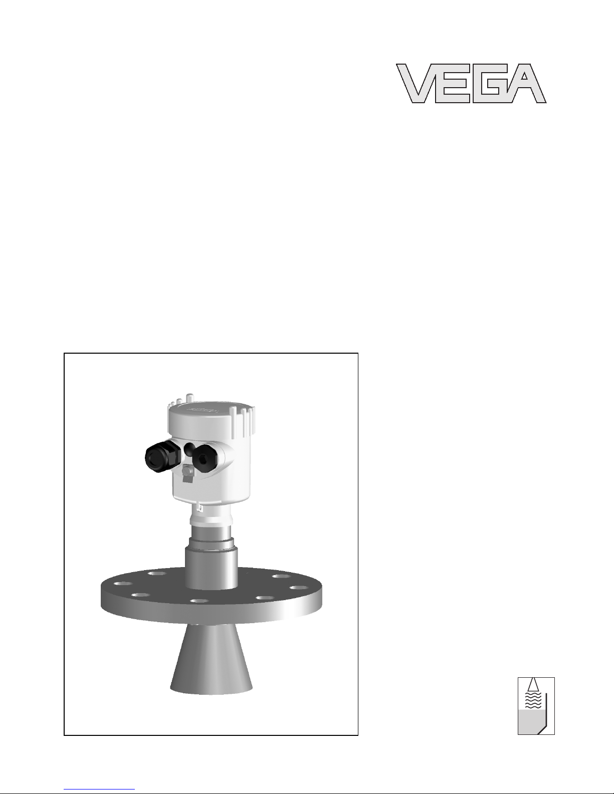
8VEGAPULS 66 -Profibus PA
For your safety
28448-EN-060613
Please help us fulfil this obligation by observing the environ-
mental instructions in this manual:
lChapter "Storage and transport"
lChapter "Disposal"
VEGAPULS 66 -Profibus PA 9
For your safety
28448-EN-060613
3Product description
3.1Configuration
The scope of delivery encompasses:
lVEGAPULS 66 radar sensor
lDocumentation
-this operating instructions manual
-Operating instructions manual "Indicating and adjust-
ment module PLICSCOM"(optional)
-Supplementary instructions manual "Heating for indi-
cating and adjustment module PLICSCOM"(optional)
-Supplementary instructions manual "Plug connector for
continuously measuring sensors"(optional)
-Ex-specific"Safety instructions"(with Ex versions)
-if necessary,further certificates
VEGAPULS 66 consists of the following components:
lProcess fitting with antenna system
lHousing with electronics,optionally available with plug
connector,optionally available with connection cable
lHousing cover,optionally available with indicating and
adjustment module PLICSCOM
The components are available in different versions.
Scope of delivery
Components
10 VEGAPULS 66 -Profibus PA
Product description
28448-EN-060613
3
2
1
Fig.1:VEGAPULS 66,flange version with plastic housing
1Housing cover with integrated PLICSCOM (optional)
2Housing with electronics
3Process fitting with antenna system
3.2Principle of operation
VEGAPULS 66 is a radar sensor in C-band (emitting frequency
approx.6GHz)for continuous level measurement.
Aspecial version of VEGAPULS 66 is available for each area
of application.The version with flange and horn antenna is
particularly suitable for measurement of liquids and solids
under extremely difficult process conditions such as buildup,
condensate and foam generation as well as vigorous product
movement.
With the version without antenna horn,the antenna system
is formed in conjunction with a measuring tube (surge or
bypass tube). This version is particularly suitable for meas-
urement of solvents and liquid gases.
For pressures up to 160 bar (2320 psi)and temperatures up to
400 °C(752 °F), the graphite seal and the ceramic antenna
cone are available.
The antenna of the radar sensor emits short radar pulses with
a duration of approx.1ns.These pulses are reflected by the
product and received by the antenna as echoes.The running
time of the radar pulses from emission to reception is
Area of application
Physical principle
VEGAPULS 66 -Profibus PA 11
Product description
28448-EN-060613
proportional to the distance and hence to the level.The
determined level is converted into an appropriate output signal
and outputted as measured value.
Power is supplied via the Profibus DP/PA segment coupler or
VEGALOG 571 EP cards.Atwo-wire cable according to
Profibus specification serves as carrier of both power and
digital data signals for multiple sensors.The instrument profile
of VEGAPULS 66 corresponds to profile specification version
3.0.
The GSD (instrument master files)and bitmap files necessary
for planning your Profibus-DP-(PA)communication network
are available from the download section on the VEGA
homepage www.vega.com under "Services -Downloads -
Software -Profibus".There you can also find the appropriate
certificates.InaPDM environment,an EDD (Electronic Device
Description)is also required to enable the full range of sensor
functions (also available as a download).ACDwith the
appropriate files can be ordered via e-mail under info@de.
vega.com or by phone from one of the VEGA agencies under
the order number "DRIVER.S".
The backlight of the indicating and adjustment module
PLICSCOM is powered by the sensor.The prerequisite for this
is a supply voltage at a certain level.The exact voltage
specifications are stated in the "Technical data"in the
"Supplement".
This function is for instruments with StEx,WHG or ship
approval as well as country-specific approvals such as those
according to FM or CSA,available at a later date.
The optional heating requires its own power supply.You can
find further details in the supplementary instructions manual
"Heating for indicating and adjustment module PLICSCOM".
This function is generally not available for approved instru-
ments.
3.3Operation
VEGAPULS 66 can be adjusted with three different adjustment
media:
lthe indicating and adjustment module PLICSCOM
lthe suitable VEGA DTM in conjunction with an adjustment
software according to the FDT/DTM standard,e.g.
PACTware™and PC
Power supply and bus com-
munication
GSD/EDD
12 VEGAPULS 66 -Profibus PA
Product description
28448-EN-060613
lthe Simatic adjustment program PDM
The entered parameters are generally saved in VEGAPULS
66,optionally also in PLICSCOM or in PACTware™.
3.4Storage and transport
Your instrument was protected by packaging during transport.
Its capacity to handle normal loads during transport is assured
by a test according to DIN EN 24180.
The packaging of standard instruments consists of environ-
ment-friendly,recyclable cardboard.For special versions,PE
foam or PE foil is also used.Dispose of the packaging material
via specialised recycling companies.
lStorage and transport temperature see "Supplement -
Technical data -Ambient conditions"
lRelative humidity 20 …85 %
Packaging
Storage and transport tem-
perature
VEGAPULS 66 -Profibus PA 13
Product description
28448-EN-060613
4Mounting
4.1General instructions
Select an installation position you can easily reach for
mounting and connecting as well as later retrofitting of an
indicating and adjustment module.The housing can be rotated
by 330°without the use of any tools.You can also install the
indicating and adjustment module in four different positions
(each displaced by 90°).
Use the recommended cables (see chapter "Connecting to
power supply")and tighten the cable gland.
You can give your VEGAPULS 66 additional protection against
moisture penetration by leading the connection cable down-
ward in front of the cable entry.Rain and condensation water
can thus drain off.This applies mainly to mounting outdoors,in
areas where moisture is expected (e.g.by cleaning processes)
or on cooled or heated vessels.
Fig.2:Measures against moisture penetration
The reference plane for the measuring range is the lower edge
of the flange or the seal surface of the thread.
Information:
If the medium reaches the antenna,buildup can form on it and
cause faulty measurements later on.
Installation position
Moisture
Measuring range
14 VEGAPULS 66 -Profibus PA
Mounting
28448-EN-060613
1 32
100%
0%
4
Fig.3:Measuring range (operating range)and max.measuring distance
1full
2empty (max.measuring distance)
3Measuring range
Make sure that the wetted parts of VEGAPULS 66,especially
the seal and process fitting,are suitable for the existing
process conditions such as pressure,temperature etc.as well
as the chemical properties of the medium.
You will find specification in chapter "Technical data"in the
"Supplement".
4.2Mounting information
Mount VEGAPULS 66 at least 500 mm (19.7in)from the
vessel wall.If the sensor is installed in the center of vessels
with dished or round tops,multiple echoes can arise.These
can,however,be suppressed by an appropriate adjustment
(see "Setup").
If this distance cannot be maintained,a false echo storage
should be carried out during setup.This applies particularly if
buildup on the vessel wall is expected.In such case,we
recommend repeating the false echo storage later on with
existing buildup.
Materials,wetted parts
Mounting position
VEGAPULS 66 -Profibus PA 15
Mounting
28448-EN-060613
1
2
> 500 mm
Fig.4:Mounting on round vessel tops
1Reference plane
2Vessel center or symmetry axis
In vessels with conical vessel bottom it can be advantageous
to mount the sensor in the center of the vessel,as measure-
ment is then possible down to the lowest point of the vessel
bottom.
Fig.5:Vessel with conical bottom
Do not mount the instruments in or above the filling stream.
Make sure that you detect the product surface and not the
inflowing product.
Inflowing material
16 VEGAPULS 66 -Profibus PA
Mounting
28448-EN-060613
Fig.6:Inflowing liquid
Socket pieces should be dimensioned such that the antenna
end protrudes at least 10 mm (0.4in)out of the socket.
ca. 10 mm
Fig.7:Recommended socket mounting
If the socket height cannot be maintained,an antenna
extension will be necessary.This prevents from false
reflections of the socket piece.
Socket
VEGAPULS 66 -Profibus PA 17
Mounting
28448-EN-060613
ca. 10 mm
Fig.8:Tube extension
Tip:
VEGAPULS 66 is optionally also available with antenna
extension.Hence the antenna length can be selected such
that the antenna end protrudes 10 mm (0.4in)out of the
socket.
In liquids,direct the sensor as perpendicular as possible to the
product surface to achieve an optimum measurement.
Fig.9:Orientation in liquids
The radar sensor should be installed at a location where no
installations cross the radar signals.
Vessel installations such as,for example,ladders,limit
switches,heating spirals,struts,etc.can cause false echoes
that get superimposed on the useful echo.Make sure when
planning your measuring site that the radar sensor has a "clear
view"to the measured product.
If there are existing vessel installations,a false echo storage
should be carried out during setup.
Sensor orientation
Vessel installations
18 VEGAPULS 66 -Profibus PA
Mounting
28448-EN-060613
If large vessel installations such as struts or supports cause
false echoes,these can be attenuated through supplementary
measures.Small,inclined sheet metal baffles above the
installations scatter the radar signals and prevent direct
interfering reflections.
Fig.10:Cover smooth profiles with deflectors
If there are agitators in the vessel,a false echo storage should
be carried out with the agitators in motion.This ensures that
the interfering reflections from the agitators are saved with the
blades in different positions.
Fig.11:Agitators
Through the action of filling,stirring and other processes in the
vessel,dense foams which considerably damp the emitted
signals may form on the product surface.
If foams are causing measurement errors,the biggest possible
radar antenna should be used.
Agitators
Foam generation
VEGAPULS 66 -Profibus PA 19
Mounting
28448-EN-060613
VEGAFLEX sensors with guided microwaves are not influ-
enced by foam generation and are particularly suitable for such
applications.
By using a standpipe,the influence of vessel installations and
turbulence can be excluded.Under these prerequisites,the
measurement of products with low dielectric values (from DK
value 1.6)is possible.
Surge or bypass tubes must extend all the way down to the
requested min.level,as measurement is only possible within
the tube.
max.
min.
2
1
Fig.12:Pipe antenna systems in a tank
1Marking of the polarisation direction
2Ventilation hole max.ø5mm (0.2in)
If possible,the diameter of the sensor antenna should
correspond to the inner diameter of the tube.With VEGAPULS
66 this is approx.50 mm (2in)depending on the antenna.The
sensor can be used with tube diameters between 50 …250 mm
(2…10 in).
Make sure you provide the necessary upper vent hole in the
surge pipe,which must by displaced by 90°to the polarisation
marking on the sensor flange (see illustration:"Pipe antenna
system in a tank").
As an alternative to the surge pipe in the vessel,a pipe system
can be mounted outside of the vessel as a bypass tube.For
setup,select the function "Bypass tube".
Measurement in the stand-
pipe (surge or bypass tube)
20 VEGAPULS 66 -Profibus PA
Mounting
28448-EN-060613

Other manuals for VEGAPULS 66

17

Other Vega Accessories manuals

Vega VEGAPULS 65 User manual

Vega

Vega VEGAPULS 65 User manual

Vega VEGAPULS 69 User manual

Vega

Vega VEGAPULS 69 User manual

Vega VEGAPULS 68 User manual

Vega

Vega VEGAPULS 68 User manual

Vega SMART-MC0101 User manual

Vega

Vega SMART-MC0101 User manual

Vega VEGAPULS 69 User manual

Vega

Vega VEGAPULS 69 User manual

Vega VEGAFLEX 82 User manual

Vega

Vega VEGAFLEX 82 User manual

Vega VEGAFLEX 86 User manual

Vega

Vega VEGAFLEX 86 User manual

Vega VEGAPULS C 22 User manual

Vega

Vega VEGAPULS C 22 User manual

Vega VEGAPULS 67 User manual

Vega

Vega VEGAPULS 67 User manual

Vega VEGABAR 28 User manual

Vega

Vega VEGABAR 28 User manual

Vega VEGAPULS WL S 61 User manual

Vega

Vega VEGAPULS WL S 61 User manual

Vega VEGAFLEX 65 User manual

Vega

Vega VEGAFLEX 65 User manual

Vega vegaplus sr 68 User manual

Vega

Vega vegaplus sr 68 User manual

Vega VEGAPULS 67 User manual

Vega

Vega VEGAPULS 67 User manual

Vega VEGAFLEX 81 User manual

Vega

Vega VEGAFLEX 81 User manual

Vega VEGAPULS 61 User manual

Vega

Vega VEGAPULS 61 User manual

Vega VEGAPULS WL 61 User manual

Vega

Vega VEGAPULS WL 61 User manual

Vega VEGAFLEX 82 User manual

Vega

Vega VEGAFLEX 82 User manual

Vega VEGAFLEX 65 User manual

Vega

Vega VEGAFLEX 65 User manual

Vega VEGACAP 63 User manual

Vega

Vega VEGACAP 63 User manual

Vega vegaflex 83 User manual

Vega

Vega vegaflex 83 User manual

Vega VEGADIS 81 User manual

Vega

Vega VEGADIS 81 User manual

Vega POINTRAC 31 User manual

Vega

Vega POINTRAC 31 User manual

Vega VEGAFLEX 81 User manual

Vega

Vega VEGAFLEX 81 User manual

Popular Accessories manuals by other brands

Byron DIC-24815 instruction manual

Byron

Byron DIC-24815 instruction manual

Yaohua Weighing System XK3190-A12 user manual

Yaohua Weighing System

Yaohua Weighing System XK3190-A12 user manual

Philips DLA7575H brochure

Philips

Philips DLA7575H brochure

WiT WT901BLE user manual

WiT

WiT WT901BLE user manual

Samsung RT4401-48A installation manual

Samsung

Samsung RT4401-48A installation manual

OHAUS Defender 3000 instruction manual

OHAUS

OHAUS Defender 3000 instruction manual

Saxby Lighting 94057 instruction manual

Saxby Lighting

Saxby Lighting 94057 instruction manual

Excalibur BurpMaster Keychain 112-SG user guide

Excalibur

Excalibur BurpMaster Keychain 112-SG user guide

Thule Fiamma instructions

Thule

Thule Fiamma instructions

Malmbergs Dual sense DALI 99 190 23 Installation and instruction manual

Malmbergs

Malmbergs Dual sense DALI 99 190 23 Installation and instruction manual

Bryant Preferred Series Service and maintenance instructions

Bryant

Bryant Preferred Series Service and maintenance instructions

Venstar ACC-FP1xx installation instructions

Venstar

Venstar ACC-FP1xx installation instructions

Audiotrak AUDIOTRAK MAYA44 user guide

Audiotrak

Audiotrak AUDIOTRAK MAYA44 user guide

dinacell OMEGA NG user manual

dinacell

dinacell OMEGA NG user manual

Huawei Alita-CB010 quick start guide

Huawei

Huawei Alita-CB010 quick start guide

Wasserstein Smart Water Sensor user manual

Wasserstein

Wasserstein Smart Water Sensor user manual

Philips HF3520/01B user manual

Philips

Philips HF3520/01B user manual

Wenglor UMS603U035 operating instructions

Wenglor

Wenglor UMS603U035 operating instructions

manuals.online logo
manuals.online logoBrands
  • About & Mission
  • Contact us
  • Privacy Policy
  • Terms and Conditions

Copyright 2025 Manuals.Online. All Rights Reserved.