Vega VEGAPULS 69 User manual

Operating Instructions
Radar sensor for continuous level
measurement of bulk solids
VEGAPULS 69
4 … 20 mA/HART - two-wire
Document ID: 47247

2
Contents
VEGAPULS 69 • 4 … 20 mA/HART - two-wire
47247-EN-150211
Contents
1 About this document
1.1 Function ........................................................................................................................... 4
1.2 Target group ..................................................................................................................... 4
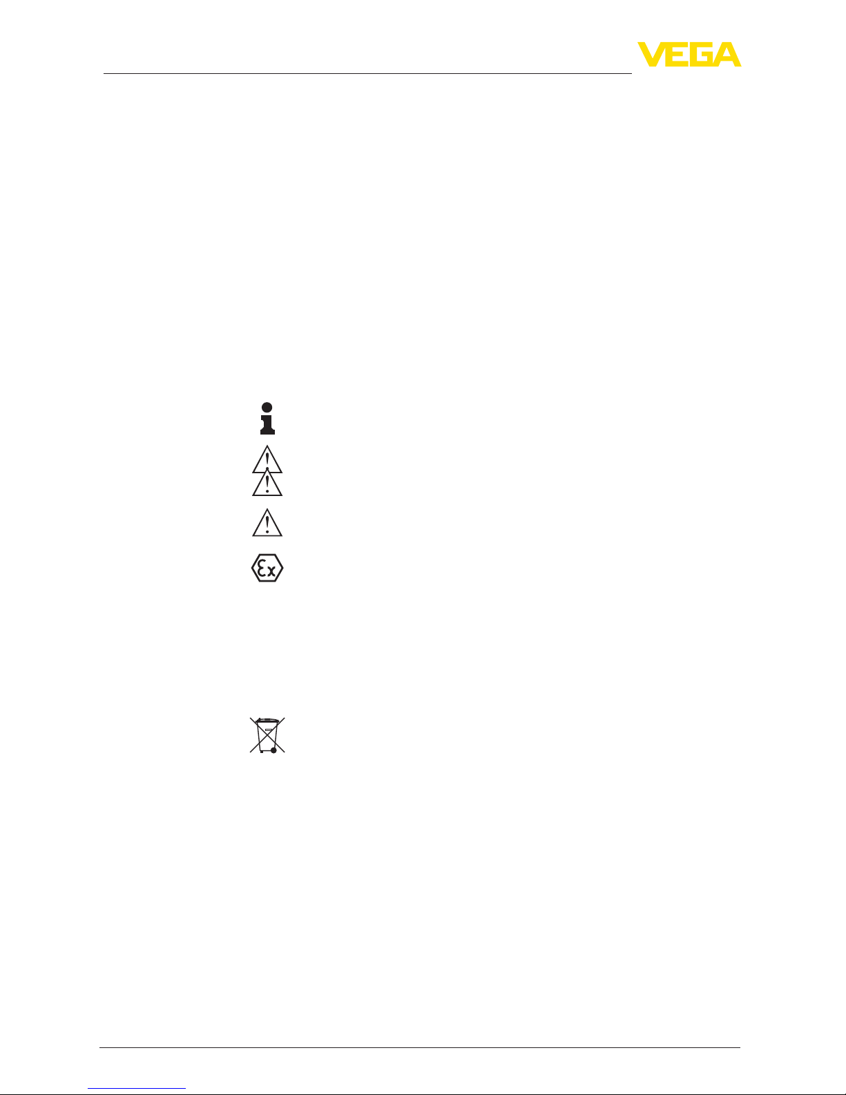
1.3 Symbols used................................................................................................................... 4
2 For your safety
2.1 Authorised personnel ....................................................................................................... 5
2.2 Appropriate use................................................................................................................ 5
2.3 Warning about incorrect use............................................................................................. 5
2.4 General safety instructions............................................................................................... 5
2.5 CE conformity................................................................................................................... 6
2.6 NAMUR recommendations .............................................................................................. 6
2.7 Radio license for Europe .................................................................................................. 6
2.8 Environmental instructions ............................................................................................... 6
3 Product description
3.1 Conguration.................................................................................................................... 8
3.2 Principle of operation........................................................................................................ 9
3.3 Packaging, transport and storage................................................................................... 10
3.4 Accessories and replacement parts ............................................................................... 10
4 Mounting
4.1 General instructions ....................................................................................................... 13
4.2 Mounting versions, plastic horn antenna ........................................................................ 13
4.3 Mounting preparations, mounting strap.......................................................................... 16
4.4 Mounting instructions ..................................................................................................... 17
5 Connecting to power supply
5.1 Preparing the connection ............................................................................................... 28
5.2 Connecting..................................................................................................................... 29
5.3 Wiring plan, single chamber housing.............................................................................. 30
5.4 Wiring plan, double chamber housing ............................................................................ 31
5.5 Double chamber housing Ex d ....................................................................................... 33
5.6 Wiring plan, double chamber housing Ex d ia ................................................................ 34
5.7 Double chamber housing with DIS-ADAPT .................................................................... 36
5.8 Wiring plan - version IP 66/IP 68, 1 bar........................................................................... 37
5.9 Switch-on phase............................................................................................................. 37
6 Set up with the display and adjustment module
6.1 Insert display and adjustment module............................................................................ 38
6.2 Adjustment system......................................................................................................... 39
6.3 Measured value indication - Selection national language............................................... 40
6.4 Parameter adjustment - Quick setup .............................................................................. 41
6.5 Parameter adjustment - Extended adjustment................................................................ 42
6.6 Saving the parameter adjustment data........................................................................... 56
7 Setup with PACTware
7.1 Connect the PC.............................................................................................................. 58
7.2 Parameter adjustment .................................................................................................... 59
7.3 Saving the parameter adjustment data........................................................................... 60
8 Set up with other systems

3
Contents
VEGAPULS 69 • 4 … 20 mA/HART - two-wire
47247-EN-150211
8.1 DD adjustment programs ............................................................................................... 61
8.2 Field Communicator 375, 475 ........................................................................................ 61
9 Diagnosis, asset management and service
9.1 Maintenance .................................................................................................................. 62
9.2 Measured value and event memory ............................................................................... 62
9.3 Asset Management function........................................................................................... 63
9.4 Rectify faults................................................................................................................... 67
9.5 Exchanging the electronics module................................................................................ 70
9.6 Software update ............................................................................................................. 71
9.7 How to proceed if a repair is needed.............................................................................. 71
10 Dismount
10.1 Dismounting steps.......................................................................................................... 72
10.2 Disposal ......................................................................................................................... 72
11 Supplement
11.1 Technical data ................................................................................................................ 73
11.2 Radio astronomy stations............................................................................................... 82
11.3 Dimensions .................................................................................................................... 82
Safety instructions for Ex areas
TakenoteoftheExspecicsafetyinstructionsforExapplications.
These instructions are attached as documents to each instrument
with Ex approval and are part of the operating instructions manual.
Editing status:2015-01-28

4
1 About this document
VEGAPULS 69 • 4 … 20 mA/HART - two-wire
47247-EN-150211
1 About this document
1.1 Function
This operating instructions manual provides all the information you
need for mounting, connection and setup as well as important instruc-
tionsformaintenanceandfaultrectication.Pleasereadthisinforma-
tion before putting the instrument into operation and keep this manual
accessible in the immediate vicinity of the device.
1.2 Target group
This operating instructions manual is directed to trained specialist
personnel.The contents of this manual should be made available to
these personnel and put into practice by them.
1.3 Symbols used
Information, tip, note
This symbol indicates helpful additional information.
Caution: If this warning is ignored, faults or malfunctions can result.
Warning: If this warning is ignored, injury to persons and/or serious
damage to the instrument can result.
Danger: If this warning is ignored, serious injury to persons and/or
destruction of the instrument can result.
Ex applications
This symbol indicates special instructions for Ex applications.
• List
The dot set in front indicates a list with no implied sequence.
→ Action
This arrow indicates a single action.
1 Sequence of actions
Numbers set in front indicate successive steps in a procedure.
Battery disposal
This symbol indicates special information about the disposal of bat-
teries and accumulators.

5
2 For your safety
VEGAPULS 69 • 4 … 20 mA/HART - two-wire
47247-EN-150211
2 For your safety
2.1 Authorised personnel
All operations described in this operating instructions manual must
be carried out only by trained specialist personnel authorised by the
plant operator.
During work on and with the device the required personal protective
equipment must always be worn.
2.2 Appropriate use
VEGAPULS 69 is a sensor for continuous level measurement.
Youcannddetailedinformationabouttheareaofapplicationin
chapter "Product description".
Operational reliability is ensured only if the instrument is properly
usedaccordingtothespecicationsintheoperatinginstructions
manual as well as possible supplementary instructions.
2.3 Warning about incorrect use
Inappropriate or incorrect use of the instrument can give rise to
application-specichazards,e.g.vesseloverllordamagetosystem
components through incorrect mounting or adjustment.
2.4 General safety instructions
This is a state-of-the-art instrument complying with all prevailing
regulations and guidelines. The instrument must only be operated in a
technicallyawlessandreliablecondition.Theoperatorisresponsible
for the trouble-free operation of the instrument.
During the entire duration of use, the user is obliged to determine the
compliance of the necessary occupational safety measures with the
current valid rules and regulations and also take note of new regula-
tions.
The safety instructions in this operating instructions manual, the na-
tional installation standards as well as the valid safety regulations and
accident prevention rules must be observed by the user.
For safety and warranty reasons, any invasive work on the device
beyond that described in the operating instructions manual may be
carried out only by personnel authorised by the manufacturer. Arbi-
traryconversionsormodicationsareexplicitlyforbidden.
The safety approval markings and safety tips on the device must also
be observed.
Depending on the instrument version, the emitting frequencies are in
the C, K or W band range.The low emitting frequencies are far below
the internationally approved limit values.When used correctly, there is
no danger to health.

6
2 For your safety
VEGAPULS 69 • 4 … 20 mA/HART - two-wire
47247-EN-150211
2.5 CE conformity
ThedevicefulllsthelegalrequirementsoftheapplicableECguide-
lines.ByaxingtheCEmarking,weconrmsuccessfultestingofthe
product.
YoucanndtheCECerticateofConformityinthedownloadsection
of our homepage.
2.6 NAMUR recommendations
NAMUR is the automation technology user association in the process
industry in Germany. The published NAMUR recommendations are
acceptedasthestandardineldinstrumentation.
ThedevicefulllstherequirementsofthefollowingNAMURrecom-
mendations:
• NE 21 – Electromagnetic compatibility of equipment
• NE 43 – Signal level for malfunction information from measuring
transducers
• NE53–Compatibilityofelddevicesanddisplay/adjustment
components
• NE107–Self-monitoringanddiagnosisofelddevices
For further information see www.namur.de.
2.7 Radio license for Europe
The instrument meets the LPR (Level Probing Radar) radio standard
EN 302729-1/2.
It is approved for unrestricted use inside and outside of closed ves-
sels in countries of the EU and EFTA that have implemented this
standard.
For operation outside of closed vessels, the following conditions must
befullled:
• Theinstallationmustbecarriedoutbytrainedqualiedpersonnel
• The instrument must be stationary mounted and the antenna
directed vertically downward
• The mounting location must be at least 4 km away from the radio
astronomy stations, unless special permission was granted by the
responsible national approval authority
• When installed within 4 to 40 km of a radio astronomy station,
the instrument must not be mounted higher than 15 m above the
ground.
Youcanndalistwiththerespectiveradioastronomystationsin
chapter "Supplement".
2.8 Environmental instructions
Protection of the environment is one of our most important duties.
That is why we have introduced an environment management system
with the goal of continuously improving company environmental pro-
tection.Theenvironmentmanagementsystemiscertiedaccording
to DIN EN ISO 14001.

7
2 For your safety
VEGAPULS 69 • 4 … 20 mA/HART - two-wire
47247-EN-150211
Pleasehelpusfulllthisobligationbyobservingtheenvironmental
instructions in this manual:
• Chapter "Packaging, transport and storage"
• Chapter "Disposal"

8
3 Product description
VEGAPULS 69 • 4 … 20 mA/HART - two-wire
47247-EN-150211
3 Product description
3.1 Conguration
Thetypelabelcontainsthemostimportantdataforidenticationand
use of the instrument:
2
1
14
15
13
12
11
5
6
4
3
7
8
9
10
Fig. 1: Layout of the type label (example)
1 Instrument type
2 Product code
3 Approvals
4 Power supply and signal output, electronics
5 Protection rating
6 Measuring range
7 Process and ambient temperature, process pressure
8 Material, wetted parts
9 Hardware and software version
10 Order number
11 Serial number of the instrument
12 Data-Matrix-Code for Smartphone-App
13 Symbol of the device protection class
14 ID numbers, instrument documentation
15 Reminder to observe the instrument documentation
16 NotiedauthorityforCEmarking
17 Approval directive
The type label contains the serial number of the instrument. With it
youcanndthefollowinginstrumentdataonourhomepage:
• Product code (HTML)
• Delivery date (HTML)
• Order-specicinstrumentfeatures(HTML)
• Operating instructions and quick setup guide at the time of ship-
ment (PDF)
• Order-specicsensordataforanelectronicsexchange(XML)
• Testcerticate(PDF)-optional
Go to www.vega.com, "VEGATools" and "Instrument search". Enter
the serial number.
Alternatively, you can access the data via your smartphone:
Type label
Serial number - Instru-
ment search

9
3 Product description
VEGAPULS 69 • 4 … 20 mA/HART - two-wire
47247-EN-150211
• Download the smartphone app "VEGATools" from the "Apple App
Store" or the "GooglePlayStore"
• Scan the Data Matrix code on the type label of the instrument or
• Enter the serial number manually in the app
This operating instructions manual applies to the following instrument
versions:
• Hardware version from 1.0.0
• Software version from 1.0.1
The scope of delivery encompasses:
• Radar sensor
• Hexagon socket wrench (for instruments with swivel holder)
• Documentation
– Quick setup guide VEGAPULS 69
– Instructions for optional instrument features
– Ex-specic"Safety instructions" (with Ex versions)
– ifnecessary,furthercerticates
• DVD "Software & Documents", containing
– Operating instructions
– Safety instructions
– PACTware/DTM-Collection
– Driver software
Information:
In this operating instructions manual, the optional instrument features
are described.The respective scope of delivery results from the order
specication.
3.2 Principle of operation
The VEGAPULS 69 is a radar sensor for continuous level measure-
mentofbulksolidsevenunderthemostdicultprocessconditions
and in wide measuring ranges.
Itisidealforuseinhigh,slendersilos,withpoorlyreectingbulk
solidssuchasyash,plasticgranulesorwoodchipsaswellasstrong
falsereectionsfrominternalinstallations.Thisismadepossible
through the functional principle, a distance measurement through
frequency shifting with a particularly small beam angle.
Theinstrumentisavailablewithdierentantennasystemsandacces-
sories for virtually all applications and processes:
• Plastic horn antenna or metal jacketed lens antenna
• Optional or integrated rinsing air connection
• Swivelling holder with seal against the process
The instrument emits a continuous radar signal via its antenna.This
signal is frequency modulated with a sawtooth form.The emitted
signalisreectedbythemediumandreceivedbytheantennaasan
echo.
Scope of this operating
instructions manual
Scope of delivery
Application area
Functional principle

10
3 Product description
VEGAPULS 69 • 4 … 20 mA/HART - two-wire
47247-EN-150211
The frequency of the received signal always deviates from the actual
emittingfrequency.Thefrequencydierenceisproportionaltothe
distanceandthustothellingheight.Thisdierenceiscalculated
viaspecialalgorithmsinthesensorelectronics.Thedeterminedll-
ing height is then converted into a corresponding output signal and
outputted as the measured value.
3.3 Packaging, transport and storage
Your instrument was protected by packaging during transport. Its
capacity to handle normal loads during transport is assured by a test
based on ISO 4180.
The packaging of standard instruments consists of environment-
friendly, recyclable cardboard. For special versions, PE foam or PE
foil is also used. Dispose of the packaging material via specialised
recycling companies.
Transport must be carried out in due consideration of the notes on the
transport packaging. Nonobservance of these instructions can cause
damage to the device.
The delivery must be checked for completeness and possible transit
damage immediately at receipt. Ascertained transit damage or con-
cealed defects must be appropriately dealt with.
Up to the time of installation, the packages must be left closed and
stored according to the orientation and storage markings on the
outside.
Unless otherwise indicated, the packages must be stored only under
the following conditions:
• Not in the open
• Dry and dust free
• Not exposed to corrosive media
• Protected against solar radiation
• Avoiding mechanical shock and vibration
• Storage and transport temperature see chapter "Supplement -
Technicaldata-Ambientconditions"
• Relative humidity 20 … 85 %
3.4 Accessories and replacement parts
The display and adjustment module PLICSCOM is used for measured
value indication, adjustment and diagnosis. It can be inserted into the
sensor or the external display and adjustment unit and removed at
any time.
Youcanndfurtherinformationintheoperatinginstructions"Display
and adjustment module PLICSCOM" (Document-ID 27835).
The interface adapter VEGACONNECT enables the connection of
communication-capable instruments to the USB interface of a PC. For
Packaging
Transport
Transport inspection
Storage
Storage and transport
temperature
PLICSCOM
VEGACONNECT

11
3 Product description
VEGAPULS 69 • 4 … 20 mA/HART - two-wire
47247-EN-150211
parameter adjustment of these instruments, the adjustment software
PACTware with VEGA-DTM is required.
Youcanndfurtherinformationintheoperatinginstructions"Interface
adapterVEGACONNECT" (Document-ID 32628).
The VEGADIS 81 is an external display and adjustment unit for VEGA
plics®sensors.
For sensors with double chamber housing the interface adapter
"DISADAPT" is also required for VEGADIS 81.
Youcanndfurtherinformationintheoperatinginstructions"VE-
GADIS81" (Document-ID 43814).
The adapter "DISADAPT" is an accessory part for sensors with dou-
ble chamber housings. It enables the connection of VEGADIS 81 to
the sensor housing via an M12 x 1 plug.
Youcanndfurtherinformationinthesupplementaryinstructions
"AdapterDISADAPT" (Document-ID 45250).
VEGADIS 82 is suitable for measured value indication and adjustment
of sensors with HART protocol. It is looped into the 4 … 20 mA/HART
signal cable.
Youcanndfurtherinformationintheoperatinginstructions"VE-
GADIS82" (Document-ID 45300).
PLICSMOBILE T61 is an external GSM/GPRS radio unit for transmis-
sion of measured values and for remote parameter adjustment of
plics®sensors. Adjustment is carried out via PACTware/DTM and the
integrated USB connection.
Youcanndfurtherinformationinthesupplementaryinstructions
"PLICSMOBILET61" (Document-ID 37700).
PLICSMOBILE is an internal GSM/GPRS radio unit for transmission
of measured values and for remote parameter adjustment of plics®
sensors. Adjustment is carried out via PACTware/DTM and the inte-
grated USB connection.
Youcanndfurtherinformationinthesupplementaryinstructions
"PLICSMOBILEGSM/GPRSradiomodule" (Document-ID 36849).
The protective cover protects the sensor housing against soiling and
intense heat from solar radiation.
Youwillndadditionalinformationinthesupplementaryinstructions
manual "Protective cover" (Document-ID 34296).
Screwedangesareavailableindierentversionsaccordingtothe
following standards: DIN 2501, EN 1092-1, BS 10, ASME B 16.5,
JIS B 2210-1984, GOST 12821-80.
Youcanndadditionalinformationinthesupplementaryinstructions
manual "FlangesaccordingtoDIN-EN-ASME-JIS" (Document-ID
31088).
VEGADIS 81
DISADAPT
VEGADIS 82
PLICSMOBILE T61
PLICSMOBILE
Protective cap
Flanges

12
3 Product description
VEGAPULS 69 • 4 … 20 mA/HART - two-wire
47247-EN-150211
For mounting the instrument with plastic horn antenna to a socket,
twoangeversionsareavailable:thecombicompressionangeand
theadapterange
Youcanndadditionalinformationinchapter"Mounting" of this
operating instruction.
A mounting strap is available for mounting the instrument with plastic
horn antenna to the wall or ceiling.
Youcanndadditionalinformationinchapter"Mounting" of this
operating instruction.
Electronics module "VEGAPULS series 60" is a replacement part for
radarsensorsofVEGAPULSseries60.Adierentversionisavailable
for each type of signal output.
Youcanndfurtherinformationintheoperatinginstructions"Elec-
tronicsmoduleVEGAPULSseries60" (Document-ID 36801).
The supplementary electronics is a replacement part for sensors with
double chamber housing and 4 … 20 mA/HART - two-wire.
Youcanndfurtherinformationintheoperatinginstructions"Supple-
mentaryelectronicsfor4…20mA/HART-two-wire" (Document-ID
42764).
Flanges with plastic horn
antenna
Mounting strap with plas-
tic horn antenna
Electronics module
Supplementary electron-
ics for double chamber
housing

13
4 Mounting
VEGAPULS 69 • 4 … 20 mA/HART - two-wire
47247-EN-150211
4 Mounting
4.1 General instructions
Protect your instrument against moisture ingress through the following
measures:
• Use the recommended cable (see chapter "Connecting to power
supply")
• Tighten the cable gland
• Loop the connection cable downward in front of the cable gland
This applies particularly to:
• Outdoor mounting
• Installations in areas where high humidity is expected (e.g. through
cleaning processes)
• Installations on cooled or heated vessels
Make sure that all parts of the instrument exposed to the process are
suitable for the existing process conditions.
These are mainly:
• Active measuring component
• Processtting
• Process seal
Process conditions are particularly:
• Process pressure
• Process temperature
• Chemical properties of the medium
• Abrasionandmechanicalinuences
Youcannddetailedinformationontheprocessconditionsinchapter
"Technicaldata" as well as on the type label.
In the case of instrument housings with self-sealing NPT threads, it is
not possible to have the cable entries screwed in at the factory. The
free openings for the cable glands are therefore covered with red dust
protective caps as transport protection.
Prior to setup you have to replace these protective caps with ap-
proved cable glands or close the openings with suitable blind plugs.
4.2 Mounting versions, plastic horn antenna
The optional mounting strap allows simple mounting of the instru-
ment on a wall, ceiling or boom. Especially with open vessels, this is a
simpleandeectivewaytoalignthesensortothesurfaceofthebulk
solid material.
The following versions are available:
• Length 300 mm
• Length 170 mm
The instrument is normally mounted with a strap vertically on the
ceiling.
Protection against mois-
ture
Suitability for the process
conditions
Protective caps
Mounting strap
Mounting strap - Ceiling
mounting

14
4 Mounting
VEGAPULS 69 • 4 … 20 mA/HART - two-wire
47247-EN-150211
This allows swivelling the sensor up to 180° for optimal orientation
and rotating for optimal connection.
Fig. 2: Ceiling mounting via the mounting strap with length 300 mm
Fig. 3: Rotating with ceil mounting
Asanalternativethestrapmountingiscarriedouthorizontallyor
obliquely.
> 200 mm
(7.87")
Fig. 4: Wall mounting horizontally via the mounting strap with length 170 mm
Mounting strap - Wall
mounting

15
4 Mounting
VEGAPULS 69 • 4 … 20 mA/HART - two-wire
47247-EN-150211
Fig. 5: Wall mounting with inclined wall via the mounting strap with length
300 mm
Two versions are available for mounting the instrument on a socket:
• CombicompressionangettingtoDN80(ASME3"andJIS80)
• AdapterangefromDN100(ASME4"orJIS100)
Thecombicompressionangeissuitablefordierentangestand-
ards and can be used for simple applications. It comes unassembled
and not sealed against the radar sensor and can thus only be used
unpressurized.Itcanberetrottedoninstrumentswithsinglecham-
berhousing,retrottingtoadoublechamberhousingisnotpossible.
1
Fig.6:Combicompressionange
1 Combicompressionange
Theadapterangeisavailableindierentangesizes.Itisperma-
nently connected with the radar sensor and sealed.
Flange

16
4 Mounting
VEGAPULS 69 • 4 … 20 mA/HART - two-wire
47247-EN-150211
3
1
2
Fig.7:Adapterange
1 Connection screw
2 Adapterange
3 Process seal
Youcannddrawingsofthesemountingoptionsinchapter"Dimen-
sions".
4.3 Mounting preparations, mounting strap
The mounting strap is supplied unassembled (optionally) and must be
screwed to the sensor before setup with three hexagon socket screws
M5 x 10 and spring washers. Max. torque, see chapter "Technical
data".Requiredtools:Allenwrenchsize4.
Therearetwodierentvariantsofscrewingthestraptothesensor,
see following illustration:
1 2
Fig. 8: Mounting strap for screwing to the sensor
1 For angle of inclination in steps
2 Forangleofinclination,innitelyvariable
Depending on the selected variant, the sensor can be rotated in the
strap:
• Single chamber housing
– Angle of inclination in three steps 0°, 90° and 180°
– Angleofinclination180°,innitelyvariable
• Double chamber housing

17
4 Mounting
VEGAPULS 69 • 4 … 20 mA/HART - two-wire
47247-EN-150211
– Angleofinclination90°,innitelyvariable
– Angle of inclination in two steps 0° and 90°
4.4 Mounting instructions
Radar sensors for level measurement emit electromagnetic waves.
Thepolarizationisthedirectionoftheelectricalcomponentofthese
waves.
Thepolarizationdirectionismarkedbyanoseonthehousing,see
following drawing:
1
Fig. 9: Position of the polarisation
1 Nose for marking the direction of polarisation
Information:
Whenthehousingisrotated,thedirectionofpolarizationchanges
andhencetheinuenceofthefalseechoonthemeasuredvalue.
Please keep this in mind when mounting or making changes later.
Mount the sensor at least 200 mm (7.874 in) away from the vessel
wall.
200 mm
(7.87
")
Fig. 10: Mounting the radar sensor on the vessel top
If you cannot maintain this distance, you should carry out a false
signal storage during setup. This applies particularly if buildup on the
vessel wall is expected. In such cases, we recommend repeating the
false signal storage at a later date with existing buildup.
Theinstrumentshouldnotbemountedtooclosetotheinowing
medium, as the radar signal could be disrupted.
Silowithllingfromtop
Theoptimalmountingpositionisoppositethellingaperture.Toavoid
heavysoiling,thedistancetoanylterordustexhaustershouldbeas
large as possible.
Polarisation
Installation position
Inowingmedium

18
4 Mounting
VEGAPULS 69 • 4 … 20 mA/HART - two-wire
47247-EN-150211
Fig.11:Mountingoftheradarsensorwithinowingmedium
Silowithlaterallling
Inbulksolidssiloswithlateralpneumaticllingtheinstrumentshould
notbemountedabovethellingstream,astheradarsignalwillbe
disrupted.Theoptimalmountingpositionisbesidethellingaperture.
Toavoidheavysoiling,thedistancetoanylterordustexhauster
should be as large as possible.

19
4 Mounting
VEGAPULS 69 • 4 … 20 mA/HART - two-wire
47247-EN-150211
Fig.12:Mountingoftheradarsensorwithinowingmedium
Information:
The mounting socket should be as short as possible and its end
rounded.This reduces false echoes from the vessel mounting socket.
Fig. 13: Recommended socket mounting
fthemediumhasgoodreectiveproperties,youcanalsomountthe
VEGAPULS 69 on longer sockets. Approximate socket heights are
shown in the following illustration.
Information:
When mounting on longer sockets, we recommend carrying out a
false echo storage (see chapter "Parameter adjustment").
Type of socket

20
4 Mounting
VEGAPULS 69 • 4 … 20 mA/HART - two-wire
47247-EN-150211
d
h
The below charts specify the max. pipe socket length h depending on
the diameter d.
Socket diameter d Socket length h
80 mm ≤200mm
100 mm ≤300mm
150 mm ≤500mm
Socket diameter d Socket length h
3" ≤7.87in
4" ≤11.8in
6" ≤19.7in
In order to measure as much of the vessel volume as possible, the
sensor should be aligned so that the radar signal reaches the lowest
level in the vessel. In a cylindrical silo with conical outlet, the sensor is
mounted anywhere from one third to one half of the vessel radius from
the outside wall (see following drawing).
Orientation
Other manuals for VEGAPULS 69
13
Table of contents
Other Vega Accessories manuals

Vega
Vega VEGAVIB 62 User manual

Vega
Vega B-LIFT 8120 200 Evo Series User manual

Vega
Vega VEGAPULS 67 User manual

Vega
Vega VEGAFLEX 86 User manual

Vega
Vega VEGAFLEX 81 User manual

Vega
Vega VEGAFLEX 82 User manual

Vega
Vega vegaplus sr 68 User manual

Vega
Vega VEGAPULS WL 61 User manual

Vega
Vega VEGAFLEX 81 User manual

Vega
Vega VEGAPULS 63 User manual

Vega
Vega VEGAFLEX 65 User manual

Vega
Vega VEGAPULS 6X User manual

Vega
Vega VEGAKON 61 User manual

Vega
Vega VEGAPULS 66 User manual

Vega
Vega VEGABAR 28 User manual

Vega
Vega vegaflex 83 User manual

Vega
Vega VEGAPULS 66 User manual

Vega
Vega VEGAPULS 63 User manual

Vega
Vega VEGAPULS 67 User manual

Vega
Vega vegacap 62 User manual