Vega VEGAWAVE 61 Instruction Manual

Operating Instructions
VEGAWAVE 61
-transistor (NPN/PNP)

Contents
1About this document
1.1Function ............................. 4
1.2Target group .......................... 4
1.3Symbolism used ....................... 4
2For your safety
2.1Authorised personnel .................... 5
2.2Appropriate use........................ 5
2.3Warning about misuse ................... 5
2.4CE conformity ......................... 5
2.5SIL conformity ......................... 6
2.6Safety instructions for Ex areas ............ 6
2.7Manufacturer declaration ................. 6
2.8Environmental instructions ................ 7
3Product description
3.1Configuration.......................... 8
3.2Principle of operation.................... 8
3.3Operation ............................ 9
3.4Storage and transport ................... 10
4Mounting
4.1General instructions..................... 11
4.2Mounting instructions.................... 12
5Connecting to voltage supply
5.1Preparing the connection ................. 16
5.2Connection procedure ................... 16
5.3Wiring plan,single chamber housing......... 17
5.4Wiring plan,version IP 66/IP 68,1bar ....... 20
6Setup
6.1In general ............................ 21
6.2Adjustment elements .................... 21
6.3Function chart ......................... 22
7Maintenance and fault rectification
7.1Maintenance .......................... 24
7.2Remove interferences ................... 24
7.3Exchange of the electronics module ......... 25
7.4Instrument repair ....................... 27
2VEGAWAVE 61 --transistor (NPN/PNP)
Contents
32248-EN-070117

8Dismounting
8.1Dismounting procedure .................. 28
8.2Disposal ............................. 28
9Supplement
9.1Technical data......................... 29
9.2Dimensions ........................... 33
9.3Industrial property rights.................. 36
9.4Trademark ........................... 36
Supplementary operating instructions manuals
Information:
VEGAWAVE 61 is available in different versions.Depending
on the selected version,supplementary operating instructions
manuals may also come with the shipment.The supplemen-
tary operating instructions manuals are listed in section
"Product description.
Operating instructions manuals for accessories and
replacement parts
Tip:
To ensure reliable setup and operation of your VEGAWAVE
61,we offer accessories and replacement parts.The
associated documents are:
lOperating instructions manual "Remote housing -VEGA-
WAVE"
lOperating instructions manual "Oscillator VEGAWAVE
series 60"
VEGAWAVE 61 --transistor (NPN/PNP)3
Contents
32248-EN-070117

1About this document
1.1Function
This operating instructions manual has all the information you
need for quick setup and safe operation.Please read this
manual before you start setup.
1.2Target group
This operating instructions manual is directed to trained,
qualified personnel.The contents of this manual should be
made available to these personnel and put into practice by
them.
1.3Symbolism used
Information,tip,note
This symbol indicates helpful additional information.
Caution:If this warning is ignored,faults or
malfunctions can result.
Warning:If this warning is ignored,injury to persons and/or
serious damage to the instrument can result.
Danger:If this warning is ignored,serious injury to persons
and/or destruction of the instrument can result.
Ex applications
This symbol indicates special instructions for Ex applications.
lList
The dot set in front indicates a list with no implied sequence.
àAction
This arrow indicates a single action.
1Sequence
Numbers set in front indicate successive steps in a procedure.
4VEGAWAVE 61 --transistor (NPN/PNP)
About this document
32248-EN-070117

2For your safety
2.1Authorised personnel
All operations described in this operating instructions manual
must be carried out only by trained specialist personnel
authorised by the operator.For safety and warranty reasons,
any internal work on the instruments must be carried out only
by personnel authorised by the manufacturer.
2.2Appropriate use
VEGAWAVE 61 is a sensor for level detection.
Detailed information on the application range of VEGAWAVE
61 is available in chapter "Product description".
2.3Warning about misuse
Inappropriate or incorrect use of the instrument can give rise to
application-specific hazards,e.g.vessel overfill or damage to
system components through incorrect mounting or adjustment.
2.4General safety instructions
VEGAWAVE 61 is a high-tech instrument requiring the strict
observance of standard regulations and guidelines.The user
must take note of the safety instructions in this operating
instructions manual,the country-specific installation standards
(e.g.the VDE regulations in Germany)as well as all prevailing
safety regulations and accident prevention rules.
2.5CE conformity
VEGAWAVE 61 is in CE conformity with EMC (89/336/EWG),
fulfils NAMUR recommendation NE 21 and is in CE conformity
with LVD (73/23/EWG).
Conformity has been judged according to the following
standards:
lEMC:
-Emission EN 61326:1997 (class B)
-Susceptibility EN 61326:1997/A1:1998
lLVD:EN 61010-1:2001
VEGAWAVE 61 --transistor (NPN/PNP)5
For your safety
32248-EN-070117

2.6SIL conformity
VEGAWAVE 61 meets the requirements to the functional
safety according to IEC 61508.Further information is available
in the Safety Manual "VEGAWAVE series 60".
2.7Safety instructions for Exareas
Please note the Ex-specific safety information for installation
and operation in Ex areas.These safety instructions are part of
the operating instructions manual and come with the Ex-
approved instruments.
2.8Manufacturer declaration
In conformity with DIN EN 60079-14/2004,para.5.2.3,point
c1,VEGAWAVE 61 is suitable for use in zone 2.
The operator must use the instrument as it was intended to be
used and follow the specifications of the following documents:
lthis operating instructions manual
lthis manufacturer declaration (24647)
lthe applicable installation regulations
Max.increase of the surface temperature during operation:
40 K(individual components in the instrument)
With an ambient temperature of 70 °C(158 °F)on the housing
and a process temperature of 70 °C(158 °F), the max.ambient
temperature during operation is 110 °C(230 °F).
Measures to maintain explosion protection during operation:
lOperate the instrument in the range of the specified
electrical limit values.Permissible supply voltage:see
"Technical data"
lMount and operate the instrument in such a way that no
ignition danger is expected by electrostatic charges.The
process fitting,the plastic-coated/covered probe part or the
housing are made of electrically non-conductive plastic
(depending on the version).
lMake sure that the seal is mounted correctly between
lower part of the housing and cover.Screw the cover on
tightly.
lMake sure there is no explosive atmosphere present if you
intend to operate the instrument with opened cover
6VEGAWAVE 61 --transistor (NPN/PNP)
For your safety
32248-EN-070117

lMake sure that the cable gland is tight and strain-relieved.
The outer diameter of the connection cable must be
adapted to the cable gland.Tighten the pressure screw of
the cable gland carefully.
lCover unused openings for cable glands tightly
lMount the instrument in such a way that the sensor cannot
touch the vessel wall or vessel installations.Keep in mind
the influence of product movement in the vessel.
lThe surface temperature of the housing must not exceed
the ignition temperature of the surrounding explosive
atmosphere
This instrument was assessed by a person who fulfils the DIN
EN 60079-14 requirements.
2.9Environmental instructions
Protection of the environment is one of our most important
duties.That is why we have introduced an environment
management system with the goal of continuously improving
company environmental protection.The environment man-
agement system is certified according to DIN EN ISO 14001.
Please help us fulfil this obligation by observing the environ-
mental instructions in this manual:
lChapter "Storage and transport"
lChapter "Disposal"
VEGAWAVE 61 --transistor (NPN/PNP)7
For your safety
32248-EN-070117

3Product description
3.1Configuration
The scope of delivery encompasses:
lVEGAWAVE 61 level sensor
lDocumentation
-this operating instructions manual
-Safety Manual "Functional safety according to
IEC 61508 or IEC 61511 (SIL)"
-Supplementary instructions manual "Plug connector for
level sensors"(optional)
-Ex-specific"Safety instructions"(with Ex-versions)
-if necessary,further certificates
VEGAWAVE 61 consists of the following components:
lHousing cover
lHousing with electronics
lprocess fitting with tuning fork
1
2
3
Fig.1:VEGAWAVE 61 with plastic housing
1Housing cover
2Housing with electronics
3Process fitting
3.2Principle of operation
VEGAWAVE 61 is a level sensor with tuning fork for level
detection.
It is designed for industrial use in all areas of process
technology and is preferably used for bulk solids.
Scope of delivery
Components
Area of application
8VEGAWAVE 61 --transistor (NPN/PNP)
Product description
32248-EN-070117

Typical applications are overfill and dry run protection.Thanks
to its simple and robust measuring system,VEGAWAVE 61 is
virtually unaffected by the chemical and physical properties of
the bulk solid.
It functions even when exposed to strong external vibration or
changing products.
Solid detection in water
IfVEGAWAVE 61 was ordered for detection of solids in water,
the tuning fork is adjusted to the density of water.In the air or
when covered by water (density:1g/cm³/0.036 lbs/in)
VEGAWAVE 61 signals "uncovered".Only if the vibrating
element is also covered with solids (e.g.sand,sludge,gravel
etc.) will the sensor signal "covered".
Fault monitoring
The electronics of VEGAWAVE 61 continuously monitors the
following criteria:
lCorrect vibrating frequency
lLine break to the piezo drive
If one of the mentioned malfunctions is detected or in case of
power failure,the electronics takes on a defined switching
condition,i.e.the output transistor blocks (safe condition).
The tuning fork is piezoelectrically energised and vibrates at its
mechanical resonance frequency of approx.150 Hz.When the
tuning fork is submerged in the product,the vibration
amplitude changes.This change is detected by the integrated
oscillator and converted into a switching command.
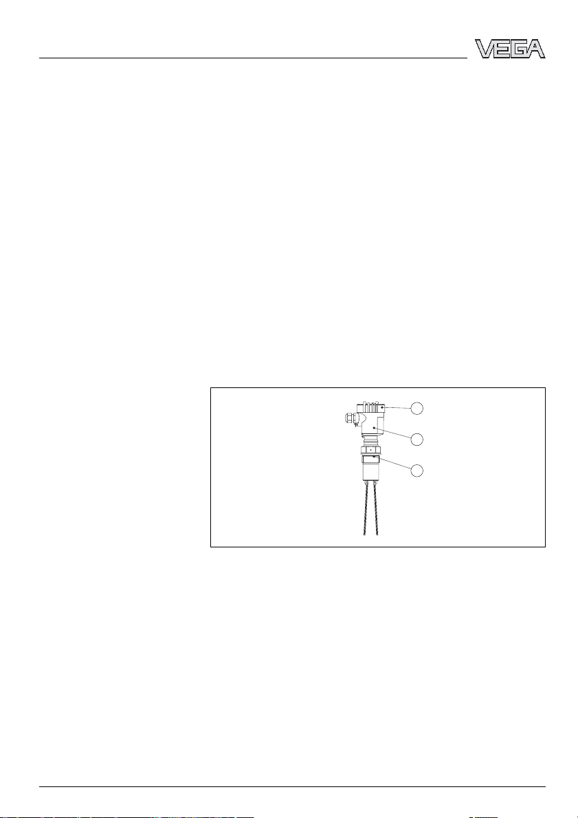
VEGAWAVE 61 is a compact instrument,i.e.it can be
operated without external evaluation system.The integrated
electronics evaluates the level signal and outputs a switching
signal.With this switching signal,a connected device can be
operated directly (e.g.a warning system,aPLC,a pump etc.).
The data for power supply are stated in chapter "Technical
data"in the "Supplement".
3.3Operation
With the factory setting,products with a density of >0.02 g/cm³
(0.0008 lbs/in³)can be measured.The instrument can also be
adapted to products with lower density >0.008 g/cm³
(0.0003 lbs/in³).
Functional principle
Supply
VEGAWAVE 61 --transistor (NPN/PNP)9
Product description
32248-EN-070117

On the electronics module you will find the following indicating
and adjustment elements:
lsignal lamp for indication of the switching condition (green/
red)
lpotentiometer for adaptation to the product density
lMode switch for selecting the switching condition (min./
max.)
3.4Storage and transport
Your instrument was protected by packaging during transport.
Its capacity to handle normal loads during transport is assured
by a test according to DIN EN 24180.
The packaging of standard instruments consists of environ-
ment-friendly,recyclable cardboard.In addition,the sensor is
provided with a protective cover of cardboard.For special
versions PE foam or PE foil is also used.Dispose of the
packaging material via specialised recycling companies.
lStorage and transport temperature see "Supplement -
Technical data -Ambient conditions"
lRelative humidity 20 …85 %
Packaging
Storage and transport tem-
perature
10 VEGAWAVE 61 --transistor (NPN/PNP)
Product description
32248-EN-070117

4Mounting
4.1General instructions
In general,VEGAWAVE 61 can be mounted in any position.
The instrument must be mounted in such a way that the
vibrating element is at the height of the requested switching
point.
Use the recommended cables (see chapter "Connecting to
power supply")and tighten the cable gland.
You can give your VEGAWAVE 61 additional protection
against moisture penetration by leading the connection cable
downward in front of the cable entry.Rain and condensation
water can thus drain off.This applies mainly to mounting
outdoors,in areas where moisture is expected (e.g.by
cleaning processes)or on cooled or heated vessels.
Fig.2:Measures against moisture penetration
Do not hold VEGAWAVE 61 on the vibrating element.
Especially with flange and tube versions,the sensor can be
damaged by the weight of the instrument.
Remove the protective cover just before mounting.
The process fitting must be sealed if there is gauge or low
pressure in the vessel.Before use,check if the seal material is
resistant against the measured product and the process
temperature.
The max.permissible pressure is stated in chapter "Technical
data"in the "Supplement"or on the type label of the sensor.
Switching point
Moisture
Transport
Pressure/Vacuum
VEGAWAVE 61 --transistor (NPN/PNP)11
Mounting
32248-EN-070117

The vibrating level switch is a measuring instrument and must
be treated accordingly.Bending the vibrating element will
destroy the instrument.
Warning:
The housing must not be used to screw the instrument in!
Applying tightening force on the housing can damage its
rotational mechanical parts.
To screw in,use the hexagon above the thread.
4.2Mounting instructions
The vibrating element should protrude into the vessel to avoid
buildup.For that reason,avoid using mounting bosses for
flanges and screwed fittings.This applies particularly to use
with adhesive products.
Mount the instrument in such a way that the tuning fork does
not protrude directly into the filling stream.
20°
a. b.
Fig.3:Horizontal mounting
aConvex mounting
bConcave mounting
If such an installation location should be necessary,mount a
suitable protective sheet above or in front of the vibrating
element,see illustration "a").
Handling
Socket
Filling opening
12 VEGAWAVE 61 --transistor (NPN/PNP)
Mounting
32248-EN-070117

In abrasive solids,mounting according to illustration "b"has
proven.Aspout forms in the concave protective sheet
preventing wear of the protective sheet.
To achieve a very precise switching point,you can install
VEGAWAVE 61 horizontally.However,if the switching point
can have a tolerance of a few centimeters,we recommend
mounting VEGAWAVE 61 approx.20°inclined to the vessel
bottom to avoid buildup.
20°
a. b.
Fig.4:Horizontal mounting
aProtective sheet
bConcave protective sheet for abrasive solids
IfVEGAWAVE 61 is mounted in the filling stream,measure-
ment errors can result.Mount VEGAWAVE 61 at a location in
the vessel where no disturbing influence from e.g.filling
openings,agitators,etc.can occur.
To minimise flow resistance caused by the tuning fork,
VEGAWAVE 61 should be mounted in such a way that the
surfaces of the blades are parallel to the product movement.
Horizontal mounting
Inflowing medium
Flows
VEGAWAVE 61 --transistor (NPN/PNP)13
Mounting
32248-EN-070117

1
2
Fig.5:Orientation of the tuning fork in case of flow
1Marking with screwed version
2Direction of flow
In case of horizontal mounting in adhesive products,the
surfaces of the tuning fork should be vertical in order to reduce
buildup on the blades.On the screwed version you will find a
marking on the hexagon.With this,you can check the position
of the tuning fork when screwing it in.When the hexagon
touches the seal,the thread can be still turned by approx.half
a turn.This is sufficient to reach the recommended installation
position.
With flange versions,the fork is directed to the flange holes.
1
Fig.6:Horizontal installation -marking
1Marking on top with screwed version
In applications such as grit chambers or settling basins for
coarse sediments,the vibrating element must be protected
against damage with a suitable baffle.
This baffle must be manufactured by you.
Adhesive products
Baffle protection against fall-
ing rocks
14 VEGAWAVE 61 --transistor (NPN/PNP)
Mounting
32248-EN-070117

> 125 mm
(4 59/64")
Fig.7:Baffle to protect against damages
VEGAWAVE 61 --transistor (NPN/PNP)15
Mounting
32248-EN-070117

5Connecting to voltage supply
5.1Preparing the connection
Generally note the following safety instructions:
lConnect only in the complete absence of line voltage
In hazardous areas you should take note of the appropriate
regulations,conformity and type approval certificates of the
sensors and power supply units.
Connect the power supply according to the following diagrams.
Take note of the general installation regulations.As a rule,
connect VEGAWAVE 61 to vessel ground (PA), or in case of
plastic vessels,to the next ground potential.On the side of the
instrument housing there is a ground terminal between the
cable entries.This connection serves to drain offelectrostatic
charges.InEx applications,the installation regulations for
hazardous areas must be given priority.
The data for power supply are stated in chapter "Technical
data"in the "Supplement".
VEGAWAVE 61 is connected with standard cable with round
cross-section.An outer cable diameter of 5…9mm
(0.2…0.35 in)ensures the seal effect of the cable entry.
If cable with a different diameter or wire cross section is used,
exchange the seal or use an appropriate cable connection.
In hazardous areas,only use approved cable connections for
VEGAWAVE 61.
Take note of the corresponding installation regulations for Ex
applications.
5.2Connection procedure
With Ex instruments,the housing cover may only be opened if
there is no explosive atmosphere present.
Proceed as follows:
1Unscrew the housing cover
2Loosen compression nut of the cable entry
Note safety instructions
Take note of safety
instructions for Ex
applications
Select power supply
Selecting connection cable
Select connection
cable for Ex applica-
tions
16 VEGAWAVE 61 --transistor (NPN/PNP)
Connecting to voltage supply
32248-EN-070117

3Remove approx.10 cm (4in)of the cable mantle,strip
approx.1cm (0.4in)insulation from the ends of the
individual wires
4Insert the cable into the sensor through the cable entry
5Lift the opening levers of the terminals with a screwdriver
(see following illustration)
6Insert the wire ends into the open terminals according to
the wiring plan
7Press down the opening levers of the terminals,you will
hear the terminal spring closing
8Check the hold of the wires in the terminals by lightly
pulling on them
9Tighten the compression nut of the cable entry.The seal
ring must completely encircle the cable
10 If necessary,carry out a fresh adjustment
11 Screw the housing cover back on
The electrical connection is finished.
Fig.8:Connection steps 5and 6
5.3Wiring plan,single chamber housing
The following illustrations apply to the non-Ex as well as to the
EEx d version.
VEGAWAVE 61 --transistor (NPN/PNP)17
Connecting to voltage supply
32248-EN-070117

1
4
44
2 3
Fig.9:Material versions,single chamber housing
1Plastic (not with EExd)
2Aluminium
3Stainless steel (not with EExd)
4Filter element for pressure compensation or blind stopper with version IP 66/
IP 68,1bar (not with EExd)
3
4
5
1
2
Fig.10:Electronics and connection compartment
1Potentiometer for switching point adaptation
2DIL switch for mode adjustment
3Ground terminal
4Screwed terminals
5Control lamp
We recommend connecting VEGAWAVE 61 in such a way that
the switching circuit is open when there is a level signal,line
break or failure (safe condition).
The instrument is used to control relays,contactors,magnet
valves,warning lights,horns as well as PLC inputs.
Housing overview
Electronics and connection
compartment
Wiring plan
18 VEGAWAVE 61 --transistor (NPN/PNP)
Connecting to voltage supply
32248-EN-070117

1
Fig.11:Wiring plan
+ -
+-
Fig.12:NPN action
+-
+ -
Fig.13:PNP action
VEGAWAVE 61 --transistor (NPN/PNP)19
Connecting to voltage supply
32248-EN-070117

5.4Wiring plan,version IP 66/IP 68,1bar
+
-
1
2
Fig.14:Wire assignment,connection cable
1brown (+)and blue (-) to power supply or to the processing system
2Screen
Wire assignment,connection
cable
20 VEGAWAVE 61 --transistor (NPN/PNP)
Connecting to voltage supply
32248-EN-070117
Other manuals for VEGAWAVE 61
4
Table of contents
Other Vega Accessories manuals

Vega
Vega VEGAPULS 66 Profibus PA User manual

Vega
Vega VEGAPULS 66 User manual

Vega
Vega VEGAPULS 66 User manual

Vega
Vega vegaflex 83 User manual

Vega
Vega VEGACAL 65 User manual

Vega
Vega WEIGHTRAC 31 User manual

Vega
Vega VEGAPULS 63 User manual

Vega
Vega VEGAPULS 62 User manual

Vega
Vega VEGAPULS 62 User manual

Vega
Vega VEGABAR 81 User manual

Vega
Vega VEGAPULS 69 User manual

Vega
Vega VEGAPULS 68 User manual

Vega
Vega FIBERTRAC 31 User manual

Vega
Vega VEGAPULS C 21 User manual

Vega
Vega VEGAFLEX 81 User manual

Vega
Vega VEGAPULS 62 User manual

Vega
Vega VEGAFLEX 81 User manual

Vega
Vega VEGAPULS WL 61 User manual

Vega
Vega VEGAFLEX 82 User manual

Vega
Vega VEGAPULS C 22 User manual