2
Contents
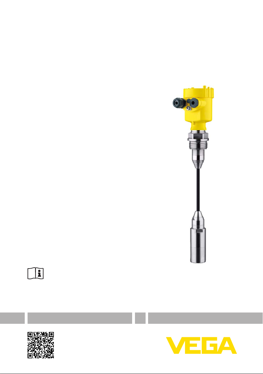
VEGABAR 86 • Secondary Device for electronic dierential pressure
48048-EN-220817
Contents
1 About this document ............................................................................................................... 4
1.1 Function ........................................................................................................................... 4
1.2 Target group..................................................................................................................... 4
1.3 Symbols used................................................................................................................... 4
2 For your safety ......................................................................................................................... 5
2.1 Authorised personnel ....................................................................................................... 5
2.2 Appropriate use................................................................................................................ 5
2.3 Warning about incorrect use............................................................................................. 5
2.4 General safety instructions............................................................................................... 5
2.5 Conformity........................................................................................................................ 5
2.6 SIL qualication according to IEC 61508.......................................................................... 6
2.7 NAMUR recommendations .............................................................................................. 6
2.8 Installation and operation in the USA and Canada ........................................................... 6
2.9 Environmental instructions ............................................................................................... 6
3 Product description ................................................................................................................. 7
3.1 Conguration.................................................................................................................... 7
3.2 Principle of operation........................................................................................................ 8
3.3 Packaging, transport and storage................................................................................... 11
3.4 Accessories.................................................................................................................... 12
4 Mounting................................................................................................................................. 13
4.1 General instructions ....................................................................................................... 13
4.2 Ventilation and pressure compensation.......................................................................... 15
4.3 Combination Primary - Secondary ................................................................................. 17
4.4 Dierential pressure measurement ................................................................................ 18
4.5 Interface measurement .................................................................................................. 18
4.6 Density measurement .................................................................................................... 19
4.7 Density-compensated level measurement ..................................................................... 20
4.8 External housing ............................................................................................................ 22
5 Connecting to power supply................................................................................................. 23
5.1 Preparing the connection ............................................................................................... 23
5.2 Connecting..................................................................................................................... 24
5.3 Single chamber housing................................................................................................. 25
5.4 External housing with version IP68 (25 bar) ................................................................... 26
5.5 Connection example ...................................................................................................... 28
6 Functional safety (SIL) .......................................................................................................... 29
6.1 Objective........................................................................................................................ 29
6.2 SIL qualication.............................................................................................................. 29
6.3 Application area ............................................................................................................. 29
6.4 Safety concept of the parameterization .......................................................................... 30
7 Set up with the display and adjustment module ................................................................ 32
7.1 Parameter adjustment .................................................................................................... 32
7.2 Menu overview ............................................................................................................... 45
8 Diagnosis, asset management and service ........................................................................ 48
8.1 Maintenance .................................................................................................................. 48
8.2 Rectify faults................................................................................................................... 48