Verano V160 Florence User manual

Drop-arm awning
V160 Florence
Installation manual


V160-13227648-180830EN(2)
Installation manual drop-arm awning V160 Florence
Content
1. Drop-arm awning *
2. Control
a. Manual control: crank handle
b. Manual control: manual control mono inside ( winding machine inside + crank handle)
c. Electrical control: switch + plug
d. Remote control: remote control + plug
* Depicted awning has manual control
1
Necessary tools
• Drilling machine
• Masonry drill
• Crosshead screwdriver
• Socket wrench 10/13/17
• Allen key set
• Rattle with extension piece, cap 10/17 mm
• Tapeline
• Level
• Pencil
In case of electrical control:
• Shears
• Flathead screwdriver
2
1

Subject to misprints, errors and technical modifications.
Important before installation
2
Be careful for damages
Don’t use a knife or any other sharp object when opening the packing. This may cause damage to the content
of the package.
Put the content of the package on a so surface. Be careful when drilling, falling drill cuttings can cause damages.
Check if the window frame or façade is at and smooth.
General warning
Installing the Verano® product yourself is at your own risk. Only use this instruction as a tool and for the installation
of this specic Verano® product.
If you cannot install the product yourself, you can always opt for professional installation. The installation team
of Verano® is pleased to help you.
Specications V160 Florence
20
40
20
26
110
60 24
6
10
110
126
12
4
126
wall support awning cross section
Installation
Width (W)
minimal 2000 mm maximal 8000 mm
Measurements in mm

V160-13227648-180830EN(2)
Installation manual drop-arm awning V160 Florence
3
1.1 Marking the holes for the wall supports
The wall supports need to be installed 10 cm to 15 cm from the ends (g 1.1).
Optional remaining wall supports need to be divided equally between the two outer wall supports.
Mark the drill holes of the wall supports to the wall (A). They need to be aligned level, both horizontal and vertical.
See gure 1.2. Make sure that both the installation holes for the wall supports are in the middle of the stone.
See gure 1.3. If necessary, use an align-cord.
g. 1.2 Placement of the wall supports
g. 1.1 Marking the holes for the wall supports
A
muursteun
A
muursteun
X
1. Installation of the wall supports
X = Width of the awning
Y = Installation height (from the ground)
A = Wall supports
X
Y
AA
X = Width of the awning
wall support wall support

Subject to misprints, errors and technical modifications.
4
g. 1.3 Installation of the wall support
1.2 Drilling the holes
Drill the installation holes. Use matching, high quality plugs
and bolts (standard A2 or for a sea climate A4). Install the
awning to the wall and xate the bolts. See gure 1.3.
1.3 Drilling the operating hole (when operating indoors)
1. Carefully mark out the grommet where the cord or axle should be for operation. Electric: the hole for the cord must be
at the exact same height as the place where the cord comes out! Mono inside: the hole for the axle must be at the exact
same height as the spot where the axle comes out of the cover!
See gure 1.4 (The axle can possibly pass under a (vertical) angle through the wall. This angle should be
specied in advance while ordering the screen, see gure 1.5)
2. Make sure that there are no pipes and the like in the wall when drilling!! Always use a slat on the inside of the house,
so that the stucco doesn’t get damaged.
Electrical: Grommet for electrical cord: 10 mm.
Mono inside: grommet for axle: ± 15 mm.
g. 1.4 Standard installation manual control mono inside g. 1.5 Knee joint with movable axle
V160-13227648-180830EN(2)
Installation manual drop-arm awning V160 Florence
5
2.1 Installation of the awning with manual control (outside)
Hang the awning in the wall supports. See gure 2.1 and 2.2. Proceed with step 2.3 “Securing the awning”.
2. Installation of the awning
g. 2.2 Detail wall support
g. 2.1 Hang the awning (outside control)
1.6 Extra wall supports with a weak wall
If there are less than 5 stones above the installation location, an extra wall support is needed. This extra wall
support divides the power over a bigger wall surface, this way the wall can carry more weight. See gure 1.6.
extra
g. 1.6 Application of extra wall supports
g. 1.5 Knee joint with movable axle

Subject to misprints, errors and technical modifications.
2.2 Installation of the awning with inside control
1. Hang the awning in the wall supports. See gure 2.3 or electrical control or 2.4 for manual control mono inside.
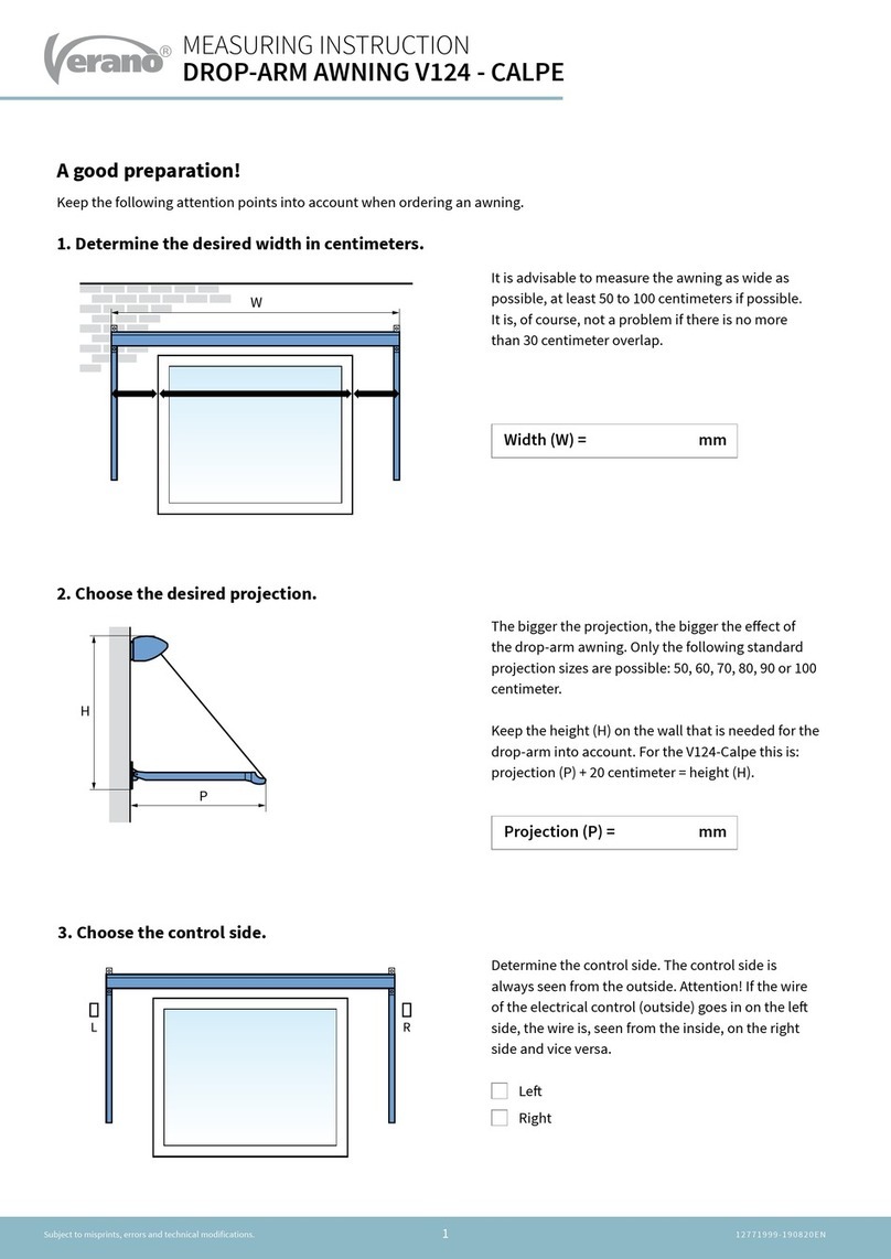
2. Cable: lead the electrical cable inside through the drill lead-through hole.
mono commando
snoer mono commando
snoer
g. 2.3 Hanging a motorized awning g. 2.4 Hanging an awning with manual control mono inside
Cable
6

V160-13227648-180830EN(2)
Installation manual drop-arm awning V160 Florence
2.3 Securing of the awning
1. Secure the wall supports using the included bolts. The bolts need to be applied manually. If this is not possible,
the wall supports are nog aligned well! Attention! The awning may not be opened before the securing bolts
are in place!
g. 2.6 Applying the securing bolts
7

Subject to misprints, errors and technical modifications.
3.1 Marking the holes for the drop-arms
Mark the drop-arms following the drawing below. The drop-arms need to be placed in one line. If the positions
of the drop-arms are not levelled, the awning will not function well. The pictured sizes are the minimal sizes that
the drop-arm needs to fall inside the drop-arm awning.
3.2 Drilling the holes
Drill the installation holes. We advise to use a masonry drill if the wall is made of stone or concrete. Use matching,
high quality plugs and bolts (standard A2 or for a sea climate A4). Install the drop-arm to the wall by rst xing it on
the bottom side (g 3.2).
Remove the tape from the arm (g 3.3). Attention! The arm is under tension and will unfold immediately!
Fixate the top side(3.4).
3. Installation of the drop-arms
g. 3.1 Measuring the drop-arms
g. 3.2 Fixate the bottom of the drop-arm g. 3.3 Remove the tape g. 3.4 Fixate the top of the drop-arm
Control side
Manual outside: 48 mm
Manual inside: 13 mm
Electrical: 13 mm
Projection + 70 mm =
Bottom arm guide
13 mm
8

V160-13227648-180830EN(2)
Installation manual drop-arm awning V160 Florence
3.3 Setting the sheets to the arms
Slide the sheets in the ends of the arms. Make sure that the sheets are faced downwards (g. 3.5).
Fixate the sheets with the included screws (g. 3.6)
3.4 Fixing the arms to the front bar
Turn the drop-arm up (g 3.7) Attention! The arm is under pressure.
Screw the drop-arm to the xing plate in the front bar (g. 3.8).
Repeat these steps for all arms.
g. 3.5 Sheet in the arms
g. 3.7 Folding back the drop-arm
g. 3.6 Fixating of the sheets
g. 3.8 Fixating the drop-arm
9

Subject to misprints, errors and technical modifications.
10
1. Determine the length of the square axle and cut
it to size.
2. Slide the axle through the wall into the windings
of the drop-arm awning.
3. Position the knee joint and mark the drill holes
on the frame or wall. Ensure that the axle can
move freely through the drill hole!
4. Drill the holes.
5. Insert the plugs (optional) and t the knee joint
with two countersunk screws.
The manually operated drop-arm awning is ready
for use and can now be freely operated from the
inside using the crank handle.
4. Installation instructions manual mono operation (inside)

V160-13227648-180830EN(2)
Installation manual drop-arm awning V160 Florence
11
1. Determine the position of the
switch and mark two holes on the
inside of the wall.
2. Drill the holes with a 6 mm drill.
3. Open the switch using a athead
screwdriver.
4. Place the plugs and install the
switch using two recessed screws.
Make sure that the power is
switched o and without voltage!
Ø6
230 V
5. Installation of electrical control (inside)
Optioneel
230 V
Optional

Subject to misprints, errors and technical modifications.
12
5. Connect the 4-wired cable of the motor and the 3-wired cable and plug following the scheme below.
If necessary, ask an installer for advise.
yellow/green
blue
brown
yellow/green
blue black
brown
brown
yellow/green
blue
brown
yellow/green
blue
black
brown
brown
yellow/green
blue
brown
yellow/green
blue black
brown
brown
yellow/green
blue
brown
yellow/green
blue
black
brown
brown
Motor le (seen from the outside) Motor right (seen from the outside)
Optioneel
230 V
6. Install the switch.
When a wireless remote control is
used, the 3-wired cable can be
connected directly to the socket.
7. Put the plug in the socket and turn
the power on.
The drop-arm awning is now ready.
* See the included SOMFY instruction for the setting of the remote control.
Optional *

V160-13227648-180830EN(2)
Installation manual drop-arm awning V160 Florence
13
Make sure that the front bar is located at an equal distance from the cap over the whole width (g. 6.1). Set the front bar
by loosening the bolts of the drop-arm in one turn (g 6.2). Aer that, the drop-arm can slide up and down (g. 6.3). If the
front bar is set well, you can x the bolts of the drop-arm (g 6.4).
6. Setting of the front bar
g. 6.1 Examples of settings
g. 6.2 Loosening the bolts g. 6.3 Setting of the front bar g. 6.4 Fixing of the bolts
1x
1x

Subject to misprints, errors and technical modifications.
14
A high quality cloth is integrated into your chosen
screen. In view of optimal quality we have chosen a high
technology production process in which every step of
the production is strictly selected. By way of automation,
permanent checks, laboratory tests and finely detailed
after-care, nothing is left to chance. This allows us to
guarantee the resistance as well as the strength and
durability of the colours of your screen for many years to
come.
Starting with a completely pigmented poly-acryl material,
which gives it its exceptional quality, our screens have
the advantage of total monitoring during the production
process. In spite of all this there may be small irregularities
in your screen that are difficult to detect and impossible
to avoid. They are inherent in all technical materials but
do not reduce the technical presentation and durability
of your screen.
Waffling, chalk stripes, small pleats next to the seam or
in the middle of the screen or nap can appear. The retailer
cannot be held responsible for these irregularities.
Cable motor: if broken off, cannot be guaranteed.
User information
These small irregularities have no effect whatsoever on the quality of the screen and do not constitute the screen being
replaced. However do inform us if you notice any irregularities in colour fastness, decay or resistance, in fact in any of the basic
characteristics of our 2-year guarantee.
Wave forming
Next to the seams, caused by the
unavoidable tension difference in
rolling up.
Fold stripes/ chalk stripes
A fold caused during the
manufacture, can show a darker
stripe by light reflection. This is
mostly noticeable in lighter
coloured blinds.
Wave forming or wrinkle forming
All technical materials can display
these symptoms in the middle of
a canvas. They are especially
noticeable with backlight through
the difference in light reflection.

V160-13227648-180830EN(2)
Installation manual drop-arm awning V160 Florence
15
Notes

www.verano.eu
This manual suits for next models
1
Table of contents
Other Verano Accessories manuals

Verano
Verano Mallorca Special V150 User manual

Verano
Verano V612 HAMAR User manual

Verano
Verano DROP-ARM AWNING V120 NAPOLI User manual

Verano
Verano Odense V640 User manual

Verano
Verano V225 Porto User manual

Verano
Verano V124 - CALPE User manual

Verano
Verano V285-RECIFE User manual

Verano
Verano V124 - CALPE User manual

Verano
Verano V880 RAPOLLO User manual

Verano
Verano VERANDA V905 - ISEO User manual