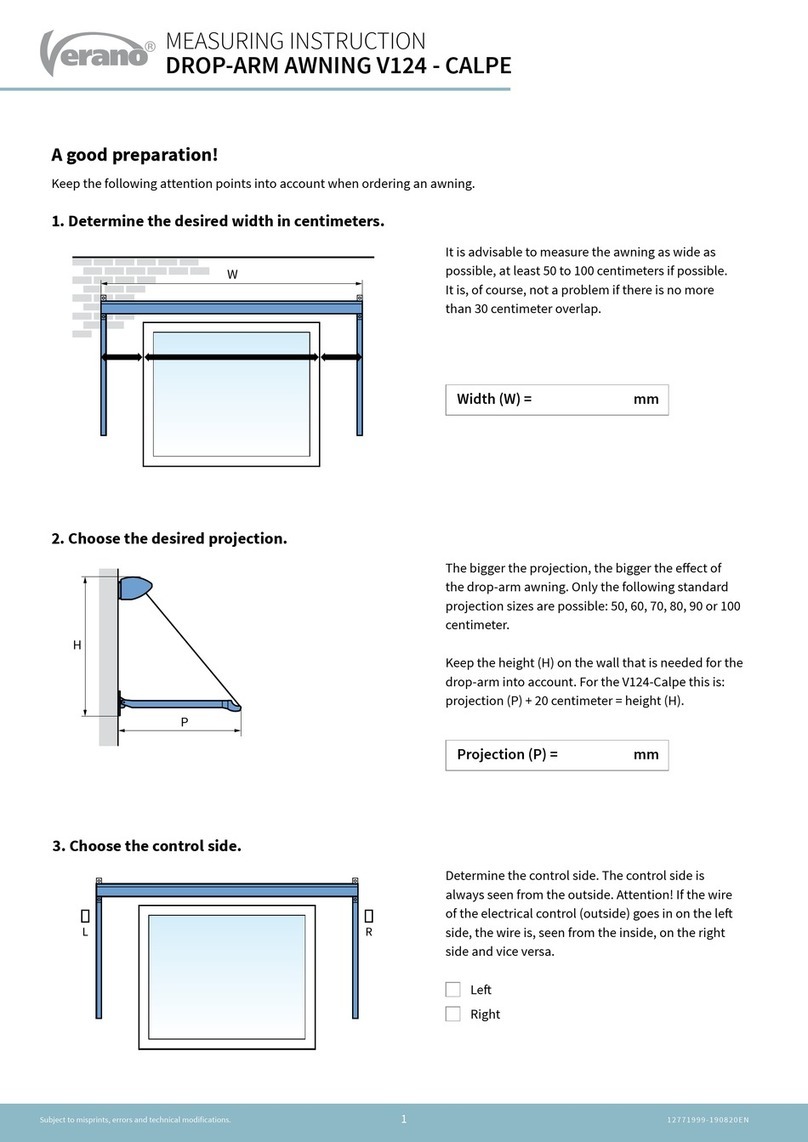
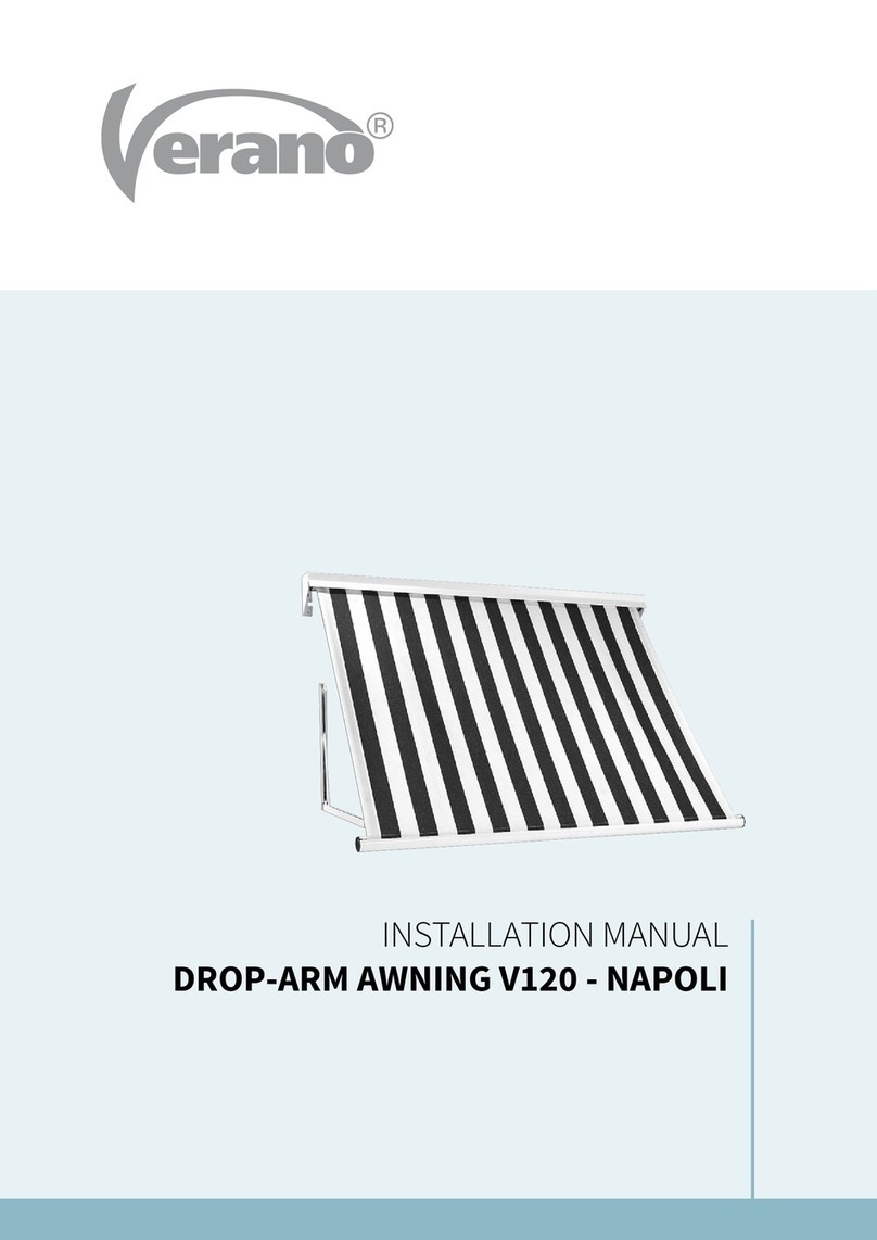
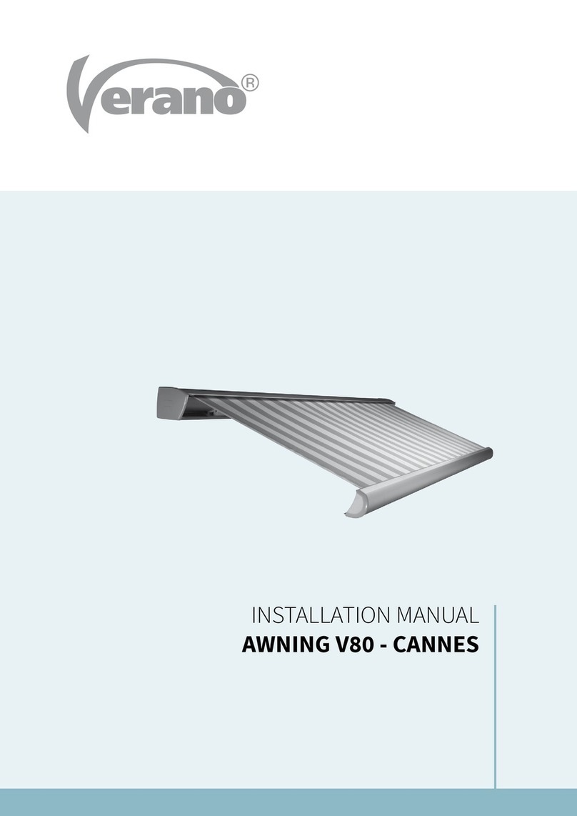
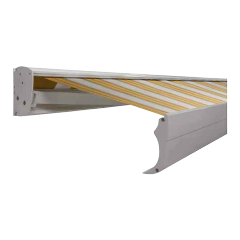
Verano V124 - CALPE User manual

INSTALLATION MANUAL
DROP-ARM AWNING V124 - CALPE

INSTALLATION MANUAL DROP-ARM AWNING V124 - CALPE
12771999-19830EN
1
Subject to misprints, errors and technical modifications.
Content
1. Drop-arm awning *
2. Wall supports
3. Control
a. Manual control: crank handle
b. Electrical control: switch and plug
c. Remote control: remote control and plug
* The pictured awning is provided with manual control.
Necessary tools
• Drilling machine
• Support drill
• Crosshead screwdriver
• Socket wrench 10/13/17
• Keyset
• Ratchet with extension, cap 10/17 mm
• Tapeline
• Plumb rule
• Pencil
In case of electrical control:
• Nippers
• Flathead screwdriver
2
3
1
2

INSTALLATION MANUAL DROP-ARM AWNING V124 - CALPE
12771999-19830EN
2
Subject to misprints, errors and technical modifications.
Important before the installation
Be careful for damages
Don’t use a knife or any other sharp object when opening the packing. This may cause damage to the content
of the package. Put the content of the package on a so surface. Be careful when drilling, falling drill cuttings
can cause damages.
Check if the window frame or façade is at and smooth.
General warning
Installation of the Verano® product yourself is at your own risk. Only use this instruction as a tool and for the installation of
this specic Verano® product. If you cannot install the product yourself, you can always opt for professional installation.
The installation team of Verano® is pleased to help you.
Specications V124 - Calpe
136
91,23
9,90
70
2,38
78
29
2833
= =
19
7
Wall support
Section awning
Installation
Width (W)
Minimum 600 mm Maximum 3000 mm
Sizes in mm

INSTALLATION MANUAL DROP-ARM AWNING V124 - CALPE
12771999-19830EN
3
Subject to misprints, errors and technical modifications.
1.1 Marking the holes
The wall supports need to be installed 10 to 15 centimeter from the ends (gure 1.1).
Optional remaining wall supports need to divided equally between the two outer wall supports.
Mark the holes for the wall supports (A). These holes need to be aligned level, horizontal and vertical. See gure 1.2.
Make sure that there are at least two holes in the middle of a stone.
View gure 1.3. If necessary, use an alignment string.
Figure 1.2 Installation of the wall supports.
Figure 1.1 Marking the wall supports
A
muursteun
A
muursteun
X
1. Installation of the wall supports
X = width of the awning.
Y = installation height (from the ground).
A = wall supports.
X
Y
AA
X = Width of the awning
A
Wall support
A
Wall support

INSTALLATION MANUAL DROP-ARM AWNING V124 - CALPE
12771999-19830EN
4
Subject to misprints, errors and technical modifications.
1.3 Drilling the hole for control
1. Precisely mark the hole where the cable of the control comes in.
- Cable: the hole needs to be marked at exactly the same height as the place where the cable leaves the box.
- Tape: the hole needs to be at least 50 millimeter below the box, exactly beneath the place where the tape
leaves the box.
2. Drill the hole for the wall throughput.
Always check the wall for piping or other obstacles! Use a board on the inside of the house to prevent damage
to the stuccowork.
- Wall throughput for tape: 20 millimeter (drill 10 millimeter, than 20 millimeter).
- Wall throughput for cable: 10 millimeter.
Figure 1.3 Installation of the wall support.
1.2 Drilling the holes
Drill the installation holes. Use matching plugs and bolts
of high quality. Install the wall supports (A) and tighten the
bolts. See gure 1.3.
1.4 Additional wall support (weak wall)
When there are fewer than ve rows of stones above the installation location, an additional wall support needs to be used.
This additional wall support divides the forces over a bigger wall surface, the wall can than bear more weight.
See gure 1.4.
extra
Figure 1.4. Applying additional wall supports.
INSTALLATION MANUAL DROP-ARM AWNING V124 - CALPE
12771999-19830EN
5
Subject to misprints, errors and technical modifications.
2.1 Placing the awning (manual control outside)
Hang the awning in the wall supports. See gure 2.1 and 2.2. Proceed with step 2.3 “Securing the awning”.
2. Installation of the awning
Figure 2.2 Detail wall support.
Figure 2.1 Hanging the awning (control outside).

INSTALLATION MANUAL DROP-ARM AWNING V124 - CALPE
12771999-19830EN
6
Subject to misprints, errors and technical modifications.
2.2 Placing the awning (control inside)
1. Hang the awning in the wall supports. See gure 2.3 for electrical control or 2.4 for tape control.
2. Cable: slide the electrical cable inside through the drilled throughput.
Tape: install the tape guide with the opening over the throughput and the pulley on top. Slide the tape inside through
the tape guide and the drilled throughput.
1
band
2
snoer
1
band
2
snoer
Figure 2.5 Detail wall support
Figure 2.3 Hanging the awning (electrical control) Figure 2.4 Hanging the awning (tape control inside)
Cable Tape

INSTALLATION MANUAL DROP-ARM AWNING V124 - CALPE
12771999-19830EN
7
Subject to misprints, errors and technical modifications.
2.3 Securing the awning
1. Lock the wall supports using the included locking bolts. The locking bolts need to be placed manually.
If this fails, the wall supports are not aligned correctly!
2. Fixate the locking bolts by turning them a quarter turn (anticlockwise if you are standing beneath the awning).
Fixate the locking bolt with the included nut.
Attention! The awning may never be opened before the locking bolts are placed!
Figure 2.3 Placing the locking bolts.

INSTALLATION MANUAL DROP-ARM AWNING V124 - CALPE
12771999-19830EN
8
Subject to misprints, errors and technical modifications.
3.1 Drilling the holes for the lower arm support
Drill the holes following the drawing below. The pictured sizes are the minimal sizes for the drilled hole to be from the side
of the awning.
3.2 Fixation of the drop-arm support
Put the plug with the bolt and ring in the drilled hole (gure 3.2). Turn the bolt until a space of 8 mm remains between the
wall and the bolt (g 3.3). Slide arm support with the lower hole over the bolt (gure 3.4). Turn the drop-arm up to xate
the bolt (gure 3.5). ATTENTION! The spring in the arm is stretched! Turn the bolt until it is almost xed.
Attention! Some clearance is necessary for the adjustment of the front bar.
3. Installation drop-arms
± 8 mm
± 8 mm
Projection + 9 mm
= Heart of the drilled hole
Control side
Manual outside: 57 mm
Manual inside: 22 mm
Electrical: 22 mm
22 mm
± 8 mm
Figure 3.1 Measuring the holes
Figure 3.2 Plug, bolt and ring in the drilled hole.
Figure 3.4 Slide the drop-arm over the bolt.
Figure 3.3 Turning the bolt.
Figure 3.5 Turn the drop-arm and the xate the bolt.

INSTALLATION MANUAL DROP-ARM AWNING V124 - CALPE
12771999-19830EN
9
Subject to misprints, errors and technical modifications.
3.3 Fixating the arms to the front bar
Turn the drop-arm up and stick it in the front bar. Lock the drop-arm by turning the screw on the front side (gure 3.6).
Figure 3.6 Placing the locking bolts.
3.4 Adjusting the front bar
Make sure that the front bar is 15 mm from the top cap over the whole width (gure 3.7). Slide the drop-arm support
up or down a little to adjust the front bar (gure 3.9). If the front bar is adjusted correctly, turn the xation bolt of the
drop-arm support (gure 3.10).
15
Figure 3.7 Distance between the front bar en top cap Figure 3.8 Adjustment examples
Figure 3.9 Adjustment of the drop-arm support Figure 3.10 Fixation of the bolt

INSTALLATION MANUAL DROP-ARM AWNING V124 - CALPE
12771999-19830EN
10
Subject to misprints, errors and technical modifications.
5mm
50mm
1. Determine the position of the strap guide
(50 mm to 100 mm below the boxing of the
drop-arm awning) and mark both holes on the
window frame or the wall. Make sure that the
strap and strap guide are aligned!
2. Drill the holes.
3. Place the plugs and install the strap guide with
two countersunk screws.
4. Put the pull strap through the strap guide.
Make sure that the pull strap is not twisted.
5. Determine the position of the strap coiler and
mark both holes on the window frame or the
wall. Make sure that the strap and the coiler
are aligned!
6. Drill the holes.
7. Place the plugs and install the strap coiler with
two countersunk screws.
8. Fold the end of the pull strap double and cut
a little hole.
4. Instruction for placing the strap coiler (outside)

INSTALLATION MANUAL DROP-ARM AWNING V124 - CALPE
12771999-19830EN
11
Subject to misprints, errors and technical modifications.
11. The manual controlled drop-arm awning is now ready to use and can be controlled trouble free from the outside.
9. Put the end of the pull strap through the strap
coiler and place the hole over the ap to make
sure that it is xated well.
Attention! You may never prematurely shorten the
strap! You need the length of the strap when you
open the drop-arm awning.
10. Break the plastic hook to bring tension to the
strap coiler. The full length of the strap rolls now
automatically on the strap coiler.
1
2
2

INSTALLATION MANUAL DROP-ARM AWNING V124 - CALPE
12771999-19830EN
12
Subject to misprints, errors and technical modifications.
1. Put the pull strap through the guide wheel
on the inside. Make sure that the pull strap
is not twisted.
2. Place the guide wheel in the control hole.
3. Determine the position of the strap coiler and
mark both holes on the window frame or the
wall. Make sure that the strap and the coiler
are aligned!
4. Drill the holes.
5. Place the plugs and install the strap coiler with
two countersunk screws.
6. Fold the end of the pull strap double and cut
a little hole.
5mm
50mm
5. Instruction placing the strap coiler (inside)

INSTALLATION MANUAL DROP-ARM AWNING V124 - CALPE
12771999-19830EN
13
Subject to misprints, errors and technical modifications.
1
2
1
2
2
10. The manual controlled drop-arm awning is now ready to use and can be controlled trouble free from the inside.
7. Put the end of the pull strap through the strap
coiler and place the hole over the ap to make
sure that it is xated well.
Attention! You may never prematurely shorten the
strap! You need the length of the strap when you
open the drop-arm awning.
8. Break the plastic hook to bring tension to the
strap coiler. The full length of the strap rolls now
automatically on the strap coiler.
9. Place the cover on the strap coiler.

INSTALLATION MANUAL DROP-ARM AWNING V124 - CALPE
12771999-19830EN
14
Subject to misprints, errors and technical modifications.
1. Determine the position of the
switch on the inside and mark both
holes on the wall.
2. Drill the holes with a 6 mm drill.
3. Open the switch using a athead
screwdriver.
4. Place the plugs and install the
switch with two countersunk
screws. Make sure that the group-
power is o and tension-free!
Ø6
230 V
6. Instruction for placing the electrical control (inside)
Optioneel
230 V
Optional

INSTALLATION MANUAL DROP-ARM AWNING V124 - CALPE
12771999-19830EN
15
Subject to misprints, errors and technical modifications.
5. Connect the 4-wired cable of the motor and the 3-wired cable and plug following the scheme below.
Turn to an installer if necessary.
Motor le (seen from the outside) Motor right (seen from the outside)
Optioneel
230 V
6. Install the switch.
In case of a wireless remote control,
the 3-wired cable can be installed
directly to the socket.
7. Put the plug in the power point and
turn the power on.
The drop-arm awning is now ready
to use.
* See the included Somfy instruction for the setting of the remote control.
*
Optional
geel/groen
blauw
bruin
geel/groen
blauw zwart
bruin
bruin
geel/groen
blauw
bruin
geel/groen
blauw
zwart
bruin
bruin
geel/groen
blauw
bruin
geel/groen
blauw zwart
bruin
bruin
geel/groen
blauw
bruin
geel/groen
blauw
zwart
bruin
bruin
brown
brown
brown
brown
brown
brown
black
black
blue
blue
blue
blue
yellow/green
yellow/green
yellow/green
yellow/green

INSTALLATION MANUAL DROP-ARM AWNING V124 - CALPE
12771999-19830EN
16
Subject to misprints, errors and technical modifications.
Figure 7.1 Drill the xation hole. Figure 7.2 Fixate the drop-arm bracket.
Open the awning to make sure that you have access to the upper hole of the drop-arm support. Drill the xation hole
through the free hole in the bracket. Attention! Make sure that drill cuttings do not fall in the hinge of the drop-arm.
The cuttings can obstruct the functioning of the hinge. Fixate the drop-arm bracket.
7. Fixation of the drop-arm support

INSTALLATION MANUAL DROP-ARM AWNING V124 - CALPE
12771999-19830EN
17
Subject to misprints, errors and technical modifications.
8.1 Place the valance
To place the valance, follow the steps below. See gure 8.1.
1. Remove the cap from the front bar on one side. The fabric tendon is locket in the front bar.
2. Slide the fabric tendon in the valance on the opened fabric side.
3. Slide the valance carefully in the gap. Make sure that you guide the valance accurately to prevent ripping!
4. Replace the cap on the front bar.
8. Valance
1
234
Figure 8.1 Placing the valance.

INSTALLATION MANUAL DROP-ARM AWNING V124 - CALPE
12771999-19830EN
18
Subject to misprints, errors and technical modifications.
User information
A high quality cloth is integrated into your chosen screen. In view of optimal quality we have chosen a high technology
production process in which every step of the production is strictly selected. By way of automation, permanent checks,
laboratory tests and nely detailed aer-care, nothing is le to chance. This allows us to guarantee the resistance as well as
the strength and durability of the colours of your screen for many years to come.
Starting with a completely pigmented poly-acryl material, which gives it its exceptional quality, our screens have the advantage
of total monitoring during the production process. In spite of all this there may be small irregularities in your screen that
are diicult to detect and impossible to avoid. They are inherent in all technical materials butdo not reduce the technical
presentation and durability of your screen.
Waling, chalk stripes, small pleats next to the seam or in the middle of the screen or nap can appear. The retailer cannot be
held responsible for these irregularities.
Cable motor: if broken o, cannot be guaranteed.
These small irregularities have no eect whatsoever on the quality of the screen and do not constitute the screen being
replaced. However do inform us if you notice any irregularities in colour fastness, decay or resistance, in fact in any of the
basic characteristics of our 2-year guarantee.
Wave forming or wrinkle forming
All technical materials can display
these symptoms in the middle of
a canvas. They are especially
noticeable with backlight through
the dierence in light reection.
Wave forming
Next to the seams, caused by the
unavoidable tension dierence in
rolling up.
Fold stripes/ chalk stripes
A fold caused during the
manufacture, can show a darker
stripe by light reection. This is
mostly noticeable in lighter
coloured blinds.
Other manuals for V124 - CALPE
1
Table of contents
Other Verano Accessories manuals

Verano
Verano V285-RECIFE User manual

Verano
Verano V160 Florence User manual

Verano
Verano Mallorca Special V150 User manual

Verano
Verano Odense V640 User manual

Verano
Verano V480 Cannes User manual

Verano
Verano V612 HAMAR User manual

Verano
Verano V610 Oslo User manual

Verano
Verano V360 User manual

Verano
Verano V460 SANTANDER User manual

Verano
Verano V805 CORTONA User manual
Popular Accessories manuals by other brands

MadJax
MadJax 01-065 Nstallation instructions

ROSE DISPLAYS
ROSE DISPLAYS RAN-BAS-CC SPIDER ANCHOR-GENERIC instruction sheet

Mi-Si
Mi-Si Mi-Si Acoustic Trio Uke owner's manual

Malmbergs
Malmbergs Sense manual

In-Circuit
In-Circuit ICflyAHRSII Installation guide & user manual

GE
GE 19234 installation instructions