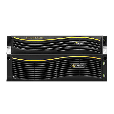
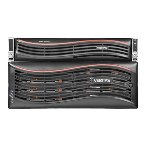
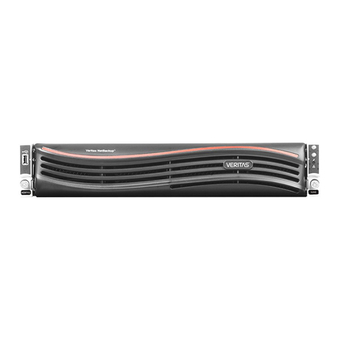
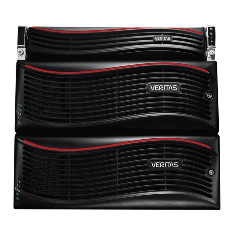
VERITAS NetBackup 523 Operating and maintenance instructions

Veritas NetBackup™ 5230
Appliance Hardware
Installation Guide
Release 2.7.3

Veritas NetBackup™ 5230 Appliance Hardware
Installation Guide
Document version: 2.7.3
Legal Notice
Copyright © 2016 Veritas Technologies LLC. All rights reserved.
Veritas, the Veritas Logo, and NetBackup are trademarks or registered trademarks of Veritas
Technologies LLC or its affiliates in the U.S. and other countries. Other names may be
trademarks of their respective owners.
This product may contain third party software for which Veritas is required to provide attribution
to the third party (“Third Party Programs”). Some of the Third Party Programs are available
under open source or free software licenses. The License Agreement accompanying the
Software does not alter any rights or obligations you may have under those open source or
free software licenses. Refer to the third party legal notices document accompanying this
Veritas product or available at:
https://www.veritas.com/about/legal/license-agreements
The product described in this document is distributed under licenses restricting its use, copying,
distribution, and decompilation/reverse engineering. No part of this document may be
reproduced in any form by any means without prior written authorization of Veritas Technologies
LLC and its licensors, if any.
THE DOCUMENTATION IS PROVIDED "AS IS" AND ALL EXPRESS OR IMPLIED
CONDITIONS, REPRESENTATIONS AND WARRANTIES, INCLUDING ANY IMPLIED
WARRANTY OF MERCHANTABILITY, FITNESS FOR A PARTICULAR PURPOSE OR
NON-INFRINGEMENT, ARE DISCLAIMED, EXCEPT TO THE EXTENT THAT SUCH
DISCLAIMERS ARE HELD TO BE LEGALLY INVALID. VERITAS TECHNOLOGIES LLC
SHALL NOT BE LIABLE FOR INCIDENTAL OR CONSEQUENTIAL DAMAGES IN
CONNECTION WITH THE FURNISHING, PERFORMANCE, OR USE OF THIS
DOCUMENTATION. THE INFORMATION CONTAINED IN THIS DOCUMENTATION IS
SUBJECT TO CHANGE WITHOUT NOTICE.
The Licensed Software and Documentation are deemed to be commercial computer software
as defined in FAR 12.212 and subject to restricted rights as defined in FAR Section 52.227-19
"Commercial Computer Software - Restricted Rights" and DFARS 227.7202, et seq.
"Commercial Computer Software and Commercial Computer Software Documentation," as
applicable, and any successor regulations, whether delivered by Veritas as on premises or
hosted services. Any use, modification, reproduction release, performance, display or disclosure
of the Licensed Software and Documentation by the U.S. Government shall be solely in
accordance with the terms of this Agreement.
Veritas Technologies LLC
500 E Middlefield Road
Mountain View, CA 94043
http://www.veritas.com
Technical Support
Technical Support maintains support centers globally. All support services will be delivered
in accordance with your support agreement and the then-current enterprise technical support
policies. For information about our support offerings and how to contact Technical Support,
visit our website:
https://www.veritas.com/support
You can manage your Veritas account information at the following URL:
https://my.veritas.com
If you have questions regarding an existing support agreement, please email the support
agreement administration team for your region as follows:
[email protected]Japan
Documentation
The latest documentation is available on the Veritas website:
https://sort.veritas.com/documents
Documentation feedback
Your feedback is important to us. Suggest improvements or report errors or omissions to the
documentation. Include the document title, document version, chapter title, and section title
of the text on which you are reporting. Send feedback to:
You can also see documentation information or ask a question on the Veritas community site:
http://www.veritas.com/community/
Veritas Services and Operations Readiness Tools (SORT)
Veritas Services and Operations Readiness Tools (SORT) is a website that provides information
and tools to automate and simplify certain time-consuming administrative tasks. Depending
on the product, SORT helps you prepare for installations and upgrades, identify risks in your
datacenters, and improve operational efficiency. To see what services and tools SORT provides
for your product, see the data sheet:
https://sort.veritas.com/data/support/SORT_Data_Sheet.pdf


Chapter 1 Introduction ........................................................................... 7
Product overview ........................................................................... 7
Appliance front panel ...................................................................... 8
Appliance rear panel ..................................................................... 10
PCIe riser assemblies and slot numbers ............................................ 12
Storage shelf front panel ................................................................ 12
Storage shelf rear panel ................................................................. 14
Product documentation .................................................................. 15
Chapter 2 Installation requirements ................................................. 17
Power supply overview .................................................................. 17
Electrical safety ............................................................................ 18
Heat dissipation ........................................................................... 18
Environmental checklist ................................................................. 19
Prerequisites for IPMI configuration .................................................. 20
Chapter 3 Preparing for hardware installation .............................. 23
Tools .......................................................................................... 23
About hardware installation ............................................................ 24
Environmental specifications ........................................................... 25
ESD-preventive measures .............................................................. 26
Ensuring rack readiness ................................................................ 26
Checking the shipping packages ..................................................... 27
Chapter 4 Installing hardware into racks ........................................ 29
Precautions - heavy equipment ....................................................... 29
Removing the protective film from the storage shelf ............................. 30
Installing the Storage Shelf guide rails .............................................. 31
Installing the Storage Shelf into a rack .............................................. 33
Installing the NetBackup appliance guide rails .................................... 33
Installing the NetBackup appliance into a rack .................................... 35
Contents

Chapter 5 Cable connections ............................................................ 37
About the cables .......................................................................... 37
Connecting the VGA cable ............................................................. 38
Connecting the network cables ........................................................ 38
Connecting the appliance to one or more storage shelves ..................... 39
Connecting the small form-factor pluggable (SFP+) transceivers ............ 42
Connecting the power cables .......................................................... 43
Chapter 6 Verifying the operation of the appliance and
configuring IPMI ........................................................... 45
Hardware verification and turning on the NetBackup 5230 appliance
and storage shelf .................................................................... 45
Turning on the storage shelves ....................................................... 46
Turning on the appliance ............................................................... 47
Configuring the IPMI from the NetBackup Appliance Shell Menu ............ 49
Accessing and using the Veritas Remote Management interface ............ 51
Appendix A Hardware Checklists ........................................................ 55
Rack front ................................................................................... 55
Rack rear .................................................................................... 55
Appendix B Adding storage shelves ................................................... 57
About adding an additional Veritas Storage Shelf to an operational
NetBackup 52xx appliance ....................................................... 57
Installing and connecting an additional Veritas Storage Shelf to an
operational NetBackup 52xx appliance ....................................... 58
Adding the disk space of additional Veritas Storage Shelf units to an
operational NetBackup 52xx appliance from the NetBackup
Appliance Web Console ........................................................... 61
Adding the disk space of additional Veritas Storage Shelf units to an
operational NetBackup 52xx appliance from the NetBackup
Appliance Shell Menu .............................................................. 62
Index .................................................................................................................... 65
Contents6

Introduction
This chapter includes the following topics:
■Product overview
■Appliance front panel
■Appliance rear panel
■PCIe riser assemblies and slot numbers
■Storage shelf front panel
■Storage shelf rear panel
■Product documentation
Product overview
Two disk drives in a RAID 1 configuration provide the operating system for the
appliance. These disk drives are located in slots 0 and 1 in the appliance front
panel.
The appliance also provides eight data and parity disk drives that vary in storage
capacity. These disk drives are located in slots 4 through 11 in the appliance front
panel. Refer to the Veritas NetBackup 5230 Appliance and Veritas Storage Shelf
Product Description for descriptions of the storage capacities that are available.
An option to use eight 3-TB storage disks in the appliance provides 14 TB of storage
without a storage shelf.
Up to four storage shelves can be added to increase the storage capacity to 158-TB
including the appliance.
1
Chapter

Configurations that include at least one Storage Shelf require a SAS RAID controller
card that is installed in a PCIe add-in slot in the appliance. The appliance also has
the Fibre Channel port cards that are installed in the PCIe slots for all configurations.
Appliance front panel
Every NetBackup 5230 appliance contains 12 disk slots. They are numbered from
0 to 11, starting at the lower left-hand corner. The appliance has two SAS disks
that are installed in slots 0 and 1, which are used for the operating system and
mirrored RAID1 support. These two active system disks allow one of the disks to
be swapped out while the appliance is running.
Eight storage disks are installed in slots four through 11. The hot spare is in slot
11, in the top right-hand corner of the appliance.
The system disk drives are circled in red. The storage disk drives are circled in
yellow.
The NetBackup 5230 does not require a Veritas Storage Shelf to provide storage.
The standard appliance contains 1-TB storage disks which provide 4 TB of formatted
storage capacity. It is also possible to purchase 3-TB storage disks which provide
14 TB of available storage capacity. If additional storage is needed Storage Shelves
can be added.
The two active disks allow one of the disks to be swapped while the media server
is running. Blank disk carriers are installed in slots 2 through 11. The media servers
rely on the external storage hardware that is connected through the Fibre Channel
adapter cards that are installed inside the chassis. Fibre Channel ports on the
adapters are accessed from the rear panel.
Introduction
Appliance front panel
8

A small panel is attached to the right side of the appliance. The panel contains
system LEDs and operations buttons. The LEDs provide information about the
functionality of the appliance. The details are provided in Table 1-1.
Table 1-1 NetBackup Appliance front panel controls and features
DescriptionNumber
AC power button with integrated LED (executes a shutdown before turning off
power)
1
Hard drive activity LED2
System ID button with integrated LED3
System cold reset button (turns off power instantly)4
NIC4/eth3 activity LED (on when linked; flashes when in use at the rate of speed)5
NIC3/eth2 activity LED (on when linked; flashes when in use at the rate of speed)6
NMI button (This button triggers a nonmaskable interrupt. All server data is lost.)7
NIC1/eth0 activity LED (on when linked; flashes when in use at the rate of speed)8
NIC2/eth1 activity LED (on when linked; flashes when in use at the rate of speed)9
System status LED (green when status is good; amber when faults have occurred)10
Each hard disk drive has two LEDs which give the drive status, as shown in the
following diagram.
The following table describes the LEDs in the disk drives.
Table 1-2 Disk drive module LEDs
IndicationColorDescriptionNumber
No faults
Disk fault
RAID rebuild is in progress.
Not lit
Solid amber
Blinking amber
Status LED1
9Introduction
Appliance front panel

Table 1-2 Disk drive module LEDs (continued)
IndicationColorDescriptionNumber
The disk has spun down.
No disk activity.
The disk spins up.
Commands are processed.
Not lit
Solid green
Blinking green
Blinking green
occasionally
Activity LED2
See “Appliance rear panel” on page 10.
Appliance rear panel
The NetBackup Appliance rear panel provides access to the communication ports,
PCIe add-in cards, and the hot-swappable power supplies. The add-in cards are
installed at the factory before the appliance ships.
Table 1-3 NetBackup Appliance rear panel
FunctionNumber
Power Supply Modules #1, #21, 2
Starting with NetBackup Appliance release 2.6.0.2, the eth0/NIC1 port can
be configured and used in your network for backup jobs. If you decide to
use this port for backups, you must configure the remote management (IPMI)
port to access the appliance.
3
NIC2/eth1, NIC3/eth2, and NIC4/eth3 are used for public networks. All three
ports are 1Gb connectors.
4, 5, 6
DB-15 VGA connector7
Introduction
Appliance rear panel
10

Table 1-3 NetBackup Appliance rear panel (continued)
FunctionNumber
RJ45 Serial-A port (reserved)8
USB connectors9
Remote management (IPMI) port10
NIC5/eth4 and NIC6/eth5, left to right: 10Gb network connectors for public
networks
11
PCIe add-in adapter slots (for SAS RAID Controller, Fibre Channel, and
10Gb Ethernet cards)
12
Serial-B port (reserved)13
NetBackup 5230 appliances ship with grounding studs in case your lab environment
has such a requirement. The studs are located on the rear panel of the appliance.
You can use standard grounding practices to connect grounding wires to the studs.
The serial number of the appliance is located on the rear panel of the appliance.
See “Storage shelf front panel” on page 12.
11Introduction
Appliance rear panel

PCIe riser assemblies and slot numbers
Each appliance contains two PCIe riser assemblies. Each riser assembly can hold
three PCIe add-in cards. The riser numbers and slot numbers determine which slot
a card can occupy. The following diagram shows the PCIe risers as R2 and R1. In
the R2 riser the PCIe slots are numbered from 1 to 3, from the bottom to the top of
the riser. In the R1 riser the PCIe slots are numbered from 4 to 6, from the bottom
to the top of the riser.
See “Storage shelf front panel” on page 12.
Storage shelf front panel
The Veritas Storage Shelf front panel contains 16 disk drives that are configured
in a RAID 6 array.
Each of the 16 drives slot contains a drive bay, a drive release button, and two
LEDs. The bay houses the disk drive module which includes the disk drive and a
carrier. The release button lets you remove the drive from the storage shelf. The
LEDs provide status and activity information about each drive.
The storage shelf front panel includes two sets of three LEDs embedded in the
handle on the right side of the shelf. These LEDs provide information about the
overall storage system and about the system components.
Introduction
PCIe riser assemblies and slot numbers
12

Table 1-4 Veritas Storage Shelf disk drive LED status indicators (1)
DescriptionStateLED name
Normal operation
Abnormal or no operation
Green
Amber
Disk status
Normal operation
Abnormal or no operation
Green
Amber
Power/activity
Table 1-5 Veritas Storage Shelf system LED status indicators (2)
DescriptionStateLED name
Off
On
Not lit
Solid green
Power
Off
On
One power supply offline
Both power supplies offline
Not lit
Solid green
Amber
Red
Global enclosure
status
N/AN/AReserved
No activity
Activity
Not lit
Flashes green
I/O Module 1 activity
No activity
Activity
Not lit
Flashes green
I/O Module 2 activity
System off
Normal operation
Not lit
Flashes green
Heartbeat
The 16 disk drives in the storage shelf are labeled as shown. The drive in slot 16
is the hot spare.
See “Storage shelf rear panel” on page 14.
13Introduction
Storage shelf front panel

Storage shelf rear panel
The rear panel of the Veritas Storage Shelf contains two I/O modules and two power
supplies. The I/O modules make the storage capacity in the storage shelf available
to the RAID controller in the NetBackup Appliance. This section provides information
about the rear panel of the storage shelf.
Table 1-6 Storage Shelf rear panel
DetailsElementNumber
Not lit - no link available
Solid green - link available
Flashes green - activity
Red - power supply failure
SAS_IN port LED1
Connected to the NetBackup ApplianceSAS_IN port2
Connected to a second storage shelf, if usedSAS_OUT port3
Not lit - no link available
Solid green - link available
Flashes green - activity
Red - power supply failure
SAS_OUT port LED4
Not lit - off
Solid green - ready
Flashes green - N/A
Red - starting up
I/O module LED5
Introduction
Storage shelf rear panel
14

Table 1-6 Storage Shelf rear panel (continued)
DetailsElementNumber
Not lit - power is not detected
Solid green - power is ok
Flashes green - power supply is not turned on
Red - power cannot be turned on
Power supply LED6
Note: When the Veritas Storage Shelf starts, the primary I/O module (on the left
side of the rear panel) starts first. Its LED turns green a few seconds after the start.
The LED of the secondary I/O module (on the right of the rear panel) starts after
the primary module is operational.
Product documentation
This document is available to customers and end-users.
The following tables describe the hardware and software documents that are
available at the following site.
NetBackup Appliance documentation
Table 1-7 NetBackup Appliance and Storage Shelf hardware-related
documentation
DescriptionDocument
Describes all aspects of the appliance and the attached
storage shelf. Provides general safety, compliance, and
environmental information.
Product Description
Provides detailed safety information. Provides the
guidelines for routine monitoring and physical
maintenance of the appliance.
Safety and Maintenance Guide
Table 1-8 NetBackup Appliance and Storage Shelf software-related
documentation
DescriptionDocument
Provides information to set up the appliance in your
network and to create storage partitions.
Initial Configuration Guide
15Introduction
Product documentation

Table 1-8 NetBackup Appliance and Storage Shelf software-related
documentation (continued)
DescriptionDocument
Describes the aspects of the NetBackup appliance
software, and how to implement a storage pool across
your company's network.
Administrator's Guide
Lists the important information for a specific software
release.
Release Notes
Contains the detailed information about the NetBackup
appliance shell commands.
Command Reference Guide
See “Product overview” on page 7.
Introduction
Product documentation
16

Installation requirements
This chapter includes the following topics:
■Power supply overview
■Electrical safety
■Heat dissipation
■Environmental checklist
■Prerequisites for IPMI configuration
Power supply overview
The appliance and the Storage Shelf each have two power modules, which connect
to the main AC power source. Both modules, on both devices, provide redundant
power in case of failure.
Two power cords (one per appliance and storage shelf) are provided. Connect each
power cord to an independent AC power source.
This section describes the requirements of the appliance power supply. Before
installing the appliance, check whether the power supply satisfies the conditions
for proper running of the appliance.
If multiple appliances are to be installed on site, check whether the power distribution
in your equipment room satisfies the power requirements. You should include the
maximum input power and the quantity of devices in your planning.
2
Chapter

Table 2-1 Power values
Storage ShelfApplianceSubcomponent
580 W750 WMaximum power consumption
100 V to 240 V100 V to 240 VAC voltage range
50 Hz to 60 Hz47 Hz to 63 HzAC frequency range
The appliance has two power modules that provide redundancy. When selecting
the installation site of the appliance and storage shelves, consider the following:
See “Power supply overview” on page 17.
See “Heat dissipation” on page 18.
See “Environmental checklist” on page 19.
Electrical safety
Use the following best practices to ensure that your environment has the correct
electrical setup.
■Verify proper grounding for the main AC power supply.
■Overcurrent and overload protection must be available for the entire system.
■The circuits and the associated circuit breakers must provide enough power
and overload protection.
■Separate the power supply from other large distribution loads or engines to
prevent possible damage to the appliance. Examples of systems that have a
large power draw include air-conditioners, elevators, or factory machines.
See “Power supply overview” on page 17.
Heat dissipation
This section describes heat dissipation requirements of the appliance and the
storage shelf. Before installing the devices, check whether the heat dissipation on
site satisfies the conditions for proper running of the device. For optimal
maintenance, ventilation, and heat dissipation, pay attention to the following when
installing the appliance and the storage shelf into the rack cabinet.
■For proper ventilation, the rack cabinet should be at least 100 cm (4 ft) away
from surrounding walls and at least 120 cm (4 ft) away from any other cabinet(s).
Installation requirements
Electrical safety
18

■To keep a convective air flow between the cabinet and the equipment room,
ensure there are no obstructions on all sides of the cabinet.
The applince takes in air from the front panel and circulates the air through the
system. Fans discharge air from the rear of the appliance. Air flows from front to
rear. The optional bezel can be installed on the front panel without any reduction
in air movement.
Environmental checklist
The following table describes the environmental checklist that must be completed
before appliance installation.
Table 2-2 Environmental considerations
RequirementItem
The floor meets load-bearing requirements. Wiring troughs,
ladders, and holes are ready. All construction is complete.
Facility preparation
If the temperature in the room may exceed 35°C, install air
conditioners which can be restarted upon recovery from a power
failure. Do not let the air conditioner blow directly on the devices.
Air conditioning
If the relative humidity is greater than 70%, a dehumidifying
device must be installed. Examples of such devices include an
air conditioner that provides a dehumidification function or a
special-purpose dehumidifier. Water penetration, dripping, and
condensation must all be prevented in the equipment room.
Moisture proofing
If the temperature in the room is lower than the stated minimum
of 10°C, heating devices are required.
Heating
If the equipment room is located near a potential source of dust
or other particulate matter, a double aluminum alloy window
and an anti-theft fire door must be installed. The devices must
be separated from the door and a baffle must be used to prevent
dust pollution.
Dust proof
The equipment room must have a lightning protection device
such as lightning rod or lightning strip. The grounding of the
lightning protection device and the protective grounding of the
equipment room must share a grounding body.
Lightning strike protection
In addition, make sure that the following special requirements are met:
19Installation requirements
Environmental checklist

■Before installation, check whether you need to submit a qualification certificate
of the installation company to the property management in charge of the
installation site.
■Before transportation, ensure that the dimensions of the devices meet the
requirements of the transportation passages (such as elevators and
passageways).
During transportation of the devices, avoid collision with doors, walls, or other
structures. Do not touch the surface of components with dirty gloves.
See “Power supply overview” on page 17.
See “Electrical safety” on page 18.
See “Heat dissipation” on page 18.
Prerequisites for IPMI configuration
Verify the following configuration prerequisites:
■Ensure that you have a dedicated network infrastructure. The remote
management port is 1 Gbps for NetBackup 5230 appliances.
■The remote management port can auto-negotiate its link speed of up to 1 Gbps.
Note: If the IPMI is connected to a managed switch port, it is recommended
that you configure the switch port to auto-negotiation.
■If a firewall exists between the appliance and the remote devices that manage
an appliance (like a laptop computer), open the following ports:
SSH22
HTTP80
SNMP162
HTTPS443
KVM623
RMM ISO/CD5120
RMM floppy5123
CD5124
Installation requirements
Prerequisites for IPMI configuration
20
Table of contents
Other VERITAS Storage manuals

VERITAS
VERITAS Velocity 7330 Manual

VERITAS
VERITAS 5350 User manual

VERITAS
VERITAS 5360 User manual

VERITAS
VERITAS 5150 Manual

VERITAS
VERITAS NetBackup 5230 Appliance Technical specifications

VERITAS
VERITAS NetBackup 5330 User manual

VERITAS
VERITAS 5U84 Manual

VERITAS
VERITAS NetBackup 5330 Manual

VERITAS
VERITAS 5250 User manual

VERITAS
VERITAS Access 3340 Manual

VERITAS
VERITAS 5150 User manual

VERITAS
VERITAS NetBackup 5230 Manual

VERITAS
VERITAS 5150 User manual

VERITAS
VERITAS NetBackup 5240 User manual

VERITAS
VERITAS NetBackup 5240 Use and care manual

VERITAS
VERITAS 5350 Manual

VERITAS
VERITAS NetBackup 5330 User manual

VERITAS
VERITAS 5250 User manual

VERITAS
VERITAS 5150 Manual

VERITAS
VERITAS NetBackup Series Guide