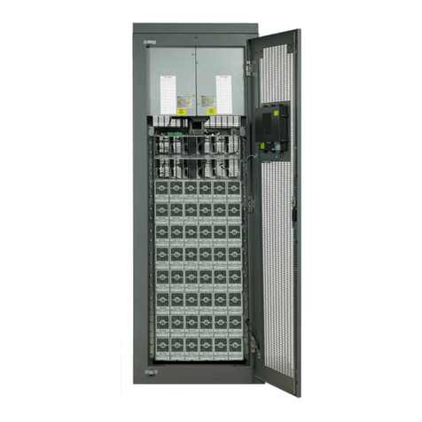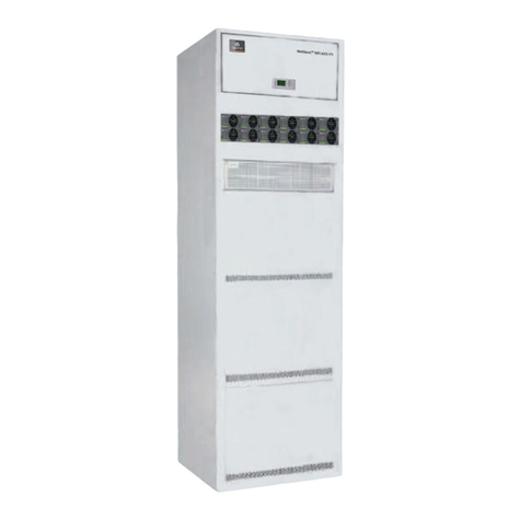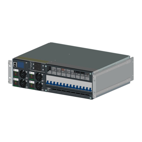
Vertiv™ NetSure™ 7100 Series -48 VDC Power System Installation Manual
Proprietary and Confidential © 2022 Vertiv Group Corp.
TABLE OF CONTENTS
Admonishments Used in this Document..............................................................................................................................v
Important Safety Instructions.................................................................................................................................................vi
Safety Admonishments Definitions .........................................................................................................................................................................................................................vi
Safety and Regulatory Statements..........................................................................................................................................................................................................................vi
Déclarations de Sécurité et de Réglementation..........................................................................................................................................................................................vi
1Customer Documentation Package..................................................................................................................................1
2Installation Acceptance Checklist ....................................................................................................................................1
3Installing the System ............................................................................................................................................................2
3.1 General Requirements..............................................................................................................................................................................................................................................2
3.2 Securing the Relay Rack to the Floor.........................................................................................................................................................................................................3
3.3 Installing Battery Trays............................................................................................................................................................................................................................................4
3.4 Installing Optional Lug Adapter Busbar Kits, Part Nos. 534449 and 514714....................................................................................................... 11
3.5 Installing Circuit Breakers and Fuses.......................................................................................................................................................................................................13
4Setting Jumpers and Switch Options........................................................................................................................... 17
4.1 Circuit Card Locations............................................................................................................................................................................................................................................17
4.2 Jumper on System Interface Board .......................................................................................................................................................................................................... 18
4.3 Switch Setting on IB2 Controller Interface Board ........................................................................................................................................................................19
4.4 Switch Setting on Optional EIB Controller Extended Interface Board .....................................................................................................................19
5Making Electrical Connections .......................................................................................................................................21
5.1 Important Safety Instructions..........................................................................................................................................................................................................................21
5.2 Wiring Considerations.............................................................................................................................................................................................................................................21
5.3 Relay Rack Grounding Connection (Frame Ground) ...............................................................................................................................................................22
5.4 Central Office Ground Connection............................................................................................................................................................................................................22
5.5 SPD (Surge Protection Device) (if equipped) Earth Ground Connection............................................................................................................23
5.6 Nominal 208 VAC / 240 VAC Input and Equipment Grounding Connections................................................................................................ 24
5.7 External Alarm, Reference, Monitoring, and Control Connections ..............................................................................................................................27
5.7.1 Circuit Card Locations....................................................................................................................................................................................................................27
5.7.2 Temperature Probes ........................................................................................................................................................................................................................27
5.7.3 System Interface Board .................................................................................................................................................................................................................28
5.7.4 IB2 (Controller Interface Board) Connections (if required) .........................................................................................................................29
5.7.5 Optional EIB (Controller Extended Interface Board) Connections (if required)......................................................................34
5.8 Connecting a Device or System to the NCU CAN Bus (if required) .........................................................................................................................40
5.9 NCU Controller Ethernet Connection (if required) ....................................................................................................................................................................41
5.10 Load Connections .................................................................................................................................................................................................................................................... 42
5.10.1 Recommended Torques ..............................................................................................................................................................................................................42
5.10.2 Load Connections to Single Voltage Distribution Panels.............................................................................................................................42
5.10.3 Load Connections to Dual Voltage Distribution Panels................................................................................................................................. 42
5.10.4 Load Connections to GMT Distribution Fuse Block..........................................................................................................................................44
5.11 External Battery Connections ....................................................................................................................................................................................................................... 45
5.11.1 Important Safety Instructions .................................................................................................................................................................................................45
5.11.2 Recommended Torques ..............................................................................................................................................................................................................45
5.11.3 Battery Connections to Distribution Cabinet Battery Busbars................................................................................................................45
