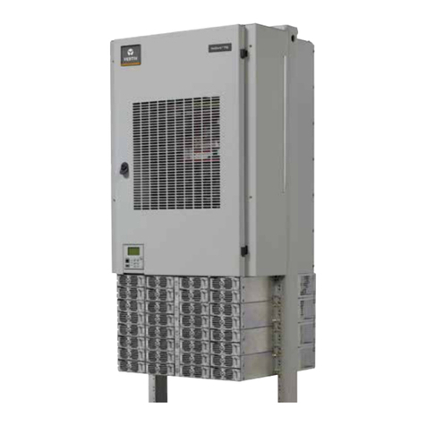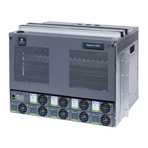
Vertiv |NetSure -48V DC Bulk Output Power System Installation and User Instructions (UM582127100)|Rev. E
TABLE OF CONTENTS
Admonishments Used in this Document............................................................5
Important Safety Instructions ..............................................................................6
General Safety .......................................................................................................................................................... 6
Voltages.......................................................................................................................................................................... 6
AC Input Voltages........................................................................................................................................................6
DC Output and Battery Voltages ..................................................................................................................6
Battery ...............................................................................................................................................................................7
Personal Protective Equipment (PPE)............................................................................................. 8
Hazardous Voltage.............................................................................................................................................. 8
Handling Equipment Containing Static Sensitive Components............................. 8
Maintenance and Replacement Procedures.............................................................................. 8
Static Warning...........................................................................................................9
System Overview.....................................................................................................11
Customer Documentation Package...................................................................................................11
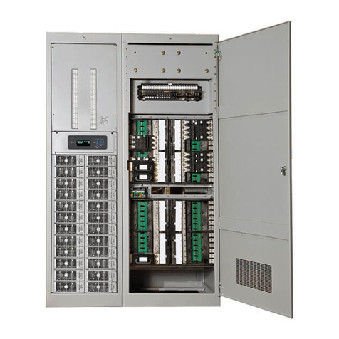
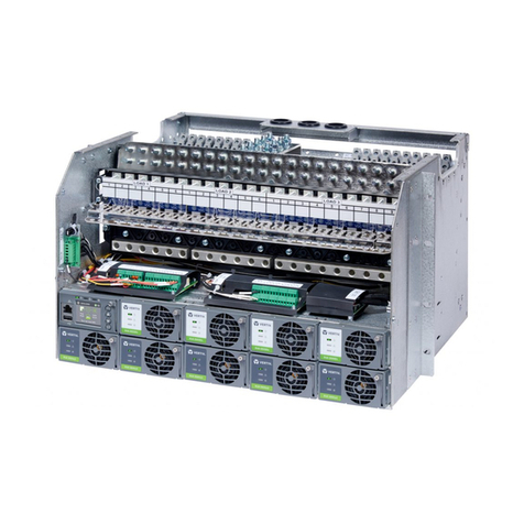
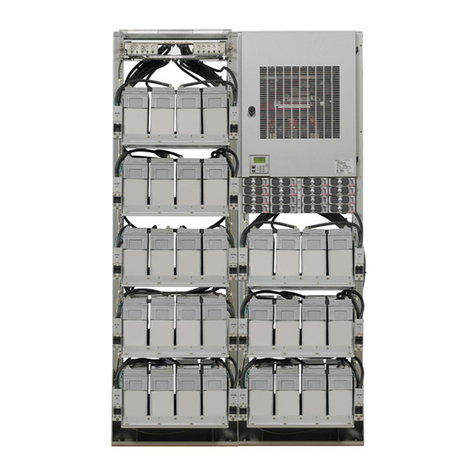
System Description ............................................................................................................................................11
Installation Acceptance Checklist..................................................................... 12
Installing the System............................................................................................. 13
General Requirements....................................................................................................................................13
Securing the Relay Rack to the Floor..............................................................................................14
Mounting System Components in a Relay Rack..................................................................14
Setting Switch Options........................................................................................ 22
Switch Settings on IB2 Interface Board........................................................................................ 22
Making Electrical Connections...........................................................................23
Important Safety Instructions ................................................................................................................ 23
Wiring Considerations.................................................................................................................................... 23
Relay Rack Grounding Connection (Frame Ground) ..................................................... 23
AC Input and AC Input Equipment Grounding Connections to
Rectifier Module Mounting Shelves.................................................................................................24
Connections to 588705000 List 51 and 61 (Single-Phase, Terminal
Blocks)..................................................................................................................................................................................24
Connections to 588705000 List 52 and 62 (Three-Phase, Terminal
Blocks).................................................................................................................................................................................. 27
Connections to 588705000 List 53 and 63 (Single-Phase, Line Cords).............29
External Alarm, Reference, Monitoring, and Control Connections ...................30
External Alarm, Reference, Monitoring, and Control Connection Points
Locations .......................................................................................................................................................................... 30
System Interface Circuit Cards Connections (if required).................................................31
IB2 Controller Interface Board) Connections (if required) ............................................... 34
Controller CAN Bus..................................................................................................................................................39
Controller Ethernet Connection (if required)........................................................................ 40
-48V DC Output Connections ................................................................................................................41
Installing the Rectifier Modules and Initially Starting the System.......... 44
