manuals.online logo
Brands
  1. Home
  2. •
  3. Brands
  4. •
  5. Vestil
  6. •
  7. Lifting System
  8. •
  9. Vestil A-LIFT-R User manual

Vestil A-LIFT-R User manual

Other manuals for A-LIFT-R

1

This manual suits for next models

9

Other Vestil Lifting System manuals

Vestil FPG Series User manual

Vestil

Vestil FPG Series User manual

Vestil FTTM-2 Instruction Manual

Vestil

Vestil FTTM-2 Instruction Manual

Vestil MRR Series User manual

Vestil

Vestil MRR Series User manual

Vestil JMD-1000 User manual

Vestil

Vestil JMD-1000 User manual

Vestil HT-02-1616A User manual

Vestil

Vestil HT-02-1616A User manual

Vestil RR Series User manual

Vestil

Vestil RR Series User manual

Vestil WTJ-20-3 Series User manual

Vestil

Vestil WTJ-20-3 Series User manual

Vestil LM-HRT User manual

Vestil

Vestil LM-HRT User manual

Vestil CYL-P Series User manual

Vestil

Vestil CYL-P Series User manual

Vestil CYL-D-1-PN User manual

Vestil

Vestil CYL-D-1-PN User manual

Vestil EPC Series User manual

Vestil

Vestil EPC Series User manual

Vestil FMDL Series User manual

Vestil

Vestil FMDL Series User manual

Vestil HLD Series User manual

Vestil

Vestil HLD Series User manual
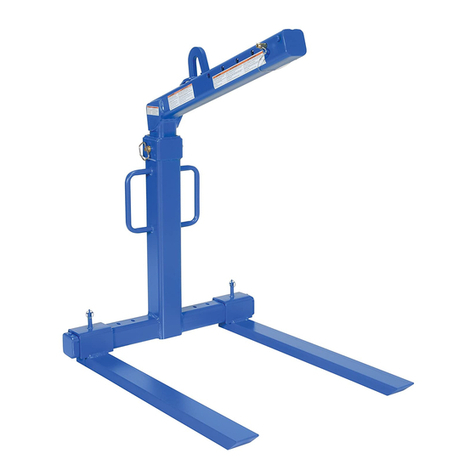
Vestil CART-200-ALUM User manual

Vestil

Vestil CART-200-ALUM User manual

Vestil VDL-22.5 User manual

Vestil

Vestil VDL-22.5 User manual

Vestil OLA-4-42 User manual

Vestil

Vestil OLA-4-42 User manual

Vestil DCT-85 User manual

Vestil

Vestil DCT-85 User manual

Vestil FM-0648 User manual

Vestil

Vestil FM-0648 User manual

Vestil FORK-P User manual

Vestil

Vestil FORK-P User manual

Vestil AIR-1500-D User manual

Vestil

Vestil AIR-1500-D User manual

Vestil EHLTD Series User manual

Vestil

Vestil EHLTD Series User manual

Vestil FMDL-850 User manual

Vestil

Vestil FMDL-850 User manual

Vestil LM-HP-4 User manual

Vestil

Vestil LM-HP-4 User manual

Vestil SLNM Series User manual

Vestil

Vestil SLNM Series User manual

Popular Lifting System manuals by other brands

probst SDH-H-15 operating instructions

probst

probst SDH-H-15 operating instructions

Bruno OUTDOOR ELITE CRE-2110E Operator's manual

Bruno

Bruno OUTDOOR ELITE CRE-2110E Operator's manual

matev FPS Mounting Assembly Installation Guide

matev

matev FPS Mounting Assembly Installation Guide

Butts Tools BXS0002 operating instructions

Butts Tools

Butts Tools BXS0002 operating instructions

Safelift MoveAround MA60 Original instructions

Safelift

Safelift MoveAround MA60 Original instructions

Terex Genie Z452513A-48153 Service and repair manual

Terex

Terex Genie Z452513A-48153 Service and repair manual

Granberg InDIago 510 Operating and care instructions

Granberg

Granberg InDIago 510 Operating and care instructions

EUFAB Bike Lift operating instructions

EUFAB

EUFAB Bike Lift operating instructions

morse 82H-124 Operator's manual

morse

morse 82H-124 Operator's manual

Braun NL955 Series Operator's manual

Braun

Braun NL955 Series Operator's manual

Protekt AT 252 instruction manual

Protekt

Protekt AT 252 instruction manual

R. Beck Maschinenbau HS 600 operating manual

R. Beck Maschinenbau

R. Beck Maschinenbau HS 600 operating manual

Nova Technology International, LLC NAS Series quick start guide

Nova Technology International, LLC

Nova Technology International, LLC NAS Series quick start guide

Genie Z-60/34 Operator's manual

Genie

Genie Z-60/34 Operator's manual

Screen Technics INTERFIT Vertical Up Lift instructions

Screen Technics

Screen Technics INTERFIT Vertical Up Lift instructions

Drive DUPONT SAMERY Hermes user manual

Drive

Drive DUPONT SAMERY Hermes user manual

Custom Equipment Hy-Brid 3 Series MAINTENANCE & TROUBLESHOOTING MANUAL

Custom Equipment

Custom Equipment Hy-Brid 3 Series MAINTENANCE & TROUBLESHOOTING MANUAL

Custom Equipment Hy-Brid Lifts 2 Series Maintenance and troubleshooting manual

Custom Equipment

Custom Equipment Hy-Brid Lifts 2 Series Maintenance and troubleshooting manual

manuals.online logo
manuals.online logoBrands
  • About & Mission
  • Contact us
  • Privacy Policy
  • Terms and Conditions

Copyright 2025 Manuals.Online. All Rights Reserved.

INSTRUCTION MANUAL
FOR HAND WINCH LIFT TRUCKS
MODELS COVERED:
A
-
Lift
-
R
A
-
Lift
-
S
A
-
Lift
-
CB
MODEL NO.________________________
SERIAL NO.________________________
VESTIL MANUFACTURING CORP.
2999 NORTH WAYNE STREET,P.O. BOX 507, ANGOLA,IN 46703
TELEPHONE:(260) 665-7586 -OR-TOLL FREE (800) 348-0868
FAX:(260) 665-1339
URL:WWW.VESTILMFG.COM EMAIL:SALES@VESTIL.COM
Each hand winch lift truck conforms to the generalized specifications disclosed in this manual and
fulfills our demanding standards for quality, safety and durability. This manual adopts relevant
provisions of ANSI/ITSDF standard B56.10-2006, “Safety Standard for Manually Propelled High Lift
Industrial Trucks”.
SAFETY PRINCIPLES
Vestil Manufacturing Corp. recognizes the critical importance of workplace safety. Each person
who might participate in the assembly, use, inspection or maintenance of the product must read the
entire manual and fully understand the directions BEFORE assembling, using, inspecting or
maintaining the A-Lift. If you do not understand an instruction, contact Vestil for clarification. Failure
to read and adhere to all of the directions in this manual prior to assembly, use, inspection or
maintenance is a misuse of the product and could lead to serious personal injury or death.
Vestil is not liable for any injury or property damage that occurs as a consequence of failing to
apply the safe operation and maintenance procedures explained in this manual or that appear on
labels affixed to the product. Similarly, failure to exercise good judgment and common sense may
result in property damage, serious personal injury, or death, and are not the responsibility of Vestil.
This manual applies the hazard identification methods recommended for instruction manuals by
the American National Standards Institute (ANSI) in ANSI standard Z535.6-2006. In accordance with
ANSI guidelines, this manual identifies personal injury risks and situations that could lead to property
damage with SIGNAL WORDS. These signal words announce an associated safety message. The
reader must understand that the signal word chosen to identify a particular hazard conveys
information about the seriousness of that hazard according to the following convention:
Identifies a hazardous situation which, if not
avoided, WILL result in DEATH or SERIOUS INJURY. Use of this
signal word is limited to the most extreme situations.
These symbols
identify hazards
that may result in
personal injury
Identifies a hazardous situation which, if not
avoided, COULD result in DEATH or SERIOUS INJURY.
Indicates a hazardous situation which, if not
avoided, COULD result in MINOR or MODERATE injury. Although
Z535.6-2006 approves the use of “CAUTION” without an
accompanying safety alert symbol (black equilateral triangle with
yellow exclamation point) as an alternative to “NOTICE”, this manual
differentiates between hazards that pose a risk of personal injury and
those that create mere property damage situations. CAUTION
appears exclusively in conjunction with the safety alert symbol
to identify injury risks.
Identifies practices not related to personal injury, such as operation
that could damage the A-Lift. Note: No safety alert symbol (equilateral triangle with
an exclamation point inside) accompanies this signal word.
- 2 -
- 3 -
TABLE OF CONTENTS
SafetyPrinciples 2
ProductIntroduction 4
SafetyGuidelines 5
Assembly and Operation Instructions 7-11
Maintenance & Inspections 12
TABLE OF FIGURES
FIG. 1A: HP &EHP Telescoping Mast 5
FIG. 1B: Diagram of Assembled A-Lift 6
FIG. 2: Label Placement Diagram 13
PRODUCT INTRODUCTION
Thank you for purchasing a Hand Winch Lift Truck (“winch lift,”
“A-Lift,” or simply “lifter”) made by Vestil Manufacturing Corporation
(“Vestil”). Our winch lifts are durable, high-quality products that
combine safety features and rigorous engineering. Although the
winch lift’s operation is relatively intuitive, all personnel must
familiarize themselves with the instructions provided in this manual.
Each A-lift is constructed from steel and aluminum parts, a combination of
materials that provides strength and reduces weight. The lift improves efficiency and
prevents injuries that could occur while lifting and moving materials. Use your A-Lift to
move materials like boxes and office equipment.
The design includes lifting mechanisms actuated by a manual winch with a foldable
handle. One complete, clockwise revolution of the handle raises the forks by 1 inch.
Additionally, a pivoting carriage latch can be used to secure the fork carriage in a safe
position for transport. Further product specifications appear in the following table:
Overall Size in Inches Maximum Rated Net Weight
Model (W x L x H) Load in Pounds in Pounds
A-Lift-R 24 x 35 x 68 500 (~227kg) 136 (~62kg)
A-Lift-R-HP 24 x 35 x 68 400 (~182kg) 140 (~64kg)
A-Lift-S 29 x 43 x 68 500 (~227kg) 140 (~64kg)
A-Lift-S-HP 29 x 43 x 68 400 (~182kg) 145 (~66kg)
A-Lift-S-EHP 29 x 43 x 79 350 (~159kg) 154 (~70kg)
A-Lift-CB 29 x 47 x 68 500 (~227kg) 396 (~180kg)
A-Lift-CB-HP 29 x 47 x 68 400 (~182kg) 418 (~190kg)
A-Lift-CB-EHP 29 x 47 x 79 350 (~159kg) 449 (~204kg)
A-Lift-DK (Deck Platform) 20-1/2 x 24-1/4 25 (~11kg)
A-Lift-PN: 10in. pneumatic rear wheels 20 (~9kg)
Vestil Manufacturing Corp. created this manual to acquaint owners and users of
our winch lifts with safe use and maintenance procedures. However, employers are
responsible for instructing employees to use the product properly. Employees and any
other persons, who might foreseeably use, install, or perform maintenance on the
A-Lift, must read and understand every instruction before using it. Furthermore,
persons who use the Lifter should have access to the manual at all times, and should
consult the directions before each use. Contact Vestil for answers to any question you
have after reading the entire manual.
Although we strive to identify the foreseeable hazardous situations that could arise,
this manual cannot address every conceivable danger. The end-user is ultimately
responsible for exercising sound judgment at all times.
- 4 -
SAFETY GUIDELINES
Read the entire manual before you use the Winch Lift for the first time and before each subsequent use.
Refer to the manual for safe use and maintenance procedures described on p. 7-13. If questions remain
after you finish reading the manual, contact Vestil for answers. DO NOT attempt to resolve any problems
with the Lift unless you are certain that it will be safe to use afterwards. NEVER modify the product in any
way without the express, written approval of Vestil.
•Electrocution Risk: DO NOT contact electrical wires with the winch lift or load! Be aware of all
overhead obstacles and take precautions to avoid contact with them.
•ALWAYS inspect the Lifter before each use according to the inspection instructions on p. 12. DO NOT use
the Lifter unless it passes the inspection.
•Prior to each use, ALWAYS inspect the area where you intend to use the lifter. Inspect the area for unusual
conditions that might require special precautions. See “Notice” on p. 10.
•DO NOT use a malfunctioning lifter. Always perform the “Function Test” described in the Notice on p. 10
before each use.
•Regardless of whether the lifter is loaded or unloaded, DO NOT stand or travel under the forks and DO NOT
allow any other person to stand or travel under the forks.
•Inform all persons in the area that you are going to use the Lifter, and instruct them to stay clear of the device
and the supported load during operation.
•ALWAYS make sure that your clothing and body do not contact the mast structure, lifting mechanisms, or
carriage during operation. ONLY operate the lifter from the “Operator’s Position,” shown on p. 10. DO NOT
move the lifter or raise or lower the forks unless you are in the operator’s position.
•DO NOT allow people to ride the lifter.
•ALWAYS load the A-lift according to the list of recommendations that appears below. Failure to properly
position a load on the forks (or platform) might cause the lifter to tip over and you could be injured as a
consequence.
1. DO NOT exceed the A-Lift’s maximum rated load. The rated load (capacity) of your Lifter is posted on
a product label as shown in Fig. 2 on p. 13.
2. ONLY move loads using the forks or the optional deck platform (“load-engaging means”).
3. DO NOT handle off-center loads or loads that cannot be centered. ALWAYS properly center the load.
4. Start and stop gradually to avoid upsetting the load from the forks/platform.
5. NEVER tilt the lifter while carrying a load. All four castors must maintain contact with the ground when
a load is on the forks/platform.
FIG. 1A: HP & EHP models have telescoping mast frame
7
6
- 5 -
- 6 -
FIG. 1B: Diagram of Assembled A-Lift
5
3
4
2
11
10
8
12
26
1
7
14
21
22
25
9 or 23
28
R Models
27
27
2
14*
S Models
13
15
9 or 23 16
14
20
15 17
19
18
CB Models
“Standard Units” refers to A-Lift-R, -S, & -CB models; “HP Units” means A-Lift-R-HP, -S-HP, and -CB-HP models; “EHP
Units” indicates A-Lift-S-EHP and –CB-EHP models.
Diagram
Number
Description Part
Number
Quantity Diagram
Number
Description Part
Number
Quantity
1 Operator Handle A-Lift-1 1 15 Leg Lock Pin A-Lift-CB-15 2
2 Loading Wheels A-Lift-2 2 16 2 inch Castor A-Lift-S-16 2
3 Upper Pulley A-Lift-3 1 17 4 inch Fixed Wheel A-Lift-CB-17 2
4 Cable Anchor Bolt A-Lift-4 1 18 Adjustable Leg A-Lift-CB-18 2
5
Cable (Standard Units)
Cable (HP Units)
Cable (EHP Units)
A-Lift-5
A-Lift-HP-5
A-Lift-EHP-5
1 19 5 inch Swivel Castor A-Lift-CB-19 2
6 Telescoping Mast Frame
(only HP & EHP Units) A-Lift-6 1 20 Counterweight Support
Weldment A-Lift-CB-20 1
7 Mast Frame A-Lift-7 1 21 Castor A-Lift-R-21 2
8 Decal Plate A-Lift-8 1 22 Standard Support Legs A-Lift-R-22 2
9 Pneumatic Wheel A-Lift-S-9 2 23 Solid Rear Wheel A-Lift-23 2
10 Carriage A-Lift-10 1 24 Brake A-Lift-24 1
11 Carriage crossbars A-Lift-11 2 25 Fork Lock Pin A-Lift-25 4
12 Fork A-Lift-12 2 26 Winch Mounting Bracket A-Lift-26 1
13 Adjustable Leg S A-Lift-S-13 2 27 Winch A-Lift-27 1
14
14* Lower Pulley A-Lift-14
A-Lift-S-14 1 28 Deck Platform A-Lift-Deck 1
Assembly Instructions
Vestil ships winch lifts to its customers in a mostly assembled form. The minimal assembly that is required differs by
model, so follow the directions that correspond to your lifter.
If you purchased an A-Lift-R or A-Lift-S, you will receive 3 pieces:
- 7 -
Support leg
openings
1). Main Assembly
3). Box 2 contains:
forks (2).
2). Box 1 contains: standard support legs (2),
fork retaining pins (4), winch handle (1).
Step 1: Connect the support legs to the main assembly by following instructions (a) through (e).
(a) Insert a support leg into each of the
openings in the main assembly.
(b) One at a time, pull the retaining pegs
to allow the legs to slide further into
the openings.
(c) Slowly release the pegs. You may
have to wiggle the leg to get the peg
to drop.
(d) Pull upwards on each of the support
legs to verify that they are held in
place by the pegs. The legs should
not be able to slide out of the opening
(e) If a leg comes out of the opening, the
corresponding peg did not engage
p
ro
p
erl
y
. Re
p
eat
(
a
)
thou
g
h
(
d
)
.
Spring-loaded retaining peg
Step 2: Lift the assembly to the upright position (photo a), lock the brakes (photo b) and fasten the winch handle to the
winch body (photos c – f).
Engage the brakes by
pressing down on the
brake actuator Remove the handle
retaining bolt and washer
(circled)
c
b
a
Handle connector
Winch body with bolt and
washer removed
d
- 8 -
e
Step 3: Attach the forks to the carriage.
Step 4: Turn the winch handle counterclockwise to lower the forks. Lower the forks until they are a few inches above
the support legs (22), and then push the lifter to the desired location.
Counterbalanced lifters (A-Lift-CB):
Step 1: Attach the 5 inch swivel castors (19) to the counterweight support weldment (20).
f
Set the handle latch pin (circled) to lock
the handle, and then fasten the handle to
the handle connector with the bolt and
washer that you removed in step (c).
Note: It may be necessary to secure
the washer against the bolt head with
a nut BEFORE you fasten the bolt to
the connector. This technique will
prevent the bolt from loosening when
the handle is rotated counterclockwise
to lower the forks.
c
b
d
Instructions as shown in the
photographs to the right:
b.
A
lign the holes in the
forks with the carriage cross-
bars (11); then push the
forks until they contact the
carriage. Note: It may be
necessary to tap the forks
into place with a rubber
mallet.
c. Slide fork retaining pins
(25) through the holes in
each of the carriage
crossbars.
d. Lock the pins into place
by swinging the ring portion
of each pin downward
Nylock nut
Bolt
Slide the handle onto the
handle connecto
r
Grasp the
operator handle
(1) with one
hand; turn the
winch handle
clockwise with
the other hand.
Raise the
carriage (10) to a
comfortable work
height.
a
Drop bolts through
each of the holes.
Secure each bolt with a
nylock nut. Tighten all
of the connections with
a pair of wrenches.
Turn the weldment over so that
the underside faces upwards.
Align the castors with the bolt
holes in the weldment.
a
b
Step 2: Attach the weldment to the main assembly.
Step 3: Install and position the forks by following R & S model fork installation steps 3 & 4 on p. 8.
Operation Instructions:
- 9 -
The operating instructions in this manual are meant to supplement the operation recommendations of ITSDF
standard B56.10-2006. According to the standard, the A-Lift is a, “Manually propelled high lift industrial truck”. Safe
operation of this type of device is the operator’s responsibility.
DO NOT operate the winch lift until you read AND understand all of the instructions. If you do not
understand an instruction, contact Vestil for clarification.
•Review ALL of the safety guidelines on p. 5 before each use;
•ALWAYS use proper lifting techniques;
•Enlist a coworker to help you lift, load, and unload the A-lift;
•DO NOT use the lifter on stairs.
g. Fasten the bolts in
place using a flat washer,
followed by a lock washer
and then a nut.
f. Set the four counterweights on the weldment; then insert the
counterweight retaining bolts beginning with the outermost weight.
e. Bolt the
weldment to
the main
assembly, and
then secure
the bolts with
nuts.
d. Align the
bolt holes in
the weldment
with the holes
present in the
weldment
brackets
(circled in
p
hotos c & d
)
.
c. Lay the
main
assembly
- winch
side up -
on the
ground.
b. Lock both of the castors
a
An “Operator” is a person who is trained and authorized to control a manually propelled high lift industrial
truck. ONLY persons who have successfully completed the suggested training program outlined in B56.10-2006, at
4.17 on p. 4, and 4.18.1-.4 on p. 4-5 should operate the A-Lift. Operators must:
•Develop safe working habits and an awareness of hazardous conditions occurring or present during operation of
the lifter;
•Inspect the area where the lifter will be used before each use to identify unusual operating conditions.
Implement additional safety precautions as conditions require. Such conditions might include:
1. Irregularities in the floor/surface;
2. Debris or other obstructions on the floor/surface;
3. Unsound surfaces or surfaces that cannot support the weight of yourself, the lifter and the load either
together or separately;
•Perform the following function test before each use:
1. Test the winch: raise and lower the forks;
2. Test the brakes: press down on the brake actuator to engage the brakes; then attempt to push the lift forward.
3. Test the castors: push the lifter to test the castors.
The end-user bears responsibility for verifying that the lifter complies with all regulations, codes, and standards
that apply in the location where it is used.
Inspect the lifter as recommended in the “Maintenance and Inspection” section of this manual (p. 12-13). Use the
lifter ONLY IF the lifter passes the inspection and is deemed safe to use by designated inspection personnel.
Step 1 (for S and CB Models): Adjust the legs to provide the desired wheel base. Set the brake (S models) or lock the
castors (CB models). Remove the forks and lock the carriage using the pivoting carriage latch (photo a). Slowly tilt
the lifter backwards until the loading wheels contact the ground. Pull the leg adjustment peg (photo b) and slide the
leg in the desired direction. Reset the peg in the first or second adjustment setting (photo c) as the job requires.
2
- 10 -
Step 2: Always maneuver the A-lift from the “Operator’s Position” using the Normal Maneuvering Stance shown
below.
Step 3: Move the lifter to a position near the intended load and lock both of the locking castors.
Raise the
forks to a
comfortable
height.
a
1
b
c
b. Walk behind the lifter and keep your
feet clear of the castors.
DO NOT place one
foot on the counterweights and propel
the lifter with the other foot. Doing so
will make the lifter more difficult to
control.
a. Grasp the
operator handle at
each end. This
will provide the
greatest degree of
steering control.
a
b
Lower the
forks until the
load is a few
inches above
the adjustable
leg (shown by
arrow in
photo above).
Set the
load on the
forks. The
load must
rest against
the back of
the forks.